Subscribe to the newsletter
Continuity testing is a test of a telephone cable for the integrity of the cores. The need for such a procedure may arise at any second. Your phone may stop working for a variety of reasons. For example, as a result of excavation work on the site, moving furniture in the house or after a thunderstorm. Also, the need for ringing may arise when carrying out electrical installation work - for example, when marking wires and cores, checking insulation. In any of these cases, it is important to know how to ring a telephone cable.
How to check the cable for a break?
You can ring a telephone cable in several ways - for example, using a special transformer, ohmmeter, megaohmmeter, etc. However, a telephone handset is best suited for these purposes. Such a device cannot be called either a tool or a device. At the same time, telephone operators most often use just such a handset. It is easy to use and mobile. This special handset can be bought in a store or made independently based on a handset from an old dial or push-button device. But how can you check a telephone cable for a break using such a handset?
Measuring the capacitance of a telephone cable should be carried out in the following order:
• Invite an assistant. • Identify the common core. This is any colored vein, for example green. This is where you need to start calling. All other veins will be called relative to this vein. • Connect one terminal of the main tube to this green conductor, and the other to any other desired conductor. • Connect one clamp of the auxiliary tube to the green wire (on the other side of the cable). Using the second clamp, switch through all the wires in turn. Find the core to which your assistant is connected. • When you connect the clamp of the auxiliary tube to the desired core, you will hear crackling and clicking sounds. This suggests that a closed circuit has arisen between the desired and green vein. • Through the tube, discuss with your assistant how you will mark the found vein. It is necessary to put tags with markings on both sides of the wire. Prepare them in advance. • Next, repeat everything described above, as many times as there are wires in the cable. • If a break is not detected, then crimp the entire cores using NShVI sleeve lugs and insert them into the terminal block.
What to do if there are no colored veins?
How to check a telephone cable for a break if there are no colored wires?
Here you can start measurements from any core. You need to do the following: • Connect one clamp of the main tube to the desired core. • Connect the second clamp to ground. If the cable is armored, then its armor can be used instead of ground.
All. Now you know how to ring a telephone cable. By making a call, you will be able to talk to your partner at a distance. You can, for example, specify the color of the cores. The cable can be located between different rooms or buildings. You don't have to walk from one place to another, which is certainly convenient.
Knowing how to check a telephone cable, you can quickly determine the reason for the lack of dial tone in the handset. This will allow you to take the right actions in a timely manner and establish communication.
is one of the leaders in the sale of cable products and has warehouses located in almost all regions of the Russian Federation. After consulting with the company’s specialists, you can purchase the brand of telephone cable you need at competitive prices.
Modern civilization provides a wide variety of benefits that make our lives easier. These include mobile phones and wireless communications. They help us hear the voices of family and friends, friends and acquaintances over long distances, without using wires in this case. However, today regular landline phones still remain relevant. Although they are large and require connection via special wires, these devices can be useful at home when your mobile phone is discharged or if you want to chat without spending a small amount of money on the conversation (tariffs are usually lower in this case). If you decide to connect such a telephone or are simply interested in this topic, then you should find out more information on how to check the voltage in the telephone line.
How to ring wires: methods and devices used
Testing wires at home can be done in two ways: using a multimeter and using improvised means such as an ordinary light bulb with a socket. The last option is somewhat inconvenient, but the first is quite simple and accessible for independent implementation. We will consider both options, since sometimes it happens that there is no device at hand, but the result is needed immediately.
Let's start with the first method, which involves using a multimeter. To make it clearer, let’s look at a simple example and use a wire tester to check the integrity of the wire to connect the computer system unit to the apartment electrical wiring. As a rule, it contains three cores - we will work with them.
How to connect wires photo
We take out a multimeter, turn it on in resistance measurement mode (ohmmeter), close the contact probes and set the indicator arrow to zero. Now let's start testing the cable. We attach one probe to one of the contacts of the plug, and insert the second one in turn into the holes of the connector to connect the cable to the system unit. We observe the indicators of the device, or rather its needle - if the ohmmeter shows the wire resistance within 2-3 Ohms, then the core is in good working order, but if it exceeds 10 Ohms, this is a clear sign that there is a break on this core. It may happen that the multimeter needle does not react at all to your actions - this only means that the contact on the plug and on the connector do not belong to the same core of the electrical wire.
How to test wires with a tester
This is the way to test the wires with a multimeter. I would like to note that this testing method is suitable for wires for any purpose - telephone, computer, electrical.
In almost exactly the same way, you can carry out dialing using a tester equipped with a voltage indicator. It should be understood that no voltage is supplied through a broken wire, and in order to ring the wires with a tester, it is enough to measure the voltage on its wires. On the indicator it should be displayed as identical digital values, which have a different sign (“+” or “-”). The only drawback of this testing method is that the tester is able to determine the parameters of the wire only when it is energized.
Wire continuity photo
Another testing method is suitable for testing exclusively electrical wiring cables - it involves using a piece of ordinary wire with a light bulb. If we are talking about continuity of the lighting circuit, then you can get by with a long piece of single-core wire. The essence of this method is as follows. In the distribution box, the wires leading to one or another consumer of electrical energy are one by one discarded from the general power circuit and instead of them, a separate wire is connected directly to the consumer, the operability of which is beyond doubt. If everything works, then it is the disconnected wire that can be considered faulty. If not, then we restore it to its place and repeat the operation with another wire of the electrical circuit.
In principle, by changing the starting point of connecting the additional wire and using a lamp as an indicator, you can ring almost any section of the apartment wiring. The method is excellent, and most importantly effective - its only drawback is some inconvenience associated with constant switching of wires.
How to test wires with a multimeter photo
Types of telephone communication lines. Principle of operation
Telephone communication lines are divided into two types: analog and digital. The first has existed since ancient times and is actively used today. It is relatively simple in functionality and also has stable settings (for example, voice pitch or volume). When we speak into a handset, the microphone converts our sounds into an analog signal, which is sent at lightning speed through the wires to the central telephone exchange. She digitizes the received data. The result is everything that we said, but only in a processed and improved version.
Thanks to such actions, the station clears the voice of interference and other noise, making it better. Then the signal again becomes analog and is transmitted to the device through which another person is listening to us. That is, we see that the first type of signal is used more often, and it is precisely this type that is used in landline telephones of our houses and apartments. So it's time to talk about voltage on an analog telephone line. We will learn about everything you need: from basic knowledge to incredible things related to our topic.
What is the voltage on the telephone line?
It is no different from that which is found in ordinary electrical wires. More precisely, it differs only in its size. The voltage in sockets, chandeliers, household appliances, switches and other devices is 220V. In a telephone line it is much smaller, since very little is required from it. She does not need to power huge electric boilers or lighting fixtures. All that is required is the transmission of the sound of the voice at certain distances.
Therefore, you need to quickly answer the main question: “What voltage should be in the telephone line?” As a rule, it is 40-60V (if the handset is on the phone). When a call is made to your landline device, the voltage begins to change. Fluctuations can even reach 120V. The voltage in the telephone line, on the contrary, begins to drop sharply when the handset is lifted. In this case, it is equal to 6-12V, which is quite small in magnitude. However, if the handset wire is damaged and you accidentally touch it, you can get quite unpleasant sensations.
Determine the telephone line voltage yourself
Perhaps someday you will decide to install a landline telephone in your home. It is likely that you already have it, but for some unknown reason it has stopped working or is performing its tasks very poorly. In the first case (to select a suitable device) and the last (to carry out repairs correctly), it is necessary to measure the voltage in the telephone line. This can be done using a special device called a voltmeter. It is connected in parallel and indicates the voltage in the form of numbers or using an arrow. Please note that this device is capable of displaying the voltage value of direct current (indicated by the “-“ sign) and alternating current (indicated by the “ sign
"). You will need to find out the value of the DC voltage.
Finding out meaning in unusual ways
If you do not have a voltmeter (which is quite possible, since this is not an essential item), then especially for this case, people experienced in this matter have come up with other methods for checking the voltage in the telephone line. The method is quite funny (at least it seems so at first glance), but very practical, easy and convenient. To implement it you will need a well-known vegetable - potatoes. Yes, yes, exactly potatoes.
The root vegetable needs to be cut in half, then insert (preferably into the core of the vegetable) the two ends of the stripped wire to a depth of one to two centimeters. The distance between two bare conductors should be very small. The main thing is that they do not touch, otherwise the network will short out. And the following changes should occur with potatoes. Around the conductor, which is connected to the positive field, the flesh of the vegetable will turn a little green, and foam will form near the negative one. In addition, the wire itself with the minus sign will become dark. This can be seen when you remove it from the vegetable.
What is a cable continuity test kit?
With the passage of time and the development of technology, specialized devices for testing cable pairs - test kits - appeared. The tone generator included in them is capable of not only supplying power to the microphones of the test tubes for organizing voice communication, but also sending a tone signal to the pair for easy identification at the return end. As the signal propagates along the conductor, it creates an electromagnetic field around it, which is detected by the receiver at the remote end.
Rice. 2 Organization of an official communication channel between installers using the Greenlee 77HP generator
As a receiver, you can use a test handset (headset), one of the terminals of which should be connected to the cable screen, the other should be used as a probe. However, it is more practical for this purpose to use a special inductive probe, which is also an integral part of the test kit.
Fig.3 Identification of a pair at the opposite end of the cable using the Greenlee 200EP-G inductive probe
A loud signal from the generator will be perfectly audible in the speaker of the probe even without direct contact of its tip with the desired pair, however, as you approach it, the signal level will be higher, which makes it easy to cope with the task. Some inductive probes have connectors for connecting a telephone headset and even a test handset.
Connecting a new phone
As mentioned above, the voltage in the telephone line is usually checked when a new device should be installed or an existing one should be repaired. Let's talk about connection first. But before starting this process, you need to consider the main types of telephone sockets. The first and most common type is RTShK-4. The connection is established in this way: the contacts of the socket (the line wires are connected to them) must coincide with the contacts of the plug (the telephone wires are connected to them).
The 623K RJ-116P4C socket is a more modern option, but also outdated. It is used not only to establish telephone communications, but also to provide Internet access. The two line conductors should generally be connected to the green and red wires.
You can connect your phone without a socket, using an RJ-11 plug. To do this, you need to take a telephone line wire, strip its two contacts and insert them into the RJ-11 connector. The wire is clamped using special pliers (crimpers) or manually (for example, by tapping the lamellas with the end of a flat screwdriver to the required depth).
Errors in wire continuity
Often inexperienced craftsmen make various mistakes, let’s look at the main ones:
- measurement modes are set incorrectly
- In the process of testing wires using a step-down transformer or a pointer tester, you need to check the power source. The voltage level should be between 3.5 and 4.5 volts. If this is not checked, the voltage will be measured with a large error
- Before testing, you need to carefully clean the contacts on the cable wires and measuring probes. In this case, there is no need to clean the gold-plated contacts; just wipe them with cotton wool and technical alcohol
- when using pointer instruments, it is important not to confuse the scale, but should be for alternating voltage with the sign “V~”
- To test the wires in the wiring harnesses of the distribution cabinet, the contacts on both sides must be disconnected from all components of the equipment.
Telephone or telephone line repair
Let's consider the second case, when voltage measurement is used on a telephone line. We said that repairs apply to this situation. A situation may occur in which the phone stops working for some reason. Then you should call a specialist: he will examine the device, find the cause of the malfunction, and quickly and efficiently fix everything. You can do the repair yourself. This is where methods for measuring telephone network voltage help. With their help, it is easy to determine what exactly has gone wrong. Perhaps the phone itself is broken. In this case the voltage will be fine. If it is missing, then most likely there is a breakdown on the communication line. Then you need to check the wire that goes to the outlet or the phone itself for damage. If a malfunction is detected, the wire should be replaced completely or directly at the point of failure.
Why else do you need to know the voltage of the telephone line?
Agree that you live in an apartment or house, stuffed with modern means, devices and other gadgets. All of them are somehow connected to wires, since they cannot work without electricity.
It’s probably still useful to know what voltage a particular conductor has, since we use these devices almost every day. Therefore, if you know the voltage of the current passing in all the wires, then it is obvious that you can avoid danger. After all, a large electric discharge can give a person a lot of unpleasant sensations in the event of damage to its carrier and contact with it. But in other situations, knowledge in this area and firm confidence in the inability of the wire for various reasons to give an electric shock will help maintain calm and good mood.
In conclusion
Thus, knowing the voltage in the telephone communication line, you can easily and simply install a new device, repair an old one, and avoid contact with exposed conductors. It will also broaden your horizons and erudition, and you will have the opportunity to show off your unusual knowledge to your friends.
When carrying out electrical installation work, it may be necessary to test the cable, for example, when marking cores and wires, checking the insulation and integrity of the wiring, as well as searching for a broken electrical cable. Let's consider the ways in which testing can be carried out, as well as the equipment necessary for this purpose.
Process description
Cable or wire testing is the process of checking the integrity of an electrical conductor. During this process, the absence of cable/wire breaks and short circuits is checked.
Carrying out the appropriate procedure allows you to determine the location of the breakdown in the network.
Network performance should be measured correctly
Methods
Testing methods depend on the purpose for which it is performed. To check the integrity of the cable for a break or electrical connection between its wires (short circuit), the continuity test can be done with a tester based on a battery and a light bulb, or you can use a multimeter for this purpose. The latter is preferable.
Despite the fact that the price of a multimeter is higher than a primitive device, we recommend buying it; this device will always be useful in the household.
The simplest device for testing an electrical cable
To check the cable, the multimeter must be turned on in the appropriate mode (diode or buzzer image).
Multimeter set to dialing mode
The testing methodology is as follows:
When checking a wire for a break, the tester is connected to its ends as shown in the figure. If the cable is intact, the light will glow (when testing with a multimeter, a characteristic sound signal will be heard).
Checking for a break
Explanations for the picture:
- A – electrical cable;
- B – cable cores;
- C – power source (battery);
- D – light bulb.
If the cable has already been laid, then on one side it is necessary to connect the wires together and ring the wires at the other end;
Second option for checking the power cable
when checking the presence of an electrical connection between the cable cores, the tester probes are connected to different wires. Unlike the previous example, there is no need to twist the wires on the other side. If there is no short circuit between the wires, the light will not light (when testing with a multimeter, no beep will sound).
Setting up and preparing the multimeter
To use the multimeter correctly, you need to configure it. This means that you need to select the value to be measured and the limit of its operation, that is, the value beyond which it will not go.
Symbols on the front panel of the meter
A multimeter can be used to check various electrical quantities: current, voltage, resistance, frequency. It is also used to test the performance of various radio elements: resistors, capacitors, diodes and transistors. The very part of the word “multiple” implies the presence of several types of measurements. To select these types, there is a knob on the front panel of the tester, by turning which you can select the required value.
There is a higher class type of multimeter, for example, Agilent, in which the selection of measurement values is made not with a rotary knob, but with buttons. To select a value, simply click on the button corresponding to this value.
In most cases, the symbols depicted on the body of the multimeter represent designations of electrical quantities accepted in physics or conventional graphic designations of radioelements intended for testing . On the front panel you can find the following symbols:
- U - voltage symbol;
- V - stands for volts, this is also a measure of voltage;
- I is the current; when you set the knob to this designation, the current strength will be measured;
- A - amperes, a measure of current strength;
- Ω, R - symbol of resistance;
- Ohm is a measure of resistance, Ohms;
- -| |- - this icon indicates a capacitor, the multimeter will measure its capacitance;
- Diodes and transistors are also marked on the tester body with their symbols.
Read also: Beautiful metal porch railings photo
But not only the measured values are indicated on the front panel of the tester: the holes for connecting the probes also have their own designations. One of the meter slots will always be occupied by the black probe. This is a common hole, it is usually marked with the inscription COM, which means “common”. In addition to it, the multimeter has two or three working holes, designed respectively for measuring voltage, low current and high current.
The socket marked U, Ω, Hz is intended for measuring resistance, voltage and frequency, as well as for testing various radio elements. You also need to install a probe here to test wires and cables for breaks.
The hole marked mA (mA) is used to test low currents (up to 1 ampere), and the hole marked A (10 A) is needed to measure high amperages.
Also next to the voltage and current icons there are symbols
or -. This indicates the nature of the measured quantity: direct or alternating current or voltage.
Limits of measured values
In addition to designations of the values of the parameters being tested, designations of measurement limits are printed on the front panel of the multimeter. In more advanced equipment, these inscriptions are not present, since the tester electronics itself selects the limit based on the signal supplied to it at the input. However, most multimeters require manual adjustment of measurement limits.
Typically, limits are given by numbers that are multiples of 2: 2, 20, 200... Thus, when choosing a limit, you should be guided by the rule: choose a limit higher than the one being measured, but of the same order. For example, to measure the voltage in a home electrical network (in an outlet), you need to select the AC voltage measurement mode and the measurement limit of 2000 volts. And to test the wires with a multimeter, you need to select the resistance mode and the minimum measurement limit of 2 ohms. However, long cables require a higher measurement limit of 20 ohms. Additionally, you can turn on the button with a sound signal that sounds when a short circuit occurs (circuit presence).
Connecting the tester
To check the parameters of electrical circuits and the continuity of wires and cables with a multimeter, you must correctly connect the meter to the circuit being tested. When checking for circuit integrity, the required area between the meter leads is checked. Therefore, the tester is connected to the terminals of the circuit. If voltage is being measured, the multimeter must be connected in parallel to the section where the voltage is being tested.
When measuring current, the multimeter must be connected in series to the open circuit of the circuit being tested, for example, between the power supply terminal and the load terminal.
Testing multi-core cables for the purpose of marking them
When marking multi-core cables, you can use the methods described above, but there are ways to significantly simplify this process.
Method 1 : use of special transformers that have several secondary winding taps. The connection diagram for such a device is shown in the figure.
Using a transformer for marking
As can be seen from the figure, the primary winding of such a transformer is connected to the power supply network, one end of the secondary winding is connected to the protective shield of the cable, and the remaining terminals are connected to its conductors. To mark the wires, it is necessary to measure the voltage between the screen and each wire.
Method 2 : Use a block of resistors with different values connected to the cable wires on one side, as shown in the figure.
Resistors connected to cable terminals
To identify the cable, it is enough to measure the resistance between it and the screen. If you want to make such a device with your own hands, then you should select resistors in increments of at least 1 kOhm to reduce the influence of wire resistance. Also, do not forget that the value of the resistors has a certain error, so first measure them with an ohmmeter.
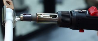
When checking a multi-core telephone cable, installers often use a dialing headset, for example TMG 1. Actually, these are two telephone handsets, one of which is connected to a 4.5 V battery. Such a simple device allows you not only to check the cable, but also to coordinate your actions during installation and testing.
Calling with a telephone handset
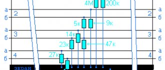
Use of ready-made core markings.
Testing a cable without using measuring devices became possible when, during its manufacturing process, they came up with the idea of twisting the cores in pairs, using two colors in a pair, and assigning a serial number to each pair. And if the cable, for example, is fourteen-core, then it will consist of seven multi-colored pairs with serial numbers from 1 to 7. The pictures show two pairs of cores of a sixty-core cable with serial numbers 3 and 24.
After cutting, such a cable is immediately marked using the serial numbers printed on its cores, and then, according to the diagram, it is connected to the terminal block. All this work is done by one person, which is very convenient and fast.
Insulation check
To test insulation with a megohmmeter or multimeter, the principle of continuity is the same as when searching for an electrical connection between the cable cores.
The testing algorithm is as follows:
- set the maximum range on the device - 2000 kOhm;
- connect the probes to the wires and see what the device display shows. Considering that the wires have a certain capacitance until it is charged, the readings may vary. After a few seconds, the device display can display the following values:
- one, this indicates that the insulation between the wires is normal;
- zero – there is a short circuit between the cores;
- some average readings, this can be caused either by a “leak” in the insulation or by electromagnetic interference. To determine the cause, switch the device to the maximum range of 200 kOhm. If the insulation is faulty, the display will display stable readings; if they change, then we can confidently talk about electromagnetic interference.
Attention! Before checking the insulation of the electrical wiring, it must be de-energized. The second important point is that when taking measurements, do not touch the probes with your hands, this can introduce errors.
Video: Wire continuity check - integrity check.
Checking electrical circuit parameters
When testing electrical circuits, you can test many of their parameters. This includes current, network voltage, and signal frequency. But to determine serviceability, you only need to ring the circuit for integrity and check the insulation resistance. Both can be done with a multimeter.
In order to know how to test electrical wiring with a multimeter, you need to correctly configure the measuring device and correctly perform the measurement steps. To check the integrity of the wire you need:
- Connect the black probe of the multimeter to the socket labeled COM, and the red one to the socket labeled U, Ω, Hz;
- The meter knob must be set to the 20 Ohm position;
- Connect the measuring contacts to both ends of the wire. If the ends are in different places in the room, you need to use a previously tested extension wire;
- The tester screen will display the value. If the value does not exceed 2 ohms, it means that the integrity of the wire is not compromised. If the readings are not at the same level or more than 8-10 ohms, then there is a break in the circuit.
In the same way, wires in a car and cables of various electronic devices are tested.
In addition to checking integrity, wires are tested for insulation resistance. This can also be done with a multimeter:
- The probes remain in the same holes as when checking integrity;
- The measurement mode selected is the same - resistance test;
- The measurement limit must be selected as large as 20 or 200 megaohms;
- Touch the probes to opposite conductors of the cable: phase and neutral or phase and screen. In a car, this is ground and signal wire;
- The screen should remain displaying infinity; if there is any value instead, it means there is a short circuit somewhere. Changing values indicate interference in the network.
In addition to ordinary wires, there are high-voltage wires that can withstand high current and voltage loads. These include spark plug wires in cars. The current that is required when starting the engine flows through them; this current reaches 80-150 amperes. Knowing how to test high-voltage wires with a multimeter is required when diagnosing car electronics. The ringing of these wires occurs according to the indicated diagram , with the difference that it is necessary to set a larger resistance measurement limit. Typically this limit should be set at 20 kilo-ohms.
After this, you need to find the ends of the wire and connect the multimeter probes to them. The resistance of this wire will be displayed on the device screen. It should be in the range from 1 to 10 kOhm.
In trucks, as well as in networks located in places subject to constant mechanical stress, conductors with a screen - armor or armored wires - are placed. The only special feature of the armored wire is the screen, made of durable metal. You can check the integrity and insulation of the armored wire in the same way as a regular one, you only need to have access to its ends and the screen outlet.
Read also: Hole for M20 main step
Finding the break point
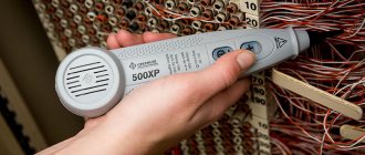
After a break in the electrical wiring has been discovered, it is necessary to localize the place where it happened. For dialing in this case, you can use a tone generator, for example, the Cable Tracker MS6812R or TGP 42. Such devices allow you to determine the location of the break with centimeter accuracy, as well as determine the route of hidden wiring; in addition, the devices have other useful functions.
Model MS6812R
Devices of this type include an audio signal generator and a sensor attached to an earphone or speaker. When the sensor approaches the place where the UTP cable pairs or electrical wiring wires are broken, the tone of the sound signal changes. When a tone test is performed, the wiring must be de-energized before connecting the sound generator, otherwise the device will be damaged.
Note that with the help of this device you can test both power and low-current cables, for example, check the integrity of twisted pair cables, radio wiring or communication lines. Unfortunately, such devices will not allow you to determine the correct connection; special equipment is used for this purpose - cable testers.
Wiring check
Testing conductors using a multimeter is functionally provided in most digital devices of this class. To set the dialing mode, just set the switch to the position marked with the “Buzzer” icon and prepare the measuring chain shown in the figure.
If current flows through the piece of wire being tested, the multimeter will produce an audible signal (buzzer). Naturally, to test a section of a circuit several meters long, you will need an additional wire used to expand the measuring circuit.
Another option for testing phase and neutral linear conductors of considerable length involves twisting them at the remote end of the electrical wiring.
In this case, to check the circuit for an open circuit, it is enough to connect the multimeter's test leads to the free contacts of those ends of the electrical line that are located closer to the device.
The last of the proposed options has the following advantages:
- using this method, you can use a multimeter to immediately test both wires of electrical wiring connected in a series chain;
- checking the wire in this way is much easier than the first way, since you can do without an additional segment that allows for extension of the measuring circuit.
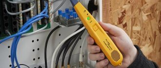
Cable testers
This class of devices allows you to check both the integrity of the cable and the correctness of its connection, which is very important for Internet provider networks. These can be simple devices that check crossover or complex devices on a PIC controller that have an ADC and a built-in multiplexer.
Multipurpose cable tester Pro'sKit MT-7051N on a microcontroller
Naturally, the cost of such devices does not encourage their household use.