Why do you need to calculate the cable cross-section?
The following requirements apply to electrical networks:
- safety;
- reliability;
- efficiency.
If the selected cross-sectional area of the wire is small, then the current loads on the cables and wires will be large, which will lead to overheating. As a result, an emergency may occur that will damage all electrical equipment and become dangerous to the life and health of people.
If you install wires with a large cross-sectional area, then safe use is ensured. But from a financial point of view there will be cost overruns. The correct choice of wire cross-section is the key to long-term safe operation and rational use of financial resources.
A separate chapter in the PUE is devoted to the correct selection of a conductor: “Chapter 1.3. Selection of conductors based on heating, economic current density and corona conditions.”
The cable cross-section is calculated based on power and current. Let's look at examples. To determine what wire cross-section is needed for 5 kW, you will need to use the PUE tables (“Electrical Installation Rules”). This directory is a regulatory document. It states that the choice of cable cross-section is made according to 4 criteria:
- Supply voltage (single-phase or three-phase).
- Conductor material.
- Load current, measured in amperes (A), or power - in kilowatts (kW).
- Cable location.
The PUE does not have a value of 5 kW, so you will have to choose the next larger value - 5.5 kW. For installation in an apartment today it is necessary to use copper wire. In most cases, installation is by air, so a cross-section of 2.5 mm² is suitable from the reference tables. In this case, the maximum permissible current load will be 25 A.
The above reference book also regulates the current for which the input circuit breaker (VA) is designed. According to the “Electrical Installation Rules”, with a load of 5.5 kW, the VA current should be 25 A. The document states that the rated current of the wire that is suitable for a house or apartment should be one step higher than that of the VA. In this case, after 25 A there is 35 A. The last value must be taken as the calculated one. A current of 35 A corresponds to a cross section of 4 mm² and a power of 7.7 kW. So, the choice of the cross-section of the copper wire according to power is completed: 4 mm².
To find out what wire cross-section is needed for 10 kW, we will again use the reference book. If we consider the case for open wiring, then we need to decide on the cable material and the supply voltage.
For example, for an aluminum wire and a voltage of 220 V, the nearest higher power will be 13 kW, the corresponding cross-section is 10 mm²; for 380 V the power will be 12 kW and the cross-section will be 4 mm².
A few basic concepts
Why is it necessary to calculate the cross-section of wires? Is it possible to limit the selection “by eye”?
No, you can’t, because it’s not at all difficult to go to two extremes:
- A conductor of insufficient cross-section begins to overheat greatly. This leads to melting of the wiring insulation, creating conditions for spontaneous combustion and short circuits. All this causes destructive fires, often accompanied by human tragedies.
- Conductors of excess diameter, of course, do not pose such dangers. But they are also significantly more expensive (especially if we are talking about copper cables) and are not so convenient to use. The result is completely unjustified material and labor costs.
So we should be guided by the principle of reasonable sufficiency. Moreover, anyone who has at least a little understanding of the basics of mathematics and physics can make the necessary calculations.
To begin with, let us recall some concepts that are probably already well known to many. But just so that in the further presentation there are no discrepancies.
Basic Rules
How to calculate a cable by current, voltage and length. Cables, as you know, come in different sections, materials and with different numbers of cores. Which one should you choose so as not to overpay, and at the same time ensure the safe, stable operation of all electrical appliances in the house? To do this, it is necessary to calculate the cable. The cross section is calculated by knowing the power of the devices powered from the network and the current that will flow through the cable. You also need to know a few other wiring parameters.
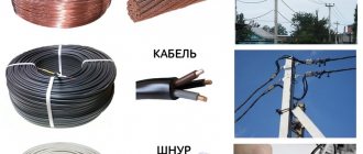
When laying electrical networks in residential buildings, garages, and apartments, rubber or PVC insulated cables designed for a voltage of no more than 1 kV are most often used. There are brands that can be used outdoors, indoors, in walls (grooves) and pipes. Usually this is a VVG or AVVG cable with different cross-sectional areas and number of cores. PVA wires and SHVVP cords are also used to connect electrical appliances.
After calculation, the maximum permissible cross-section value is selected from a number of cable grades.
Basic recommendations for choosing a cross-section are found in the Electrical Installation Rules (PUE). The 6th and 7th editions have been released, which describe in detail how to lay cables and wires, install protection, distribution devices and other important points.
For violation of the rules, administrative fines are provided. But the most important thing is that violation of the rules can lead to failure of electrical appliances, fire of wiring and serious fires. Fire damage is sometimes measured not in monetary terms, but in human casualties.
Calculation using an online calculator
Numerous online calculators offer automatic cross-section calculations. How to calculate the wire cross-section using such a calculator? A popular algorithm suggests entering several known characteristics: type of current (AC or DC), conductor material (Cu or Al), total power of the connected load (in kW), rated voltage. Also, for AC systems, when calculating the cross-section, it is important to know the type of supply - single-phase or three-phase.
The method of laying the cable also affects the maximum permissible load due to different heat dissipation conditions (open installation contributes to better cooling of the cable compared to a cable channel, and in the ground the conductor heats up the least and is able to pass higher values of long-term rated current).
The number of loaded wires in a bundle will be different for direct and alternating current, as well as for single-phase and three-phase alternating current systems. So, all wires are considered loaded in a direct current network, but with alternating current the situation is different:
- in a 1-phase network, the phase and neutral wires are loaded;
- in 3-phase - only phase ones (neutral protective and working conductors are not taken into account).
That is, examples of loaded wires in a bundle during calculation can be as follows: two, three or four wires in separate insulation, two or three wires in general insulation, etc.
Please note that the online calculator for calculating the cross section offers only preliminary and approximate results. The obtained values cannot be used in real power supply system projects without professional evaluation.
Cable selection
It is best to make internal wiring using copper wires. Although aluminum ones are not inferior to them. But there is one nuance here, which is associated with the correct connection of sections in the distribution box. As practice shows, connections often fail due to oxidation of the aluminum wire.
Another question is which wire to choose: single-core or stranded? Single-core has better current conductivity, so it is recommended for use in household electrical wiring. Multicore has high flexibility, which allows it to be bent in one place several times without compromising quality.
Single-core and multi-core wires
There is often confusion with this issue, including in articles published on Internet sites.
So, one wire can be used as a conductor in wires and cables - from the point of view of electrical conductivity, this is the best option.
But to achieve flexibility in cable products, it is necessary to use more complex structures - many thin wires, usually twisted into a “pigtail”. The more such wires, the more flexible the conductor becomes.
However, this should not be confused with stranded wire. A separate conductor means a separate conductor. To make it clearer, look at the illustration.
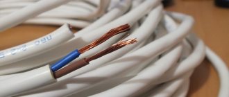
The picture below shows examples of single-core wire. It’s just that on the left side there is a rigid single-wire version, and on the right side there is a more flexible multi-wire version.
Both left and right are single-core wires.
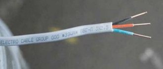
If a wire (cable) structurally combines two or more conductors isolated from each other, it becomes two-core, three-core, etc. But it can also remain single- or multi-wire.
Double stranded wire
The situation is similar with cables. By definition, a cable is a structure of several conductors isolated from each other, enclosed in a common insulating and protective sheath. But conductors can also be single- or multi-wire.
Three-core power cables - solid or stranded
Rigid single-wire products are good for fixed sections of wiring, for example, embedded in walls. Stranded wires and cables are great for areas where mobility is needed - typical examples include power cords for household appliances and lighting fixtures.
So, all subsequent calculations will be carried out for the cross-section of the wire or cable core.
When assessing the conditions for the location of wires in the future, there may be options when you have to imagine the difference, for example, between three single-core wires stretched in one pipe, or one three-core cable.
Copper or aluminum
In the USSR, most residential buildings were equipped with aluminum wiring; this was a kind of norm, standard, and even dogma. No, this does not mean at all that the country was poor and there was a shortage of copper. Even in some cases it's the other way around.
But apparently the designers of electrical networks decided that they could save a lot economically if they used aluminum rather than copper. Indeed, the pace of construction was enormous; just remember the Khrushchev buildings, in which half of the country still lives, which means the effect of such savings was significant. There is no doubt about this.
However, today the realities are different, and aluminum wiring is not used in new residential premises, only copper. This is based on the rules of the PUE, clause 7.1.34 “Cables and wires with copper conductors should be used in buildings...”.
So, we strongly do not recommend that you experiment and try aluminum. Its disadvantages are obvious. Aluminum strands cannot be soldered and are also very difficult to weld; as a result, the contacts in the junction boxes may break over time. Aluminum is very fragile, two or three bends and the wire falls off.
There will be constant problems connecting it to sockets and switches. Again, if we talk about conducted power, then a copper wire with the same cross-section for aluminum is 2.5 mm2. allows a continuous current of 19A, and for copper 25A. Here the difference is more than 1 kW.
So let’s repeat it again - only copper! Further, we will proceed from the fact that we are calculating the cross-section for a copper wire, but in the tables we will also give values for aluminum. You never know.
Open and closed wiring
As we all know, when current passes through a conductor, it heats up. The higher the current, the more heat generated. But, when the same current passes through conductors with different cross-sections, the amount of heat generated changes: the smaller the cross-section, the more heat is released.
In this regard, when the conductors are laid open, its cross-section may be smaller - it cools down faster, since heat is transferred to the air. In this case, the conductor cools down faster and the insulation does not deteriorate. When the gasket is closed, the situation is worse - heat is removed more slowly. Therefore, for closed installations - in cable ducts, pipes, in the wall - it is recommended to take a cable with a larger cross-section.
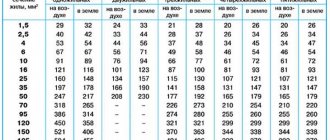
The choice of cable cross-section, taking into account the type of installation, can also be made using the table. The principle was described before, nothing changes. There's just one more factor to consider.
Selection of cable cross-section depending on power and type of installation
And finally, some practical advice. When going to the market to buy a cable, take a caliper with you. Too often the stated cross-section does not coincide with reality. The difference can be 30-40%, which is a lot. What does this mean for you? Burnout of wiring with all the ensuing consequences. Therefore, it is better to check right on the spot whether a given cable actually has the required core cross-section (the diameters and corresponding cable cross-sections are in the table above). You can read more about determining the cable cross-section by its diameter here.
What you need to know
The main indicator by which a wire is calculated is its long-term permissible current load. Simply put, this is the amount of current that it is capable of passing for a long time.
To find the rated current value, you need to calculate the power of all connected electrical appliances in the house. Let's consider an example of calculating the wire cross-section for an ordinary two-room apartment.
Table of power consumption/current strength of household electrical appliances Electrical appliancePower consumption, W Current strength, A
| Washing machine | 2000 – 2500 | 9,0 – 11,4 |
| Jacuzzi | 2000 – 2500 | 9,0 – 11,4 |
| Electric floor heating | 800 – 1400 | 3,6 – 6,4 |
| Stationary electric stove | 4500 – 8500 | 20,5 – 38,6 |
| microwave | 900 – 1300 | 4,1 – 5,9 |
| Dishwasher | 2000 – 2500 | 9,0 – 11,4 |
| Freezers, refrigerators | 140 – 300 | 0,6 – 1,4 |
| Electric meat grinder | 1100 – 1200 | 5,0 – 5,5 |
| Electric kettle | 1850 – 2000 | 8,4 – 9,0 |
| Electric coffee maker | 630 – 1200 | 3,0 – 5,5 |
| Juicer | 240 – 360 | 1,1 – 1,6 |
| Toaster | 640 – 1100 | 2,9 – 5,0 |
| Mixer | 250 – 400 | 1,1 – 1,8 |
| Hairdryer | 400 – 1600 | 1,8 – 7,3 |
| Iron | 900 –1700 | 4,1 – 7,7 |
| Vacuum cleaner | 680 – 1400 | 3,1 – 6,4 |
| Fan | 250 – 400 | 1,0 – 1,8 |
| TV | 125 – 180 | 0,6 – 0,8 |
| Radio equipment | 70 – 100 | 0,3 – 0,5 |
| Lighting devices | 20 – 100 | 0,1 – 0,4 |
Once the power is known, the calculation of the cross-section of a wire or cable comes down to determining the current strength based on this power. You can find the current strength using the formula:
1) Formula for calculating current for a single-phase 220 V network:
current calculation for a single-phase network
where P is the total power of all electrical appliances, W; U—mains voltage, V; CI = 0.75 - simultaneity coefficient; cos for household electrical appliances - for household electrical appliances. 2) Formula for calculating the current in a three-phase 380 V network:
current calculation for a three-phase network
Knowing the magnitude of the current, the wire cross-section is found from the table. If it turns out that the calculated and tabulated current values do not coincide, then in this case the nearest larger value is selected. For example, the calculated current value is 23 A, we select the nearest larger one from the table, 27 A - with a cross-section of 2.5 mm2.
Which wire is better to use
Today, for installation of both open and hidden electrical wiring, copper wires are, of course, very popular.
- Copper, compared to aluminum, is more effective:
- it is stronger, softer and does not break in places of inflection compared to aluminum;
- less susceptible to corrosion and oxidation. When connecting aluminum in a junction box, the twist points oxidize over time, which leads to loss of contact;
- The conductivity of copper is higher than that of aluminum; with the same cross-section, a copper wire can withstand a higher current load than aluminum.
The disadvantage of copper wires is their high cost. Their cost is 3-4 times higher than aluminum ones. Although copper wires are more expensive, they are still more common and popular in use than aluminum wires.
Choose by power
Before choosing a cable cross-section based on power, you need to calculate its total value and make a list of electrical appliances located in the territory to which the cable is laid. The power must be indicated on each device; the corresponding units of measurement will be written next to it: W or kW (1 kW = 1000 W). Then you will need to add up the power of all equipment and get the total.
If you select a cable to connect one device, then only information about its energy consumption is sufficient. You can select wire cross-sections based on power in the PUE tables.
Table 1. Selection of wire cross-section by power for cable with copper conductors
| Conductor cross-section, mm² | For cable with copper conductors | |||
| Voltage 220 V | Voltage 380 V | |||
| Current, A | power, kWt | Current, A | power, kWt | |
| 1,5 | 19 | 4,1 | 16 | 10,5 |
| 2,5 | 27 | 5,9 | 25 | 16,5 |
| 4 | 38 | 8,3 | 30 | 19,8 |
| 6 | 46 | 10,1 | 40 | 26,4 |
| 10 | 70 | 15,4 | 50 | 33 |
| 16 | 85 | 18,7 | 75 | 49,5 |
| 25 | 115 | 25,3 | 90 | 59,4 |
| 35 | 135 | 29,7 | 115 | 75.9 |
| 50 | 175 | 38.5 | 145 | 95,7 |
| 70 | 215 | 47,3 | 180 | 118,8 |
| 95 | 260 | 57,2 | 220 | 145,2 |
| 120 | 300 | 66 | 260 | 171,6 |
Table 2. Selection of wire cross-section by power for cable with aluminum conductors
| Conductor cross-section, mm² | For cable with aluminum conductors | |||
| Voltage 220 V | Voltage 380 V | |||
| Current, A | power, kWt | Current, A | power, kWt | |
| 2,5 | 20 | 4,4 | 19 | 12,5 |
| 4 | 28 | 6,1 | 23 | 15,1 |
| 6 | 36 | 7,9 | 30 | 19,8 |
| 10 | 50 | 11,0 | 39 | 25,7 |
| 16 | 60 | 13,2 | 55 | 36,3 |
| 25 | 85 | 18,7 | 70 | 46,2 |
| 35 | 100 | 22,0 | 85 | 56,1 |
| 50 | 135 | 29,7 | 110 | 72,6 |
| 70 | 165 | 36,3 | 140 | 92,4 |
| 95 | 200 | 44,0 | 170 | 112,2 |
| 120 | 230 | 50,6 | 200 | 132,2 |
In addition, you need to know the network voltage: three-phase corresponds to 380 V, and single-phase - 220 V.
The PUE provides information for both aluminum and copper wires. Both have their advantages and disadvantages. Advantages of copper wires:
- high strength;
- elasticity;
- oxidation resistance;
- electrical conductivity is greater than that of aluminum.
The disadvantage of copper conductors is their high cost. In Soviet houses, aluminum electrical wiring was used during construction. Therefore, if a partial replacement occurs, it is advisable to install aluminum wires. The only exceptions are those cases when new wiring is installed instead of all the old wiring (up to the switchboard). Then it makes sense to use copper. It is unacceptable for copper and aluminum to come into direct contact, as this leads to oxidation. Therefore, a third metal is used to connect them.
You can independently calculate the wire cross-section according to power for a three-phase circuit. To do this, you need to use the formula: I=P/(U*1.73), where P is power, W; U—voltage, V; I - current, A. Then the cable cross-section is selected from the reference table depending on the calculated current. If the required value is not there, then the closest one is selected, which exceeds the calculated one.
How to calculate by current
The amount of current passing through a conductor depends on the length, width, resistivity of the latter and on temperature. When heated, the electric current decreases. Reference information is given for room temperature (18°C). To select the cable cross-section by current, use the PUE tables (PUE-7 clause 1.3.10-1.3.11 PERMISSIBLE CONTINUOUS CURRENTS FOR WIRES, CORDS AND CABLES WITH RUBBER OR PLASTIC INSULATION).
Table 3. Electric current for copper wires and cords with rubber and PVC insulation
| Conductor cross-sectional area, mm² | Current, A, for wires laid | |||||
| open | in one pipe | |||||
| two single-core | three single-core | four single-core | one two-wire | one three-wire | ||
| 0,5 | 11 | — | — | — | — | — |
| 0,75 | 15 | — | — | — | — | — |
| 1 | 17 | 16 | 15 | 14 | 15 | 14 |
| 1,2 | 20 | 18 | 16 | 15 | 16 | 14,5 |
| 1,5 | 23 | 19 | 17 | 16 | 18 | 15 |
| 2 | 26 | 24 | 22 | 20 | 23 | 19 |
| 2,5 | 30 | 27 | 25 | 25 | 25 | 21 |
| 3 | 34 | 32 | 28 | 26 | 28 | 24 |
| 4 | 41 | 38 | 35 | 30 | 32 | 27 |
| 5 | 46 | 42 | 39 | 34 | 37 | 31 |
| 6 | 50 | 46 | 42 | 40 | 40 | 34 |
| 8 | 62 | 54 | 51 | 46 | 48 | 43 |
| 10 | 80 | 70 | 60 | 50 | 55 | 50 |
| 16 | 100 | 85 | 80 | 75 | 80 | 70 |
| 25 | 140 | 115 | 100 | 90 | 100 | 85 |
| 35 | 170 | 135 | 125 | 115 | 125 | 100 |
| 50 | 215 | 185 | 170 | 150 | 160 | 135 |
| 70 | 270 | 225 | 210 | 185 | 195 | 175 |
| 95 | 330 | 275 | 255 | 225 | 245 | 215 |
| 120 | 385 | 315 | 290 | 260 | 295 | 250 |
| 150 | 440 | 360 | 330 | — | — | — |
| 185 | 510 | — | — | — | — | — |
| 240 | 605 | — | — | — | — | — |
| 300 | 695 | — | — | — | — | — |
| 400 | 830 | — | — | — | — | — |
A table is used to calculate aluminum wires.
Table 4. Electric current for aluminum wires and cords with rubber and PVC insulation
| Conductor cross-sectional area, mm² | Current, A, for wires laid | |||||
| open | in one pipe | |||||
| two single-core | three single-core | four single-core | one two-wire | one three-wire | ||
| 2 | 21 | 19 | 18 | 15 | 17 | 14 |
| 2,5 | 24 | 20 | 19 | 19 | 19 | 16 |
| 3 | 27 | 24 | 22 | 21 | 22 | 18 |
| 4 | 32 | 28 | 28 | 23 | 25 | 21 |
| 5 | 36 | 32 | 30 | 27 | 28 | 24 |
| 6 | 39 | 36 | 32 | 30 | 31 | 26 |
| 8 | 46 | 43 | 40 | 37 | 38 | 32 |
| 10 | 60 | 50 | 47 | 39 | 42 | 38 |
| 16 | 75 | 60 | 60 | 55 | 60 | 55 |
| 25 | 105 | 85 | 80 | 70 | 75 | 65 |
| 35 | 130 | 100 | 95 | 85 | 95 | 75 |
| 50 | 165 | 140 | 130 | 120 | 125 | 105 |
| 70 | 210 | 175 | 165 | 140 | 150 | 135 |
| 95 | 255 | 215 | 200 | 175 | 190 | 165 |
| 120 | 295 | 245 | 220 | 200 | 230 | 190 |
| 150 | 340 | 275 | 255 | — | — | — |
| 185 | 390 | — | — | — | — | — |
| 240 | 465 | — | — | — | — | — |
| 300 | 535 | — | — | — | — | — |
| 400 | 645 | — | — | — | — | — |
In addition to the electric current, you will need to select the conductor material and voltage.
For an approximate calculation of the cable cross-section for current, it must be divided by 10. If the resulting cross-section is not in the table, then it is necessary to take the nearest larger value. This rule is only suitable for cases where the maximum permissible current for copper wires does not exceed 40 A. For the range from 40 to 80 A, the current must be divided by 8. If aluminum cables are installed, then it must be divided by 6. This is because for To ensure equal loads, the thickness of the aluminum conductor is greater than that of copper.
Calculation of cable cross-section by power and length
The cable length affects the voltage loss. Thus, the voltage at the end of the conductor may decrease and be insufficient to operate the electrical appliance. For household electrical networks, these losses can be neglected. It will be enough to take a cable 10-15 cm longer. This reserve will be used for switching and connection. If the ends of the wire are connected to the shield, then the spare length should be even greater, since circuit breakers will be connected.
When laying cables over long distances, voltage drop must be taken into account. Each conductor is characterized by electrical resistance. This parameter is affected by:
- Wire length, unit of measurement - m. As it increases, losses increase.
- Cross-sectional area, measured in mm². As it increases, the voltage drop decreases.
- Material resistivity (reference value). Shows the resistance of a wire measuring 1 square millimeter per 1 meter.
The voltage drop is numerically equal to the product of resistance and current. It is acceptable that the specified value does not exceed 5%. Otherwise, you need to take a cable with a larger cross-section. Algorithm for calculating wire cross-section based on maximum power and length:
- Depending on the power P, voltage U and cosph coefficient, we find the current using the formula: I=P/(U*cosph). For electrical networks that are used in everyday life, cosф = 1. In industry, cosф is calculated as the ratio of active power to total power. The latter consists of active and reactive powers.
- Using PUE tables, the current cross-section of the wire is determined.
- We calculate the resistance of the conductor using the formula: Ro=ρ*l/S, where ρ is the resistivity of the material, l is the length of the conductor, S is the cross-sectional area. It is necessary to take into account the fact that current flows through the cable not only in one direction, but also back. Therefore, the total resistance: R = Ro*2.
- We find the voltage drop from the relationship: ΔU=I*R.
- We determine the voltage drop as a percentage: ΔU/U. If the obtained value exceeds 5%, then select the nearest larger cross-section of the conductor from the reference book.
Continuous-permissible current loads of cables
Currents flowing through the cable heat the conductor. This does not apply to the beneficial effects of current, such as heating the filament of a light bulb or an electric stove. Therefore, we do not take this action into account when calculating the total power consumption. However, you should not forget about the energy consumption for heating the wires, as this can lead to dire consequences.
The amount of current flowing through the wires depends on the power of the consumer devices, since the power released on the wires themselves is negligible - due to the low resistivity of the metals used for the wire and in the wiring cable. Current flows only when we plug in devices. In this case, the total current at each moment in time is determined only by the power of the devices (related to the resistance) consuming energy in the network at that particular moment in time. But when calculating the network by current and power, it is always necessary to take only situations when all consuming devices are turned on at the same time. Only this approach makes it possible to insure against all possible overloads. But that's not all. At the moment of switching on, many devices consume the so-called starting current, which can be 10–20 percent higher in consumption from the stationary operation of the device. For some devices, this is due to the difficulty of starting - accelerating massive rotors, creating operating pressure drops, and so on. Therefore, when performing the calculation, it is also necessary to make an adjustment for this.
Permissible continuous current for cables
Current-carrying wires always heat up when exposed to current. The only question is the amount of heat generated. On the one hand, it depends on the flowing current, the resistivity of the conductor material, its cross-section, on the other hand, on the factors of heat removal in the conditions of the passage of wires: on the number of wires and their proximity, insulation, which prevents heat removal, the presence of boxes or channels into which The cable is tucked in, the wiring is hidden. And in general, from the climatic factors acting on the cable in the places where the wires pass: ventilation, open space, and so on.
Wiring quality and aging
As a result of all these numerous factors, a wire that is systematically heated by the current passing through it, from a safety point of view, can be:
- Reliable carrier of current and voltage. For such a wire, the period of future trouble-free operation can be considered unlimited.
- Old or aging electrical energy carrier. The quality of the wire has decreased during operation, the insulation has deteriorated, the joints and connections of the wires have lost some of their conductivity. Wire aging tends to accumulate over time and contribute to an increase in the rate of aging and an increase in negative factors.
- Dangerous electrical wiring. The operating mode is such that accidents are likely. This is expressed in increased heating of wires at normal current, uneven heating due to deterioration of insulation, oxidation of contacts, deterioration in the uniformity of wire cross-section due to oxidation, which is natural for metals. Unevenness also tends to enhance aging and locally degrade quality.
Temperature is therefore a very important indicator of the safety of electrical wiring. In addition, the temperature regime itself can deteriorate the wiring, and if the maximum threshold is exceeded, lead to accidents. As a result, the permissible current loads of the cables must be reduced.
For example, there is a rule that every 8° of excess current heating of the cable speeds up the processes (both chemical and physical) in the material by a factor of two. This affects the performance of the conductor (especially aluminum) and degrades the performance of the insulator.
Insulation and temperature
Insulation as a result of heating can itself become a source of dangerous and harmful factors. For example, PVC behaves like this when the temperature increases:
- 80 °C - softening;
- 100 °C - release of HCl (volatile harmful gas, hydrogen chloride, which when dissolved in water becomes hydrochloric acid). As the temperature rises, the process intensifies. At 160 °C 50% of it will already be released, at 300 °C - 85%;
- 210 °C - melting;
- 350 °C - the PVC carbon base begins to ignite.
This applies to hard PVC; soft PVC contains many plasticizer additives that volatilize and can catch fire even at 200 °C.
Softening, especially melting, conceals another danger - current-carrying wires may come closer together, which usually leads to a short circuit and fire.
For safety reasons, the upper temperature limit of the wires through which electric current passes was set at 65 °C. This is at an ambient air temperature of 25 °C, and a ground temperature of 15 °C.
The task of maintaining such a heating rate is to select, for all the variety of conditions, cross-sections for wires made of different materials used in electrical engineering that are sufficient for the safe passage of current, that is, without heat accumulation.
A prerequisite is that the permissible long-term current for the cables is meant, and not short-term overloads.
Wires and cables should be protected from sudden overcurrents by circuit breakers on the power panel.
Moreover, their ratings are selected so that they are higher than the currents that arise during short-term, but permissible overloads, but lower than the overvoltages that are dangerous for the network.
Wiring structure of the consuming network
The consumption network consists of several groups of consumers. Each of them has its own nature of loads and current regime, therefore, the wiring must comply with safety rules. The most important rule: high loadability must be ensured where it is loaded. That is, the input wires that bear the entire burden of consumption in the network must be the largest in cross-section, since through them the energy is consumed for the entire power of the loads in the network in question.
Example. Calculation of cable cross-section for residential consuming network
The table shows consumption devices
Bus current from the total power formula
Total power formula
with KI, utilization factor equal to 75% and cos j = 1,
is obtained in the range I = 41–81 A. For wiring that takes into account any possible options for the power of connected electrical appliances, you should take the upper value and a margin for the future of about 10–20%. Therefore, we accept a maximum current of 100 A.
Perhaps such a load will place a heavy burden on the buses of the home network, and the electricity supply organization will not allow so many consumers at once, but the choice of wires should not depend on such “political” issues. Moreover, wiring in old houses already demonstrates the short-sightedness of previous restrictions.
The cross-section of the buses supplied to the apartments must be taken as a given. If we do the wiring in the apartment ourselves, then we divide it into several subnetworks according to groups of current consuming devices. Each subnetwork will be powered separately from the power panel buses. And it must be performed with the expectation of maximum consumption in this particular subnet.
PUE - rules for electrical installations
To regulate safety relating to everything related to electricity, there is a system of rules that began to be developed from the very beginning of the use of electricity (1899, the First All-Russian Electrotechnical Congress) and were brought into a system close to the modern one, immediately after the Great Patriotic War in 1946– 1949 And they exist and continue to be developed now - in Russia, Belarus and Ukraine.
Electrical safety is a very serious matter, despite differences of opinion elsewhere. For example, we also provide for fines for non-compliance with the rules for the installation of electrical installations for citizens, officials and entrepreneurs and for legal entities.
What concerns electrical wiring safety is collected in section 1 in chapter 3.
The tables show the permissible continuous current for cables for a variety of wire options, metals (different resistivities), insulation, nature (single-core - stranded), wire cross-section, as well as cable laying methods.
The full text of Chapter 3 from Section 1 of the 7th edition of the PUE is available in the following file. The permissible continuous current for cables in them is presented in tables 3.1.7.4 – 3.1.7.11.
For our example, we will build a table, dividing all consumers into groups, in each group we will calculate the total power and current and find from the PUE the corresponding cable cross-section for copper and aluminum.
In our case, we will select subnetworks and calculate the total power and maximum current for each of them. From the PUE we will select the wire cross-section for copper wires and aluminum:
It turns out that a wire cross-section of 1 mm2 copper or 2 mm2 aluminum is suitable for the lighting network.
For an outlet network with low consumption (residential premises), 1.5 and 2.5 mm2, respectively.
Two outlet subnetworks with a significant level of consumption - in the kitchen and bathroom - gave 4 and 5–6 mm2.
Individual consumers can be powered by separate wiring with individual calculation of current and cross-section.
domelectrik.ru
Selecting the wire cross-section based on the number of consumers
What I also wanted to say is that it is better to use several independent power lines for each room in a room or apartment. Thus, you will not use a wire with a cross-section of 10 mm 2 for the entire apartment, routed to all rooms, from which there are taps.
Such a wire will come to the input machine, and then from it, in accordance with the power of the consumed load, selected wire sections will be routed for each of the rooms.
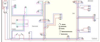
Typical electrical wiring diagram for an apartment or house with an electric stove (indicating the cable cross-section for electrical appliances)
Core diameter and cross-section
To calculate the cross-section of a monolithic core by diameter you need:
- Remove insulation from a small section of the cable.
- Using a caliper or micrometer, measure the diameter of the core without taking into account the insulation.
- Substitute into the formula:
S = πR2 = (πD2)/4,
in which π = 3.14 (constant);
R is the radius of the circle;
D is the diameter of the circle.
The formula is extremely simple, the main thing is not to confuse the diameter with the radius. Radius is the distance from the center of the circle to its boundary. Diameter is the largest distance between the boundaries of a circle. The diameter is equal to two radii.
How to calculate the cross-section for a multi-core cable? Let’s make a reservation right away that you can’t just grab the entire bundle of wires with a caliper and measure it in one go. In this delicate process, even the air gap matters. You need to measure the diameter of one core, and then multiply it by the number of cores in the wire/cable. And substitute the section formula described above.
An important point: there is a wire twist factor, which for cables with stranded conductors of class 5 is equal to 1.053.
In practice, it often turns out that the nominal and actual cross-sections of the core do not coincide. That is, the numbers indicated on the cable product markings differ from the actual values measured using a caliper and substitution into the cross-section formula.
If the manufacturing plant adheres to GOST 22483-2012 entitled “Current-carrying conductors for cables, wires and cords,” then they indicate this on the products. Sometimes cables and wires do not comply with the State Standard, but are produced in accordance with Specifications. Experienced electricians say that confidence in such products is lower.
