Sections of the article:
Grounding wire - cable cross-section and grade
Grounding your home has a number of benefits. Firstly, residents will be at least somehow protected from electric shock in the event of a leak. Secondly, the operation of some electrical appliances will be safer.
As a rule, there are no problems with materials for installing the simplest grounding. This is a metal corner or fitting, as well as a ready-made modular grounding kit.
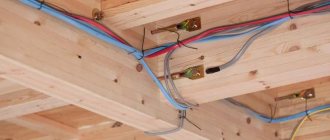
Most often, those who decide to do their own grounding in the house are wondering which wire to use. Let's say the ground electrodes are buried in the ground and connected by a metal strip.
Further, from the strip that is supplied to the house, the grounding wire extends. So, you should know what cross-section of the wire should be, and what cable can be used for these purposes. This article on the site will discuss this most important issue.
What should the ground wire be like?
The requirements for the grounding wire may be different, it all depends on the characteristics of the soil, the goals set for it, operational characteristics, as well as the electrical installations themselves.
The main criterion that they all must meet is the ability to pass an electric current of the same strength as when a short circuit occurs.
The remaining criteria are different; they will be classified according to the following criteria:
- The number of cores of the wire and its flexibility class. To connect electrical installations to the grounding wire, solid and single-wire wires are used.
- In the event that the doors of the panels in which the distribution of wires, cells, and grounding blocks occur often need to be opened or closed, then other wires are used for this - multi-core or stranded. They are more resistant to frequent flexion and extension.
- Location. This wire can run either as a separate line or be located in a cable and wire product.
- Presence or absence of insulation. This condition is necessary if the wire needs to be used in both open and closed modes.
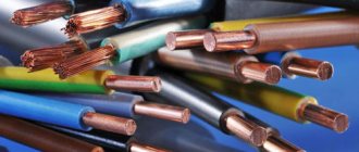
- Conductive material used. The choice of core located in the wire (copper, steel, aluminum) depends on the physical properties of the conductor and its chemical resistance.
For example, copper has the lowest resistivity and excellent anti-corrosion characteristics compared to other substances (aluminum, steel).
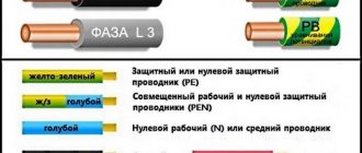
Conductor insulation coating colors
It is necessary to color-code grounding, phase and neutral cables in accordance with the requirements of the PUE. The document establishes color differences for grounding in the electrical panel, as well as for zero and phase. Understanding the insulation color code eliminates the need to decipher letter markers.
Ground wire color
In the Russian Federation, the European standard IEC 60446:2007 has been in force since January 1, 2011. It notes that the grounding has only yellow-green insulation. If an electrical circuit is drawn up, the ground should be designated as PE.
There is a grounding core only in cables with 3 cores.
PEN conductors used in old buildings combine ground and neutral conductors. The insulating coating in this case has a blue grounding color and yellow-green cambrics at the connection points and ends of the wire. In some cases, the reverse marking was used - yellow-green color zeroing with blue tips.
The ground and neutral conductors of PEN cables are thinner than the phase conductors.
The organization of protective grounding is a prerequisite for creating an electrical network in residential and industrial buildings. Its necessity is indicated in the PUE and GOST 18714-81. Standards state that zero grounding should have the lowest resistance. To avoid confusion, use color markings for the cables.
Color designation of zero working contacts
Color of wires in electrical wiring
In order not to confuse where the phase is and where the zero is, instead of the letters L and N, they are guided by the colors of the cables. Electrical standards note that the neutral is blue, light blue, blue-white, regardless of the number of wires.
Zero can be designated by the Latin letter N, which is read as a minus in the diagram. The reason for reading is the participation of zero in the closure of the electrical circuit.
Phase wire colors
A phase is a live line that, if touched carelessly, can lead to electric shock. Novice craftsmen often have difficulty finding a cable. The phase is indicated by black, brown, cream, red, orange, pink, purple, gray and white.
The alpha phase index is L. It is used where the wires are not color coded. When connecting a cable to several phases, a serial number or Latin letters A, B, C are placed next to the letter L. The phase is also often marked as plus.
The phase wire cannot be blue, cyan, green or yellow.
Types of ground wires
Among the most popular markings of grounding wires that are allowed to be used for conducting a grounding conductor, the following types are distinguished.
VVG. This type has a copper core and is equipped with an insulation layer and an additional outer coating of polymer PVC.
- Produced in both mono- and multi-core versions.
- The flexibility class of this wire is 1.2. Used in electrical networks from 0.66 to 6 kV.
- The temperature range at which it can be used is from minus to plus fifty degrees Celsius.
- A cable with three to five cores can be equipped with a neutral and a grounding conductor.
NUM. The wire is quite elastic, flexibility class from one to five, in the middle of which there is a copper conductor.
- It is produced in PVC insulation and an additional sheath, between which there is a non-flammable rubber mixture.
- It is allowed to be used in electrical networks in which the voltage reaches 0.66 kV. The performance of the wire is maintained from -50 to +50 degrees Celsius.
- There is one thing - it needs protection from ultraviolet radiation.
The next group of wires, marked PV, has a multi-wire copper core insulated with a double layer of PVC, which does not burn. They are designed for AC electrical voltage up to 0.45 kV. and constant up to one kilowatt.
They differ from each other by the flexibility class, which is indicated in the marking of the wires and the grounding conductor:
- Flexibility class 3 – has excellent water resistance and is not susceptible to vapor, condensation, or mold. Remains operational from minus seventy to plus sixty degrees Celsius. That is why it is used in rooms with high humidity levels, for example, a bathhouse, open space;
- Flexibility class 6 – the characteristics are similar to the previous type of wire, only a little more flexible;
- Flexibility class C is quite flexible in this category of connecting products. Flexibility class from two to five. It has a copper multi-wire electrical conductor located in low-flammable PVC insulation and an additional coating. It is designed for electrical voltages from 0.38 to 0.66 kilowatts. Performance is maintained - from minus 25 to plus 40 degrees Celsius.
- ESUY is the most flexible of all cable types offered. It has a conductor consisting of a large number of tinned copper wires located in a copper wire braid, as well as a sheath made of transparent non-flammable polymer PVC. This type of cable is used at temperatures from -5 to + 70 degrees Celsius.
It is used for grounding portable equipment during repair work and maintenance; it is also used in power plants with high voltage, in railway transport in traction units and, when necessary, to align electrical machine components.
In addition to the listed categories of cables, other brands are also used, for example, MG (without insulation), VBBShV (armored), ShVVP (lace). When choosing cable markings, it is worth taking into account the requirements set out above and, of course, the standards of PUE, SNiPs, SP.
Letter marking of wires
Standards for letter and color marking of wires
For household and industrial power lines, insulated wires with internal conductive conductors are used. Products differ depending on the color of the insulating coating and markings. The designation of phase and zero in electrics speeds up repair and installation work.
Marking of cables in electrical installations under voltage up to 1000 V is regulated by GOST R 50462-2009:
- in clause 6. 2.1 it is indicated that the neutral conductor is marked as N;
- clause 6.2.2. states that the protection wire with grounding is designated PE;
- in paragraph 6.2.12 it is said that in electrics L is a phase.
Understanding the markings simplifies installation work in commercial, residential and administrative buildings.
L – phase designation
Designation L and N in electrics
In an alternating current network, the phase wire is energized. Translated from English, the word Line means an active conductor, line, and is therefore marked with the letter L. Phase conductors must be covered with colored insulation, since, being exposed, they can cause burns, human injuries, fire or failure of various equipment.
N – alphabetic symbol of zero
The sign of a neutral or neutral working cable is N, from the abbreviation of the terms neutral or NULL. When drawing up a diagram, the zero switching terminals in a single-phase or three-phase network are marked this way.
The word “zero” is used only in the CIS countries; throughout the world the core is called neutral.
PE – grounding index
Grounding marking
If the wiring is grounded, the letter marking PE is used. In English, the meaning of Protective Earthing is translated as grounding wire. Clamps and contacts for switching with ground zero will be designated similarly.
How to choose a section type
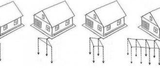
To select the correct cross-section of grounding wires, you need to focus on the capabilities of the electrical network. The grounding loop, as well as the conductor, are not subject to constant loads, unlike phase and zero.
That is why the cross-section of the grounding wire, according to clause 1.7.126 of the PUE, should be determined as follows:
- For a 16 mm2 power cable, the same grounding cross-section is taken;
- Power cable from 16 to 35 mm2 will require 16mm2;
- For a power cable larger than 35 mm2, at least one and a half phase cables will be required.
GZSh - copper, steel or aluminum
The basis of the OSUP is the main grounding bus - GZSh. What should it be like and what material should it be made of?
PUE 1.7.119 states that the function of the main switch can be performed by a PE bus inside the switchgear. This is often done.
And if the GZSh is taken outside the panel room, separately from the ASU and mounted on the wall, what rules should be followed when choosing and making calculations?
First, let's decide on the material of manufacture. Paragraph 8 of the circular states that it is recommended that a separately installed main frame be made of steel.
At the same time, the PUE states the opposite, that the GZSh should first of all be copper.
Aluminum is strictly prohibited!
Who to believe in this situation and what to ultimately choose, steel or copper?
The choice is always yours, but experienced professional electricians still prefer copper. This is explained by the fact that energy inspection inspectors, during inspections, are more willing to sign all the papers if there is a copper gas shield.
There are no unnecessary questions or heated debates.
The main grounding bus must connect such elements as:
- neutral protective conductor of the supply line
- conductor connected to a re-grounding device
A metal corner or strip that is buried in the ground on the street or in the basement of a house.
- steel pipes of all communications at the entrance to the building (water supply, sewerage)
- metal building frame elements
- pipes, casings, air ducts of ventilation and air conditioning systems
- working ground conductor
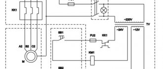
Here is a visual diagram of what should be connected to the main switch by conductors of the potential equalization system.
And now the main question is - what cross-section should the grounding bus be? What does it depend on, where to install it and how to connect it?
Grounding installation
Before you begin installing a grounding cable, you should check the existing system; to do this, you need to evaluate which cables are responsible for the “ground”.
- According to the existing requirements of clause 1.1.29, the PUE of the grounding cable has the Latin designation - PE.
- The colors of the ground wires should be yellow and green, although you can’t be sure of this, so it will be better if you ring them first.
Grounding in a three-wire wire is carried out only using those connection methods that can provide optimal contact, as well as a transition resistance close to zero.
This includes soldering, welding, tightening a nut-bolt connection using a tip, sleeve, or terminal.
If all the requirements of the PUE, the rules for choosing a cross-section, the methods of installing the grounding cable and the “earth” circuit are met, then no problems will arise and safety for humans will be fully guaranteed, and of course the operation of electrical installations and devices themselves.
A few words about the grounding device
It is recommended to ground all “dangerous” electrical appliances, the housing of which can be penetrated by a phase wire. Most often, these are electrical appliances that have a heating element in their design: a washing machine, an electric boiler, a water heater.
For your own needs, simple grounding in the form of one or three ground electrodes, which are spaced from each other at a distance of 1.5 meters in the shape of a triangle, is sufficient. Each of the grounding electrodes in this case is connected by a metal strip, preferably using welding, but it is also possible with bolts.
And further from the metal bus, the grounding wire enters the house. Accordingly, many people have a question about what wire is allowed to be used for these purposes and what cross-section it should be in order for the grounding to withstand the load.
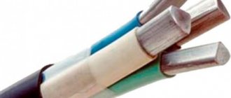
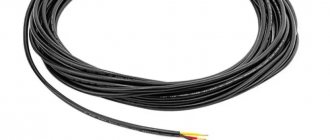
Photo of wire for grounding
Calculation of the cross-section of the grounding conductor
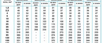
Many master electricians do not really delve into the essence of the issue and always purchase a cable with cores of the same cross-section. As a result, the “ground” wire does not differ from the phase or working “zero”. But the PUE provides for the smallest dimensions of grounding conductors and is listed in the form of formulas in a separate table.
Figure 2: Ground wires with pre-crimped terminal
Basic formulas for determining the smallest cross-section of a PE conductor:
- With phase cross-section S ≤ 16 mm2, cross-section of PE conductor: S.
- With phase cross-section 16 < S ≤ 35, cross-section of PE conductor: 16.
- With phase cross-section S > 35, cross-section of PE conductor: S/2.
It should be immediately clarified that such calculations are performed only at serious industrial enterprises, and when laying electrical wiring in scrap areas or apartments, they are very often neglected.
Brand and requirements for conductors
The core of a grounding wire or cable can be single-core or multi-core - it depends only on where it will be used. For example, to ground a door in an electrical panel, you need to ensure its mobility. The rigid core will break due to constant opening of the door and its bending. Therefore, the core must have an appropriate flexibility class that does not interfere with opening, for example 3 and higher.
At the same time, to connect, for example, the casing of an electric motor of a pumping station to a gas pump, there is no need to ensure mobility, since this type of electrical equipment is permanently mounted. Therefore, rigid conductors can be used.
The grounding conductor can be:
- isolated;
- non-insulated;
- is part of the cable;
- be a separate single-core wire;
- aluminum;
- copper.
This begs the question: which wire should I use to connect the ground?
Stores sell cable products with different numbers of cores: 2, 3, 4, 5. This is necessary for assembling certain circuits for connecting devices and connecting electrical equipment to networks with different numbers of phases.
To connect grounding in sockets and other electrical equipment of a single-phase network, it is convenient to use three-core cables, for example VVG 3x2.5. And for connecting three-phase equipment to the network and grounding, four-core cables are intended, for example AVVG 4x32. Moreover, in thick cables the grounding conductor usually has a cross-section smaller than that of the phase conductors. Let's give examples.
Cables:
- VVG – suitable for internal use. To install it outdoors, it must be placed in corrugated pipes or pipes. It is produced with different numbers of cores; there is a more detailed review of this cable on the website. For use in hot rooms it is better to use VVGng-ls. This cable is rigid and better suited for permanent installation.
- NYM is a foreign brand with characteristics similar to VVG. Hard.
- VBBShv - suitable for outdoor use and burial in a trench, often used to connect a private house to the network. Hard.
Wires:
- PVA is well suited for connecting power tools and extension cords, because it consists of multi-wire flexible conductors. Produced in two and three-wire versions.
- ShvVP - similar to the previous one, only it is not round, but flat.
- ESUY is a single-core soft copper wire.
To connect the ground wire to plumbing fixtures and other things in the bathtub, you can use single-core wires marked PV. The number after these letters indicates the flexibility class, where PV-1 is a rigid core, and PV-4 or PV-6 is a stranded flexible core.
Why is it impossible to determine phase and zero by wire color?
According to the requirements of the PUE, conductors have their own color marking.
It is not recommended to rely 100% on this method of determination. The cables may have been mixed up at the factory, so we recommend checking them. When doing the work yourself, you can mark the purpose of the wires, especially if they are colorless.
To do this, you need to purchase heat-shrinkable tubes or electrical tape of different colors. In accordance with the rules, it is allowed to do independent marking not along the entire length of the electrical wire, but only at the connection points. The tube or insulating tape must be secured to the corresponding conductor and write down which color belongs to which conductor.
Welding
Currently, GOST does not mention arc welding among the methods acceptable for connecting ground wires
There are two main types of welding - electric arc and exothermic. During electric arc welding, the temperature reaches +7000°C, which causes the destruction of the protective anti-corrosion layer. In addition, intense heat weakens not only the coatings, but also the metals from which the cores of the conductors are made. So-called intergranular corrosion occurs, which can potentially lead to destruction of the connection. That is why GOST R 50571.5.54-2013 does not include arc welding among the acceptable methods for connecting grounding conductors.
Set for exothermic conductor welding
Instead of arc welding, so-called exothermic (sometimes also called thermite) welding is now used to connect grounding wires. In exothermic welding, the so-called thermite, a powdered mixture of aluminum or magnesium with iron scale (or copper oxide), is used to heat the metal. For the ground loop, aluminum and copper oxide thermite are typically used. The joint is molded with refractory material, a powdered thermite composition is poured there, which is then set on fire. As a result of thermite combustion, liquid copper is formed, which has good adhesion to the materials being welded. The melt temperature exceeds 3000°C. Exothermic welding complies with the standards of both GOST R 50571.5.54-2013 and PUE.
You can see how exothermic welding is carried out in the video:
Ready-made kits for exothermic welding are available, the use of which does not require special training. However, other things being equal, the use of exothermic welding is still more complicated than connecting wires with screw terminals. Naturally, special requirements are imposed on screw terminals suitable for connecting ground wires.
Frequently asked typical questions from readers
- The electrical plug on the old Soviet water pump has been cut off. All wires are the same color. How to determine where the protective conductor is?
In principle, there is nothing complicated here; to determine the protective conductor you will need the pump itself and a multimeter (tester); if you have neither a multimeter nor a tester, but have a megohmmeter, then you can use that.To check, follow these steps:
— Strip the ends of the three conductors that come out of the pump in such a way that you can clearly touch them with the probe in turn, excluding contact of the probe with adjacent conductors.
— Then set the tester to continuity testing mode, connect the probes to the corresponding terminals of the multimeter.
— Fix one dipstick on the pump body. It is important that the installation location makes good contact, so if there is paint, a thick layer of dirt and other obstacles to the flow of electric current into the housing, they need to be cleaned or a different location chosen.
— Using the second probe, as shown in the figure below, touch each of the cores of the pump power cord one by one.
— The core that shows the circuit with the body is the protective conductor. Accordingly, the other two are the phase conductor and the neutral conductor.
This method is relevant for checking a working pump; if the insulation of the windings of an electrical machine has a breakdown to the housing, then not only the PE conductor will contact the ground.