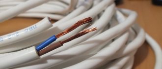
Using our calculator, you can calculate the cable cross-section by power (load) or current, taking into account the line length with a minimum error. The main indicators are the conductor material (copper, aluminum), voltage (220 V / 380 V) and load/current in the circuit. The method of laying the cable affects the cross-section of the conductor - closed cables require a larger cross-section, since due to limited heat transfer the metal heats up more. After carrying out the classic calculation for power/current, an additional calculation is carried out for the length of the conductor - the largest of the resulting pair of values is selected. The theoretical basis for the calculation is presented below in the form of formulas and tables. You may only be interested in the voltage loss calculator.
Related regulatory documents:
- PUE-7 “Rules for electrical installations”
- SP 76.13330.2016 “Electrical devices”
- GOST R 50571.5.52-2011/IEC 60364-5-52:2009 “Low-voltage electrical installations. Selection and installation of electrical equipment"
- GOST 31946-2012 “Self-supporting insulated and protected wires for overhead power lines”
- GOST 31947-2012 “Wires and cables for electrical installations for rated voltage up to 450/750 V”
- GOST 6323-79 “Wires with polyvinyl chloride insulation for electrical installations”
- GOST 31996-2012 “Power cables with plastic insulation for a rated voltage of 0.66; 1 and 3 kV"
- GOST 433-73 “Power cables with rubber insulation”
How to calculate cable cross-section by power?
First step . The total power of all electrical appliances that can be connected to the network is calculated:
Psum = (P1 + P2 + .. + Pn) × Kс
- P1, P2 .. – power of electrical appliances, W;
- Kc – demand coefficient (probability of simultaneous operation of all devices), default is 1.
Second step . Then the rated current in the circuit is determined:
I = Psum / (U × cos ϕ)
- Psum – total power of electrical appliances;
- U – network voltage;
- cos ϕ – power factor (characterizes power losses), default is 0.92.
Third step . At the last stage, tables are used in accordance with the PUE (Electrical Installation Rules).
Table of copper cable cross-section by current according to PUE-7
| Conductor cross-section, mm2 | Current, A, for wires laid | |||||
| open | in one pipe | |||||
| two single-core | three single-core | four single-core | one two-wire | one three-wire | ||
| 0.5 | 11 | — | — | — | — | — |
| 0.75 | 15 | — | — | — | — | — |
| 1 | 17 | 16 | 15 | 14 | 15 | 14 |
| 1.2 | 20 | 18 | 16 | 15 | 16 | 14.5 |
| 1.5 | 23 | 19 | 17 | 16 | 18 | 15 |
| 2 | 26 | 24 | 22 | 20 | 23 | 19 |
| 2.5 | 30 | 27 | 25 | 25 | 25 | 21 |
| 3 | 34 | 32 | 28 | 26 | 28 | 24 |
| 4 | 41 | 38 | 35 | 30 | 32 | 27 |
| 5 | 46 | 42 | 39 | 34 | 37 | 31 |
| 6 | 50 | 46 | 42 | 40 | 40 | 34 |
| 8 | 62 | 54 | 51 | 46 | 48 | 43 |
| 10 | 80 | 70 | 60 | 50 | 55 | 50 |
| 16 | 100 | 85 | 80 | 75 | 80 | 70 |
| 25 | 140 | 115 | 100 | 90 | 100 | 85 |
| 35 | 170 | 135 | 125 | 115 | 125 | 100 |
| 50 | 215 | 185 | 170 | 150 | 160 | 135 |
| 70 | 270 | 225 | 210 | 185 | 195 | 175 |
| 95 | 330 | 275 | 255 | 225 | 245 | 215 |
| 120 | 385 | 315 | 290 | 260 | 295 | 250 |
| 150 | 440 | 360 | 330 | — | — | — |
| 185 | 510 | — | — | — | — | — |
| 240 | 605 | — | — | — | — | — |
| 300 | 695 | — | — | — | — | — |
| 400 | 830 | — | — | — | — | — |
Table of cross-section of aluminum cable by current according to PUE-7
| Conductor cross-section, mm2 | Current, A, for wires laid | |||||
| open | in one pipe | |||||
| two single-core | three single-core | four single-core | one-two-core | one three-wire | ||
| 2 | 21 | 19 | 18 | 15 | 17 | 14 |
| 2.5 | 24 | 20 | 19 | 19 | 19 | 16 |
| 3 | 27 | 24 | 22 | 21 | 22 | 18 |
| 4 | 32 | 28 | 28 | 23 | 25 | 21 |
| 5 | 36 | 32 | 30 | 27 | 28 | 24 |
| 6 | 39 | 36 | 32 | 30 | 31 | 26 |
| 8 | 46 | 43 | 40 | 37 | 38 | 32 |
| 10 | 60 | 50 | 47 | 39 | 42 | 38 |
| 16 | 75 | 60 | 60 | 55 | 60 | 55 |
| 25 | 105 | 85 | 80 | 70 | 75 | 65 |
| 35 | 130 | 100 | 95 | 85 | 95 | 75 |
| 50 | 165 | 140 | 130 | 120 | 125 | 105 |
| 70 | 210 | 175 | 165 | 140 | 150 | 135 |
| 95 | 255 | 215 | 200 | 175 | 190 | 165 |
| 120 | 295 | 245 | 220 | 200 | 230 | 190 |
| 150 | 340 | 275 | 255 | — | — | — |
| 185 | 390 | — | — | — | — | — |
| 240 | 465 | — | — | — | — | — |
| 300 | 535 | — | — | — | — | — |
| 400 | 645 | — | — | — | — | — |
In the electrical installation rules of the 7th edition there are no tables of cable cross-section by power , there is only data on current strength. Therefore, when calculating sections using load tables on the Internet, you risk getting incorrect results.
Current calculation using additional parameters
When calculating the cross section based on current using the PUE table, you can also use additional parameters.
For example, it is possible to take into account the core diameter. Therefore, when determining the cross-section of the conductor, special equipment called a micrometer is used. Based on its data, the thickness of each core is determined. Then, using the values of previously obtained currents and a special table, the final selection of the cross-sectional value of the wire core is made.
If the cable consists of several cores, then you should measure one of them and calculate its cross-section. After this, to find the final thickness value, the indicator obtained for one core is multiplied by their number in the wire.
The value of the cable cross-section obtained in this way using calculations and the PUE table will allow you to create wiring in a house or apartment that will serve the owners for quite a long period of time without the occurrence of emergency or emergency situations.
Selecting cable cross-section based on current strength
First step . The calculation is carried out in exactly the same way, that is, first the total power of all electrical appliances that can be connected to the network is calculated:
Psum = (P1 + P2 + .. + Pn) × Kс
- P1, P2 .. – power of electrical appliances, W;
- Kc – demand coefficient (probability of simultaneous operation of all devices), default is 1.
Second step . Then the rated current in the circuit is determined (for direct and alternating current (1-phase/3-phase), respectively):
I = Psum / UI = Psum / (U × cos ϕ) I = Psum / (U × cos ϕ × √3)
- Psum – total power of electrical appliances;
- U – network voltage;
- cos ϕ – power factor (characterizes power losses), default is 0.95.
Third step . At the last stage, the same tables are used, according to the PUE (Electrical Installation Rules), which are located above.
Current Density
When choosing a wire cross-section, you need to know some indicators. So, for example, the current density in a material such as copper ranges from 6 to 10 A/mm2. This indicator is the result of many years of experience by specialists and is adopted based on the basic rules governing the design of electrical installations.
In the first case, with a density of six units, the electrical network is provided for long-term operation. If the indicator is ten units, then it should be understood that network operation is not possible for a long time during periodic short turns on.
Therefore, it is necessary to select the thickness precisely according to this permissible indicator.
The above data is for copper cable. Aluminum wires are still used in many electrical networks. At the same time, copper cable has its undeniable advantages in comparison with the latter type of wire.
These include the following:
- Copper cable has much greater softness and at the same time its strength is higher.
- Products made from copper are not subject to oxidation processes for a longer period of time.
- Perhaps the most important indicator of a copper cable is its higher degree of conductivity, and therefore a better indicator of current density and power.
The most important disadvantage of such a cable is its higher price.
The current density indicator for aluminum wire is in the range from four to six A/mm2. Therefore, it can be used in less critical structures. This type of wiring was also actively used in the last century in the construction of residential buildings.
Calculation of power consumption and current
Electrical power is calculated for each group separately. This indicator is estimated at the stage of developing a power supply project. For example, a standard kitchen requires up to three groups. We consider how many and what electrical appliances are planned to be connected to each line.
Power ratings can be found in technical descriptions or on the case. If for some reason this data is not available, then the average indicators for the main types of household appliances are listed in Table 2.
Table 2 power of household appliances and lighting table
| № | Name | Power | Notes |
| Lighting | |||
| 1. | Incandescent lamp | 60W/75W/100W | |
| 2. | Energy saving lamp | 7 W/9 W/11 W | |
| 3. | Spotlight (halogen lamps) | 10W/20W/35W/50W | |
| Electric stove | |||
| 1. | Independent hob | 6600 W | BOSCH - glass ceramics |
| 5800 W | ZANUSSI – 4 burners | ||
| 7000 W | ZANUSSI – 4 simple +2 inductor burners | ||
| 2. | Independent oven | 3000 W | AEG – 51 liter |
| 3500 W | ELECTROLUX – 50 liters | ||
| 3500 W | ARISTON – 56 liters | ||
| 3. | Dependent oven | 10800 W | ELECTROLUX – 9 modes |
| 10100 W | ZANUSSI | ||
| 4. | Built-in kit HANSA | ||
| Burners (2.2+1.2+1.2+1.8) kW | =6400 W | ||
| Oven | |||
| Bottom heating: | 1300 W | ||
| Top heat: | 900 W | ||
| Grill: | 2000 W | ||
| Convection: | 4 W | ||
| Lighting: | 25 W | ||
| Total max. power | 10629 W | ||
| 5. | Grills, barbecue grills, barbecue grills | 1300 W – 1700 W | |
| 6. | Hood | 240W-300W | |
| 7. | Food processors | 450 W, 750 W, 800 W | |
| 8. | Juicer | 25–30 W | |
| 9. | Microwave ovens without grill | 800-900 W | |
| 10. | Microwave ovens with grill | 2400 W | |
| 11. | Dishwasher | 2200 W | |
| 12. | Toasters, roasters | 850–950 W | |
| 13. | Mixers | 350–450 W | |
| 14. | Built-in steamers | 2200–2500 W | |
| 15. | Tabletop steamers | 850–950 W | |
| 16. | Air fryers | 1300 W | |
| 17. | Egg boiler | 400 W | |
| 18. | Washing machine | 2200 W | |
| 19. | Electric kettle | 2200–2400 W | |
| 20. | Fridge | ||
| Energy class "A" | 160 W | AEG – 280 liters | |
| 90 W | BOSCH – 279 liters | ||
| 21. | Freezer | 100–120 W |
The maximum possible values should be selected and taken into account when choosing wiring, as well as the dependence of the cable cross-section on the load (Table 1). The total power is the sum of each individual power P=P1+P2+P3+…Pn.
The current strength is calculated using the formulas:
- for single-phase network I=P/220
- for three-phase network I=P/(√3×380)
When calculating the electric current and the cross-section of the input cable wires, the total power consumption is multiplied by a factor of 1.5 to provide some reserve. If it is laid hidden, the thickness of the cores increases by one and a half times.
About choosing a cable brand for home wiring
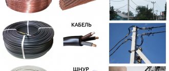
Making apartment electrical wiring from aluminum wires at first glance seems cheaper, but operating costs due to low reliability of contacts over time will be many times higher than the costs of electrical wiring made from copper. I recommend making the wiring exclusively from copper wires! Aluminum wires are indispensable when laying overhead electrical wiring, as they are light and cheap and, when properly connected, serve reliably for a long time.
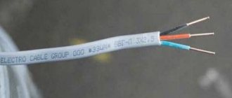
Which wire is better to use when installing electrical wiring, single-core or stranded? From the point of view of the ability to conduct current per unit of cross-section and installation, single-core is better. So for home wiring you only need to use solid wire. Stranded allows multiple bends, and the thinner the conductors in it, the more flexible and durable it is. Therefore, stranded wire is used to connect non-stationary electrical appliances to the electrical network, such as an electric hair dryer, an electric razor, an electric iron and all the others.
After deciding on the cross-section of the wire, the question arises about the brand of cable for electrical wiring. The choice here is not great and is represented by only a few brands of cables: PUNP, VVGng and NYM.
PUNP cable since 1990, in accordance with the decision of Glavgosenergonadzor “On the ban on the use of wires such as APVN, PPBN, PEN, PUNP, etc., produced according to TU 16-505. 610-74 instead of APV, APPV, PV and PPV wires according to GOST 6323-79*" is prohibited for use.
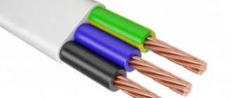
Cable VVG and VVGng - copper wires in double polyvinyl chloride insulation, flat shape. Designed for operation at ambient temperatures from −50°С to +50°С, for wiring inside buildings, outdoors, in the ground when laid in tubes. Service life up to 30 years. The letters “ng” in the brand designation indicate the non-flammability of the wire insulation. Two-, three- and four-core wires are available with core cross-sections from 1.5 to 35.0 mm2. If in the cable designation there is a letter A (AVVG) before VVG, then the conductors in the wire are aluminum.
The NYM cable (its Russian analogue is the VVG cable), with copper cores, round in shape, with non-flammable insulation, complies with the German standard VDE 0250. Technical characteristics and scope of application are almost the same as the VVG cable. Two-, three- and four-core wires are available with core cross-sections from 1.5 to 4.0 mm2.
As you can see, the choice for laying electrical wiring is not large and is determined depending on what shape the cable is more suitable for installation, round or flat. A round-shaped cable is more convenient to lay through walls, especially if the connection is made from the street into the room. You will need to drill a hole slightly larger than the diameter of the cable, and with a larger wall thickness this becomes relevant. For internal wiring, it is more convenient to use a VVG flat cable.
When laying apartment electrical wiring, as a rule, the question arises about choosing a circuit breaker, or, as it is often called, a machine. This issue and the choice of a meter, RCD, and differential circuit breaker are covered in detail in the website article “About the electric meter, RCD and circuit breakers.”
Open and closed wiring
As we all know, when current passes through a conductor, it heats up. The higher the current, the more heat generated. But, when the same current passes through conductors with different cross-sections, the amount of heat generated changes: the smaller the cross-section, the more heat is released.
In this regard, when the conductors are laid open, its cross-section may be smaller - it cools down faster, since heat is transferred to the air. In this case, the conductor cools down faster and the insulation does not deteriorate. When the gasket is closed, the situation is worse - heat is removed more slowly. Therefore, for closed installations - in cable ducts, pipes, in the wall - it is recommended to take a cable with a larger cross-section.
The choice of cable cross-section, taking into account the type of installation, can also be made using the table. The principle was described before, nothing changes. There's just one more factor to consider.
Selection of cable cross-section depending on power and type of installation
And finally, some practical advice. When going to the market to buy a cable, take a caliper with you. Too often the stated cross-section does not coincide with reality. The difference can be 30-40%, which is a lot. What does this mean for you? Burnout of wiring with all the ensuing consequences. Therefore, it is better to check right on the spot whether a given cable actually has the required core cross-section (the diameters and corresponding cable cross-sections are in the table above). more about determining the cable cross-section by its diameter here .
