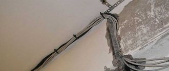
Overhead power lines have been familiar to us since early childhood and their presence next to us is taken for granted, as a sign of “civilization” and the availability of comfort. Like any man-made element, the technical genius of man, these power lines have their own weak points and strength limits. One of the common phenomena is sagging of the wire, caused by the destruction of the insulator, weakening of the bandage, or the presence of a foreign object on the supporting conductors (for example, a fallen tree or branches). In addition, power lines sag due to external force majeure factors, as well as deterioration of funds. In this article we will tell readers of the site for electricians how to tension the wire from the pole to the house when it is sagging, as well as when connecting the area to electricity.
Scope of technology
Such technologies are used only in electrical networks with a voltage not exceeding 1000 volts, the requirement of the PUE is Chapter 2.1. In most cases, the laying of cables on cables is used from buildings or power lines to individual structures over short distances. Where installation of power transmission line supports or digging trenches for cables is impossible due to technical production conditions during the operation of facilities, or unreasonably due to the volume of work performed, it is expensive from a financial point of view.
In production workshops, warehouses, buildings with large areas, high ceilings, the best option for lighting is to use these technologies. Cable cables are used for electrical networks of street lighting in certain areas.
For private home owners, this wiring method eliminates the time-consuming work of digging a trench. It’s easier to stretch a cable through the air from the distribution board in the house to outbuildings:
- workshop;
- summer kitchen;
- gazebo with barbecue;
- chicken coop;
- bathhouse and other possible structures in the courtyard of a private household.
Cable wiring allows you to conduct light three-wire wires for electrical consumers of low power and cables with large cross-section wires for power supply of powerful household appliances. Before proceeding with the installation of cable wiring, preliminary calculations are required.
Advantages of using SIP when connecting a house from a support
Today, entry into a private house is carried out exclusively with SIP wire. Cost savings and high advantages of SIP over conventional bare wires make its use the most popular.
- The special design and thoughtful suspension scheme makes both installation and fittings much more economical than using non-insulated lines;
- even if the wires overlap, the occurrence of a short circuit will tend to a minimum;
- The reinforcement has high tensile strength. This allows you to maintain the integrity of the wire when external loads occur - contact with fallen tree branches, unsuccessful vehicle passage, or insufficiently careful operation of the PMG;
- there is the possibility of installation using the walls of buildings;
- working under voltage with self-supporting insulated wires reduces injuries.
Designation on the SIP wire:
- C - means self-supporting wire
- And - talks about insulation around current-carrying conductors
- P - indicates that this is a wire
SIP wire has five main versions. Differences in the load-bearing core and in the number of insulated cores.
Unaccounted for connections, which were previously made using a simple throw-on method, are significantly reduced. The operating costs of the system are significantly reduced, since hanging the wire on supports is a very simple and reliable system.
Preliminary measures before installation
At the first stage, it is necessary to determine how much power will be consumed by electrical appliances in the structures that are planned to be provided with electricity. Based on the power consumption, the cross-section of the cable wires is calculated, its length and weight are taken into account. These parameters determine which fasteners to use, the diameter and material of the cable. To calculate power consumption and cable cross-section, a more detailed study of a separate topic is required. In simplified form it looks like this:
- The power of all electrical appliances that are supposed to be used in the calculated network is summed up. The power of each device is indicated in product passports or nameplates on the housing. The simplest example of a lighting lamp is always written 40 on them; 60; 75 or 100 or more watts.
∑Р = P1 + P2 +…Pn = 3.7 kW. (3700 W) – Total power.
- Determine the maximum possible current in the circuit
I = ∑Р/ U=3700 W/220 V = 16.8 A. – Maximum current.
U – network voltage.
- To determine the cross-section of wires in a cable, use the table
In our case, we choose a maximum current value slightly greater than 19A, taking into account that additional household appliances may be used in the future. According to the table, we obtain a power of 4.1 kW, which corresponds to a copper wire cross-section of 1.5 mm. You need to understand that the cross section is not the diameter, it is calculated using the formula:
Formula for calculating wire cross-section
Experienced electricians are well aware of the standards of cables and wires and determine the cross-section by eye. For ordinary consumers, there are tables for determining the cross-section by diameter ; it is enough to measure the diameter of the wire with a micrometer or caliper and determine its cross-section using the table.
Determining wire cross-section by diameter
- The next stage of preliminary work is measuring the length of the cable from the distribution board in the house to the switchgear (switchgear) on the building to which the cable structure is stretched. This can be done with a regular tape measure,
Tip #1. Be sure to take into account the cable reserve for cutting and connecting to the control panel; add approximately 30 cm at both ends.
The first nine-story building in Russia
Since the Soviet government was looking for a way to provide all citizens with separate and inexpensive housing, they gradually introduced multi-story buildings into operation. But, as it turned out, the first nine-story building appeared only in the early 1960s.
Of course, it seems that a lot of time has passed and the service life of such structures is approaching the end, but for our grandparents, high-rise buildings have become a real salvation. After all, they were able to move from communal apartments to separate apartments.
Nowadays many interesting residential buildings are appearing, but the past does not let us forget about itself. There will always be new information that can excite our imagination and once again make us think about how many fundamental techniques were developed by USSR engineers.
Selecting the diameter and material of the cable
Determine the weight of the cable and other elements that will be attached to it. If the distance between the supporting fasteners is 5-6 m and the weight of the wire is not significant, you can stretch galvanized steel wire with a diameter of 2-3 mm. When the distance is more than 10 m, the cable is heavy, especially if the cable structure is used with lighting elements, galvanized steel cable with Ø 4-6.5 mm is used. Such a cable will withstand any cable with a wire cross-section of up to 10 mm/sq.m; larger cables are not used in private households due to limited power consumption. You can also hang up to 5 pieces on such a cable. lighting lanterns in a lightweight housing.
The cable can be wound and weighed on ordinary scales, or calculated by knowing its brand according to the characteristics table, which is included with the sale. The weight of the cable per 1 meter is indicated; you need to multiply the specified weight by the number of meters to get the total weight of the segment that is used for fastening to the steel cable.
For domestic conditions, in order not to waste money, you can hang the cable that was used for hidden wiring. In order for the insulation to last longer, lay it in a corrugated pipe; its weight is not significant. There are reference tables indicating the brand and weight of the cable. You can look it up on the Internet; some sites have calculators for calculating the length and weight of wires and cables.
Table indicating the cable brand and weight in kg. by 1 meter
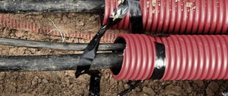
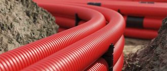
For high current loads, it is better to use special cables for overhead cable structures:
- AVT, AVTS, APT already have a built-in supporting steel cable;
- AVRG, ANRG, APVG, AVVG are suspended from a supporting steel cable.
Connecting and setting up a local network between two houses
So, the cable is tightened, routers or PCs are installed on both sides of the cable, all we have to do is crimp the cable and insert the connectors into the LAN connectors.
We will not dwell on how to crimp a cable, since there is plenty of this information. Let us only recall the order of the wires in the connector. It should be the same on both sides.
We connect connectors to the network interfaces of computers or, if it is necessary to expand the network to more devices, a network switch.
We register IP addresses from the same subnet on the network interfaces.
Ready.
Advantages of the method:
The cable is not expensive, everything is installed quite quickly. Bandwidth 100 Mbit/s (useful traffic can be received up to 60 – 70 Mbit/s)
Disadvantages of this method:
Over time, the cable loses its insulation strength and becomes unusable.
For long distances at altitude, it serves as an accumulator of static electricity and, especially during a thunderstorm, can easily damage network equipment. If the cable is connected directly to the computer, the entire motherboard and power supply may be damaged.
You can, of course, use lightning protection:
but it must be grounded without fail, otherwise it will be of no use.
Supporting and tensioning elements of cable wiring
These products are installed on the walls of buildings, structures between which tension is stretched. Depending on the material and diameter of the cable, the fastening design is selected:
- Tension bolt, hook and tension anchor are used for flexible multi-core industrial cables carrying heavy loads; rolled wire with a diameter of up to 6 mm can be used.
- Anchors for tensioning strings with a small diameter are designed for light wires with a cross-section of up to 6 mm at a distance of up to 10 meters, without lighting elements.
- Anchors for industrial cables and wire rods are capable of supporting heavy cables and lighting elements at a distance of up to 12 m without additional supports.
- Fasteners for stringing parallel lines are often used for dual purposes, for power supply to structures and placement of lighting lanterns. A power cable with a wire cross-section of 10 -35 mm/sq. is laid along one cable; on the second, lighting outlets and distribution boxes with copper wire 2.5 - 4 mm are laid.
Types of end fastening elements
All these structures have individual characteristics when installed on the walls of buildings.
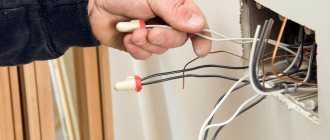
Entering the cable into the house from a pole. Connecting SIP wires to the house
Modern installation of SIP cable from pole to house is free of these problems. SIP insulation consists of cross-linked polyethylene, which is not susceptible to atmospheric influences. Sudden temperature changes also do not affect its insulating properties. Thanks to high-quality insulation, short circuits during overlaps are excluded. Such an input can faithfully last up to 25 years!
Material
The brands of materials from the manufacturer ENSTO are indicated here; in your case, the specification (SLIP, SO, SOT, etc.) may not be the same, but the names themselves (piercing clamp, anchor clamp, clamp) should be the same.
Before starting work, it will be necessary to take certain measurements. The distance from the support to the facade of the house where the wall hook will be located should be no more than 25 m. Otherwise, you will have to install an additional support support.
Choose SIP depending on what input you will be installing into the house - 220V or 380V. When purchasing SIP, it is better to make some reserve in footage for all sorts of unforeseen situations. Basically, the 4*16 SIP brand is used for entering the house.
If the main overhead line to your house is made of bare, uninsulated wires, then the clamps must be appropriate. One side for contacts has a smooth surface, the other has teeth. When there is also an SIP hanging on the main power line, in this case, choose clamps with piercing teeth on both sides of the contact substrate.
Two hooks are installed on the support and facade of the house. It is between them that the SIP is stretched. Its fixation is carried out with anchor tension clamps.
Installation of inlet inside the house
All the main questions and disputes about how to properly install a SIP cable from a pole to a house arise when it comes to the entry of power supply into the house. Some people believe that the input should be solid and there is no need to make an additional connection, and in some ways they are right. But here we can make one recommendation.
If you purchased a simple SIP not of the NG brand (non-flammable), then make the connection inside the house with a VVgNg copper cable.
How SIP supports combustion can be seen in this video:
The cable itself must be led through the wall into the house in a plastic or metal pipe.
What else is worth paying attention to when installing SIP:
Distance from power lines to a residential building: safe and acceptable minimum SanPiN norm, harm to health
You can also use special hand winches to tighten the cable wiring. During tensioning, the wire must be additionally fixed using anchors. In the video below you can see how to stretch the wire from the pole to the house.
Expert opinion
It-Technology, Electrical power and electronics specialist
Ask questions to the “Specialist for modernization of energy generation systems”
How to tighten a sagging wire: troubleshooting method, permissible sagging It is problematic to carry out notification today, since you need to report the sagging wire to the relevant authorities. Ask, I'm in touch!
Requirements for installation of end fastenings and installation features
Never attach end pieces to decorative building siding or roofing components. Devices intended for heavy loads are fixed on both sides of the load-bearing wall with steel plates fastened with through bolts. As shown in the picture for the tension bolt with hook. They must be located above pedestrian passages at a height of at least 2.7 m, and above vehicle passages at least 6 m. Anchors for strings with lighter loads can be secured with simple anchor screws for concrete.
Ideally, tension anchor devices are installed in the wall during the construction of buildings according to the project. In practice, this is not always provided for; then you have to drill into the walls with a hammer drill. Under the end fastening, a metal plate with a bolted contact is attached at 20-30 cm for grounding the cable. It is connected by a welding joint to rolled wire with a cross-section of at least 16 sq/mm, which goes to the common ground loop. In some cases, grounding is performed with a separate copper wire with a cross-section of at least 2.5 sq/mm using bolted connections.
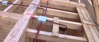
Laying the cable on a cable when connecting to a wall
| Option A - direct connection of the cable to the ground terminal | Option B – grounding the cable with a separate wire. |
| 1 – tension anchor; 2 – loop with a cylindrical clamp; 3 – wire rod going to the ground loop; 4 – grounded end of the cable; 5 – bolted grounding contact. | 1 – tension anchor; 2 – loop with clamping plates on bolts; 3 – wire going to the ground loop; 4 – bolted connection of the copper grounding wire with the cable; 5 – stranded copper wire with a cross-section of 2.5 sq/mm or more; 6 – bolted connection of the wire to the ground loop. |
Rules and regulations
The main condition for the trouble-free existence of buildings on a land plot is compliance with all the necessary rules and regulations provided for by existing legislation. SNiP 30-02-97 as amended for 2022 and SP 53.13330.2011 are now being considered at the legislative level.
Power lines near the city
A safe distance from power lines can be determined even independently, although when obtaining permits, officials approving the construction project must indicate the inadmissibility of being close to power lines. According to existing rules, the minimum safe distance from the supporting electrical wire of a structure is determined as follows:
- 35 kV, on a pole - 3-4 insulators - 10 meters;
- 110 kV – 6–8 insulators – at least 20 meters;
- 220 kV – 15 insulators – from 20 to 25 meters;
- 330 kV – 2 wires in a bundle on one phase of a power line column – required distance – 20–25 m;
- 500 kV – 3 wires on one phase – distance requirements – 30 meters;
- 750 kV – 4 wires in phase – 40 meters;
- 1150 kV – 55 m minimum recommended distance, although you can find recommendations to add another 5–10 m.
Power line
Calculating the distance from the fence to the power line support is fundamentally incorrect. According to the rules, such a distance is defined as a perpendicular drawn to the fence post from the extreme line of wires. The minimum height for a power transmission line is considered to be 7 m, which means that under unfavorable conditions, the charge accumulated by it can be discharged into the atmosphere, causing destruction and irreversible consequences. Therefore, for greater safety, it is not the distance from the support that is considered. The required meters must be measured from the outermost point of the wire located on the side of the fence.
Installation and tension of the cable
After installing the terminal fastenings, the cable is attached to the guy wire on the ground, lighting fixtures with junction boxes are fixed and connected. The assembled structure is delivered to the installation site and unwound along its entire length from one mounting anchor to another.
The length of the cable must be at least 2 m greater than the distance between the end anchors. The reserve will be needed to seal the fastening to the terminal devices and bring the ends to the grounding terminals, which are located below the anchors. The end loops of the cable are attached to the tension anchors, after which they regulate the tension. The tensile force should be up to 100 kg/cm for light structures with cables with a cross-section of 4-10 sq./mm. For heavy cables with a cross-section of 16 – 25 sq./mm – up to 500 kg./cm. This parameter is measured by a dynamometer, which is installed between the anchor and the tension loop.
After tensioning the cable, the ends of the cable are grounded, the cable is inserted into distribution devices and connected to protective circuit breakers.
Local network between buildings via wi-fi
(distance approximately 500 m, using external antennas – 1 – 2 km)
The first condition for using this method is direct visibility between the transmitting and receiving devices and the absence of any structures on the transmitter-receiver line. This option is very suitable when the houses are located one against the other and the windows of one house “look” into the windows of another house. It is desirable that it be floor 5 or higher, which will prevent the appearance of objects blocking the radio link.
So, if the distance between the windows of the houses is up to 400-500m and they are approximately at the same level (plus or minus 3 floors) - you will only need two access points, preferably with removable antennas. For example, let's take the TP-LINK TL-WA701ND equipment
Connect according to the manufacturer's instructions
We configure one of the access points in AccessPoint mode, and the other in Client mode.
Elements for fastening the cable to the cable
To securely fix the cable with the cable, there are several devices:
The simplest method is twisting the cable with stretching using ordinary aluminum wire Ø 2.5 - 5 mm with insulation. At connections every 50 -80 cm, 7-8 turns of wire are made, tightly turn to turn. To prevent the cable insulation from being pressed through by the fastening wires, the fastening point is wrapped with a rubber plate, and the wire is wound on top. It is recommended to use rubber for gaskets from old car inner tubes;
Plastic tie for securing the cable. The device is attached to a guy wire, the cable is laid in a groove, covered with a strap, which is threaded into the lock, tightened and securely fixed. The lock is designed in such a way that the strap cannot be pulled out in the opposite direction; to remove it, you can only cut it.
Plastic tie for securing the cable.
Metal clamping plates with loops for cables and guy wires. Plates are produced with loops of different sizes. One plate is put on the cable and the other on the cable. In the center of the plates there is a hole with a thread for a bolt; they are aligned and tightened with a bolt.
Metal clamping plates with loops for cable and guy wires
All connections, regardless of the design, are installed after 50 - 80 cm.
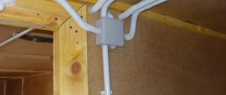
Distribution boxes and lighting devices for cable mounting
To fasten distribution boxes, special galvanized iron plates with cut-out shapes are used. A part of the plate is bent from the cut-out shape, a cable and a box are inserted, after which everything is fixed with bent elements.
An example of attaching a junction box to a cable
To fasten lighting fixtures, galvanized plates of a special shape are used, but the principle of fastening remains the same, shown in the figure.
- Cable;
- Plate;
- Cable;
- Junction box;
- Lampshade with lamp socket.
How to increase the range of a wifi network connection between two houses?
It may seem funny, but so-called “can reflectors” can increase communication range and stability
The access point's circular antenna turns into a highly directional one.
The reflector presented below, placed on only one of the router’s three antennas, amplified the signal received by the phone from -62 dBm to -51 dBm.
For the test, we used a Xiaomi Redmi 4 Prime phone with the WiFiAnalyzer application installed. Signal reception from a distance of 30 - 35 m (through a window onto the street).
Using factory-made external antennas with increased gain, the coverage area increases significantly and can reach several kilometers.
Advantages of the method:
Easy to install. In fact, you need to take it out of the box, connect it and make a few clicks. Mobility of installation - when moving, everything can be easily packed into a suitcase and used in another place.
Disadvantages of this method:
Sensitivity to interference, especially when installing more powerful antennas. The equipment is more expensive than copper cable. Suitable only in case of direct visibility between access points. Bandwidth depends on signal strength.