DC brushed motors are used in drives that require smooth speed control over a wide range. It is important to ensure the safe start-up of the electrical machine. For this purpose, the voltage or resistance parameters of the motor rotor circuits are changed.
Electric drives with DC mains power are used as generators or motors. The most widespread are electric motors capable of operating with loads of up to several thousand kilowatts. This type of electrical equipment includes collector, valve and universal drives. Each of them has its own design and technical features that determine their use. The commutator electric motor: its structure, principle of operation and start-up mode will be discussed in this article.
Main structural elements
A commutator electric machine is equipment in which the shaft angular position sensor and the current load switch in electrical circuits are the same device, called a brush-commutator unit. The general structural diagram of any commutator motor (CM) is similar to other types of electric motors. The stationary part is called the stator/inductor/inductor wheel, the moving/rotating part is called the rotor/armature. The drive structure is shown in the figure:
The stator contains a frame (supporting part) and main poles. The support structure serves to fix the poles and shields of the ball bearings. It serves as a component of the magnetic circuit, since it is the link through which the magnetic flux of the drive equipment is closed. The supporting part is made of metal, is extremely durable and magnetically permeable. It has supports in the lower part and special holes around the circumference for securing the cores of the main poles. As a rule, this is a solid element. A detachable design is available for variants with large dimensions. This makes transportation, assembly, maintenance and repair easier.
The main poles that generate the magnetic flux contain a core and a pole coil with a wound wire. On the side of the rotor assembly, the core has a special tip that distributes magnetic induction in the internal space of the CD. The cores are made of sheet steel. In low-power 220V electric motors, frameless poles are formed, with direct winding of the electrical conductor onto a pre-insulated core. In electric machines with a power of more than one kilowatt, the coil is a frame with a wire wound on it.
The structural diagram of the anchor mechanism includes the following elements:
- shaft;
- core with electric winding;
- collector node.
The core is made in the form of a laminated product, assembled from steel plates insulated with varnish, which are collected in a single package, baked and pressed onto the shaft. This solution makes it possible to reduce eddy current flows formed during rotation in magnetic space. A winding made of copper wire is placed in the outer grooves of the anchor assembly.
The collector device is one of the key and complex structural units of the compressor. Consists of copper trapezoidal plates assembled into a cylindrical shape. Depending on the method of fastening the metal elements, the collectors can be with steel cone-shaped washers or on plastic (for low-power electric machines). To ensure electrical contact with the commutator unit, brushes with a flexible cable are placed in special brush holders, which connects the brushes to the electrical circuit. For stable operation of the electric drive, constant reliable contact is ensured between the brush element and the commutator.
Useful tips
- A circuit assembled with your own hands must be checked several times to ensure that the parts match and the order in which they are connected. A small mistake can lead to unpleasant consequences. Electricity is no joke.
- But even after careful repeated testing, it is not recommended to install the device on an electric motor. Better to test. How? To do this, you will need three 60-100 watt incandescent light bulbs connected in series. We need to achieve the result so that all the lamps burn equally brightly.
- Pay attention to the capacity of the installed capacitors. It is very important here that the time they are turned on does not make a big difference. Acceptable value is up to 10%.
- The switching-off time of the capacitors can be adjusted with resistors (R). True, this alignment option can be used if the difference in off/on time is at least 30%.
And only after these manipulations can you connect the device to the electric motor.
Expert opinion
It-Technology, Electrical power and electronics specialist
Ask questions to the “Specialist for modernization of energy generation systems”
Soft Start of a 380 Volt Electric Motor with Your Own Hands Direct start | ✨World of light at the moment the electric motor starts, the supply current can exceed the rated one by four and a half to five times, which leads to significant heating of the windings, and this is not very good;. Ask, I'm in touch!
Operating principle
The operation of the commutator motor is ensured by a brush-commutator unit (BCU). This is the connecting link between the rotor electrical circuit and the external power supply network. In fact, the control panel performs the functions of a mechanical converter of alternating current value into direct current and vice versa. Despite the fact that CDs are DC devices, their operation requires the presence of an alternating current value in the rotor electrical circuit. Being the main functional part of the motor, the control panel significantly complicates its design compared to brushless drives. Accordingly, these types of motors are inferior in reliability and require higher manufacturing costs.
The conversion provided by the control panel is necessary to ensure that alternating current flows in the armature winding. Only in this case does a continuous process of electromechanical energy conversion occur. Voltage from a direct current source is supplied to the drive brushes. As a result of its contact with the magnetic field of the stator, electromagnetic forces (EMF) Fem
, creating an electromagnetic moment
M
. As a result, the anchor begins to rotate. After turning it 180 degrees, the EMC will not change its direction. This is due to the fact that simultaneously with the transition of each conductor of the rotor winding from the region of one magnetic pole to the region of another, the direction of the current flow in the conductors changes.
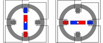
The internal interaction diagram of all elements of the control panel is presented in the form of a simplified model:
In the geometric neutral zone nn' - the middle of the interpolar region - magnetic induction and, accordingly, EMC are equal to zero. But with an increase in the number of conductors in the rotor winding, namely with their uniform distribution, and an increase in the number of collector plates, the torque becomes stable and uniform.
Assembling the motor control circuit
If necessary, you can continue the experiment and assemble a circuit to control a 3-phase motor with direct drive to the wheel.
For this:
- From the existing power steering unit of a car powered by a 3-phase motor, it is necessary to remove the unit with power transistors.
It will no longer be possible to use it as a full-fledged motor control module (BLDC).
- Next, the block of power transistors is connected to the 2CAN element via a homemade board equipped with transistor control drivers.
It can be done in a simple and quick way - using laser printing and an iron. The general connection diagram is shown in Figure 8.
Source we.easyelectronics.ru
Since not all pins of this element and the microcontroller are routed on the 2CAN board, you need to add more connections using surface mounting. The result is the design shown in the figure.
Duty cycle and its characteristics
The full operating cycle of any electric drive can be divided into four technological stages:
- start, during which the shaft/armature rotation speed increases from zero to the required value;
- working, during which the motor operates at a constant voltage at the terminals of the rotor circuit and the excitation circuit;
- regulation when the internal circuits (anchor block or excitation) are influenced in order to change the shaft speed;
- stop, characterized by a decrease in speed to zero.
According to the given cycle structure, starting, operating, control and braking characteristics are distinguished. The starting stage is considered in relation to the parameters of starting torque, current, process duration, cost of additional devices and energy costs. At the same time, they ensure the smoothest possible start of the commutator motor. The main characteristics of the mechanical energy of an electric motor are torque and rotation speed.
The operating period is estimated by a set of dependencies, including the shaft speed, current parameters of the drive in the rotor electrical circuit, useful torque, efficiency of the useful power of the CD at a constant supply voltage and current in the excitation winding. Regulatory characteristics are determined by the limits, steps and method of changing speed parameters. The ability to smoothly regulate the speed of an electric machine over a wide range is one of the most valuable qualities of this category of electrical equipment. The braking mode of the rotor mechanism when the power is turned off occurs due to friction forces. To speed up the stopping of powerful electric machines, one of the braking methods is implemented by creating a braking torque directed against the rotation of the armature.
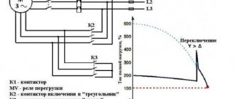
The similarity of thyristor starting with classical methods of starting electric motors
The thyristor starting method is similar to reduced voltage starting, which in earlier times was implemented as star-delta switching or step starting from an autotransformer. Thanks to thyristors, this starting method does not have the stepwise disadvantages of the last two methods, but, from the point of view of mechanical characteristics, it cannot shift the “hump” of the maximum torque region to the zero speed region, and is forced to put up with a drop in the starting torque when the current is limited.
Thyristor starting is not similar to starting a motor with a wound rotor, much less a DC motor with a series-connected field winding (see above). In most real situations, when we are upgrading an existing mechanism with an existing motor (asynchronous with a squirrel-cage rotor and star-connected windings), there are conditionally only 3 practical ways to “soften” the start:
- Autotransformer - in practice, the author is not aware of cases of application either in the Soviet era or at present.
- The actual soft start device ( SPD ), which, unlike the first method, allows you to flexibly adjust the starting conditions on a specific mechanism to suit its unique conditions.
- Frequency drive (converter) . By reducing the starting frequency to a few hertz, we, being also constrained by the “humpbacked” characteristic of the dependence of torque on slip, can reduce the starting current consumed from the power supply to values no higher than the rated value, even when starting under load. Details of the starting (and not only starting) properties of frequency converters are the topic of a separate article.
Start and its characteristics
The properties of electric drives are determined by all four groups of characteristics listed above: starting, operating, mechanical and adjusting. Starters determine the operation of the electric drive from switching on to the transition to the steady state of operation. When starting a commutator motor, the following conditions must be met:
- the starting moment of the thruster must be greater than the moment value of the static load; if they are equal, acceleration stops;
- the maximum current load and torque value at the start must be within the range of permissible limits.
In accordance with the operating conditions of the brush contact, the permissible current value is 2.5 IN for drives with power up to 5 kW and 1.5-2.0 IN for more powerful electric motors. According to the limitations of the supply network or the acceleration of the mechanism, the permissible current and torque values can be further reduced. But an excessively small value of the starting values is also undesirable due to a decrease in the initial torque and a delay in the acceleration process.
Any start-up begins with a short circuit mode, in which the rotor winding is connected to the network, and the shaft itself is stationary. That is, the electromotive force is zero. In this case, the current indicator of the armature mechanism circuit is determined in accordance with Ohm’s law:
Ikz = U/ra
Since the armature electrical resistance is very small in the natural characteristic, the magnitude of the starting current load is equal to: Is = (10–15) IN. In some cases, it can exceed the nominal value by forty times. Such a load is dangerous for the electric motor, as it can cause a “circular fire” on the commutator and develop an excessively large starting torque, which has an impact on the rotating parts of the mechanism. In addition to this Ikz
causes a sharp drop in network voltage, which negatively affects other network consumers.
From the above equation it follows that a soft start of a commutator motor is carried out either by reducing the voltage on the armature winding or by increasing the electrical resistance. When using mains power, a starting resistance is used. To do this, an external electrical resistance Rpr
in the form of a resistor, which is expressed by the formula:
Ikz = U/(Rpr + ∑r).
Rpr parameters
selected in such a way that
Is
does not exceed the permissible current values.
The selected electrical resistance satisfies the initial start-up conditions only. As soon as the rotor begins to rotate, an EMF is induced in its electrical circuits, limiting the current parameter of the rotor. At the same time, this causes a decrease in the initial moment. Therefore, measures are taken to reduce Rpr
by turning on a variable resistance resistor, called a starting rheostat. The rheostat has step adjustment and allows you to change this characteristic from maximum to minimum value.
Starting electric drives with a power of 0.7-1.0 kW, provided they are turned on without load, is carried out by direct connection to the network. A rheostat-free start for low-power electrical equipment does not pose a danger. This is explained by the relatively low starting current, which, due to the increased electrical resistance of the rotor winding and small rotating masses, exceeds the nominal parameter by three to five times. In addition, the acceleration time of this type of motor is also short and the effect of Isk
for a short time.
The second starting method - voltage regulation - is used only if there is an individual source of electricity that allows regulation of the voltage supplied to the drive. An example would be a converter-motor system. This method is used for electric motors of medium and high power.
How to convert a car generator into an electric motor
Typically, a generator is not capable of operating as a motor if voltage is applied to it. However, it has one important advantage - it creates practically no resistance to rotation if no current is supplied to it.
To turn it into a small-sized but quite powerful motor, it will have to be modified. Sequencing:
1. Carefully remove the plastic outer casing from the back of the generator.
Source sdelaysam-svoimirukami.ru
A 3-phase bridge of rectifying diodes is placed under it; it is fixed to the radiator. There is also a brush assembly equipped with a controller that regulates the output voltage.
2. The radiator is unscrewed along with the diodes.
Source sdelaysam-svoimirukami.ru
For the 95 Ampere generator model, the controller and brushes have one common housing made of plastic. This is where wire cutters may be needed to speed up the removal process.
3. It is necessary to saw off the brushes from the controller.
Source sdelaysam-svoimirukami.ru
The generator is made like a commutator motor. Equipped with 6 leads from 3 windings on the stator.
4. To turn on the triangle winding, you need to connect them all in series with each other.
Source sdelaysam-svoimirukami.ru
The diode bridge is removed from the generator, as well as the voltage regulator circuit.
5. After this, all elements are installed in their places.
Everything is carefully assembled in the reverse order. The generator began to look like in Figure 5.
Source we.easyelectronics.ru
The clip that sticks out of its back cover is a retainer for the spring-loaded brushes located in the recess. This makes it easier to install the back cover. Nothing breaks.
6. At the end of the assembly procedure, the paperclip is simply pulled out.
The brushes are firmly fixed in the desired position and rest against the commutator.
As a result of the manipulations, we received the most common collector, 3-phase electric motor of 12 V, with a power of about 1.5 kW.
Soft start process
A soft start of the compressor with minimal time is ensured through a multi-stage starting process. The number of steps can be chosen arbitrarily. The optimal number of cyclic stages is considered to be no more than five. With a sharp decrease in resistance, a significant surge in Is occurs ,
which can lead to commutation failure. To ensure starting, one of the permissible critical values of the starting torque is taken into account - maximum or minimum, that is:
Mn min = (1.2–1.5) Ms; Mp max ≤ Mdop.
Each stage has its own characteristic. The soft start of the commutator electric drive is carried out as follows. When power is supplied to the CD, the torque surge reaches the permissible maximum. Starts gaining speed according to the first characteristic. After reaching the minimum torque value, the machine switches, part of the electrical resistance is removed from the armature circuit (shunted).
At the next cyclic stage, the torque value is again increased to the maximum parameter, and when it is reduced to a minimum, the electric motor switches again, and the next part of the resistance is shunted. This process is repeated until the electric drive accelerates to operating speed. In order to prevent exceeding permissible torque limits, it is necessary to correctly calculate the electrical resistance.
Starting and controlling electric drives in production environments is often automated. Switching of rheostat stages is carried out by contactors, which with their contacts, as the motor accelerates, bypass the rheostat elements when switching resistor stages. To control the speed of the electric drive, frequency converters and servos are used, and for complex drive systems, logical programmable controllers are used. The choice of one control method or another depends on the task that the electric drive must perform.
Direct launch
In a direct start electrical circuit, the machine is directly connected to the mains supply voltage.
What kind of lighting do you prefer?
Built-in Chandelier
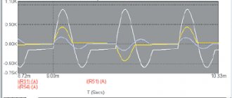
The diagram above shows the inrush current characteristic for direct starting. With this connection, the temperature increase in the windings of the machine is minimal.
The connection is made using a contactor (starter). The circuit uses an overload relay to protect the electric motor. However, this method is applicable when there are no current restrictions.
During the start of the machine, the starting torque is limited in order to smooth out a sharp jerk, as a result of which the mechanical parts of the drive and connected mechanisms may fail.
For this reason, manufacturers of large electric motors prohibit direct starting.
Soft start methods
The soft start of a commutator motor discussed above refers to the classic rheostat method, suitable for both direct and alternating current. Its negative aspects are the loss of a significant part of the power for heating the rheostat resistance and the bulkiness of the device. Therefore, this method is practically and economically justified only for starting the electric drive, but not for regulating the operating speed parameters. In general, starting drive devices and power tools can be done using other methods using:
- transformers;
- semiconductor switches.
The use of transformers is only permissible for alternating current objects. Its advantage is increased electrical safety when working with power tools. The disadvantage of this method is its rather large size and cost, even when manufactured independently.
The use of semiconductor switches is the most modern and inexpensive way to get a smooth start. Their main feature is the absence of mechanical contacts and high switching speed. Power switches are capable of handling high current loads and voltages. They practically do not heat up, consume minimal electricity and are the best option for electric motors of modern electric tools. There are three types of power switches:
- thyristors and triacs;
- MOSFET field effect transistors with isolated MOS gate;
- IGBT transistors.
Thyristors and triacs are designed to regulate power in circuits with variable current values. Powerful MOSFET field-effect transistors control the parameters of the mains current by changing the width of the opening pulses. This type of device finds its application in DC power supply. For high power tools, IGBT bipolar transistors with an insulated gate are used.
Power supply and device check
It is better to use a seven-amp 12 V battery as a power source. Current is supplied to the circuit through a fuse with a parameter of 30 A. The generator speed ranges from 0 to 420 rpm. If a wheel with a cross-section of 20 cm is pulled onto the generator pulley, a maximum speed of 16 km per hour is ensured.
Next, the generator is connected. The most basic method can be used to estimate the torque that it is capable of developing. To do this, you need to try to lift a load suspended by a rope to the generator pulley.
Two 5-liter bottles filled with water, if you use a diameter of 5.5 cm, the generator can easily lift the containers to a height of 50 cm for about 3 seconds. The current from the battery shows 16 Amperes, the voltage drops to 11 V. It turns out that the battery is rather weak for this load.
It turns out that a torque of approximately 2.75 newtons per meter is guaranteed, with 3 revolutions per 1 second shown.