Commutator motor design - alternating current
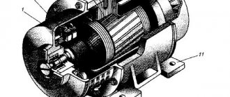
A general idea of the structure of an AC commutator motor can be clearly obtained from this schematic representation in Fig. 1.
Typical malfunctions of this type of electric motors include the following reasons:
and bearing wear.
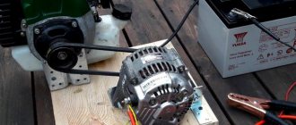
The AC commutator motors that we all know - from vacuum cleaner photo 1 and other household appliances with such motors - are subject to:
and thermal overloads, and in some cases parts must be repaired or completely replaced.
Brushed Motor Diagram - AC
This figure shows a universal diagram of the commutator motor Fig. 2. The circuit has three wire outputs from two stator windings, for connection to both alternating and direct voltages, that is, the motor is capable of operating on both direct and alternating current. Fig.2
The diagram shows the following designations:
Two ends of the wire from the three terminals of the stator windings are also needed to connect the smoothing filter of the capacitor.
Winding resistance - commutator motor
To measure the resistance of the stator windings of a commutator motor, you need to alternately connect the probes of the measuring device to the wire leads of photo 2.
Measurements of the resistance of the stator windings are carried out in order to determine their integrity or a break in the burnout of the wire in the winding.
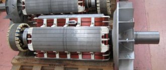
To measure the resistance of the rotor windings of a commutator motor, the resistance of the lamellas of the beginning and ends of the rotor windings connected to the metal plates is measured - on the collector photo 3, fig. 3.
And to check the absence or short circuit of the winding to the body of the rotor magnetic circuit, you need to connect one end of the probe of the device to the collector plate and connect the second probe to the magnetic circuit (Fig. 4.
When the rotor winding is short-circuited to the magnetic core body, the resistance for this section will take on a zero value.
In this topic, you got acquainted with the device and methods of diagnosing a commutator electric motor, and that’s not all.
The design of a modern car involves a commutator motor, a unit that uses contacts to determine the position of the rotor. Current trends in the global automotive market boil down to the complete replacement of power plants powered by internal combustion of fuel with electric motors. In recent years, calls for increasing the level of harmful emissions into the atmosphere have been heard almost daily, and this strengthens the position of electric units.
The operating principle of an electric motor is to convert electrical energy into mechanical work. If we compare units with internal combustion engines, electric motors are preferable; the advantage is: compactness, simplicity, durability, environmentally friendly and a lot of other advantages.
The design of a modern car involves a commutator motor, a unit that uses contacts to determine the position of the rotor.
Electric car Tesla model S:
Connection diagrams for single-phase asynchronous motors
With starting winding
To connect a motor with a starting winding, you will need a button in which one of the contacts opens after switching on. These opening contacts will need to be connected to the starting winding. In stores there is such a button - this is PNDS. Its middle contact closes for the holding time, and the two outer ones remain in a closed state.
Appearance of the PNVS button and the state of the contacts after the “start” button is released"
First, using measurements, we determine which winding is working and which is starting. Typically the output from the motor has three or four wires.
Consider the option with three wires. In this case, the two windings are already combined, that is, one of the wires is common. We take a tester and measure the resistance between all three pairs. The working one has the lowest resistance, the average value is the starting winding, and the highest is the common output (the resistance of two windings connected in series is measured).
If there are four pins, they ring in pairs. Find two pairs. The one with less resistance is the working one, the one with more resistance is the starting one. After this, we connect one wire from the starting and working windings, and bring out the common wire. A total of three wires remain (as in the first option):
- one from the working winding is working;
- from the starting winding;
- general.
We work further with these three wires - we use them to connect a single-phase motor.
With all these
- Connecting a single-phase motor with a starting winding via the PNVS button
connecting a single-phase motor
We connect all three wires to the button. It also has three contacts. Be sure to place the starting wire on the middle contact (which closes only during the start), the other two - on the outermost (arbitrary). We connect a power cable (from 220 V) to the extreme input contacts of the PVNS, connect the middle contact with a jumper to the working one (note! not to the common one). That's the whole circuit for switching on a single-phase motor with a starting winding (bifilar) through a button.
Condenser
When connecting a single-phase capacitor motor, there are options: there are three connection diagrams and all with capacitors. Without them, the engine hums, but does not start (if you connect it according to the diagram described above).
Connection diagrams for a single-phase capacitor motor
The first circuit - with a capacitor in the power supply circuit of the starting winding - starts well, but during operation the power it produces is far from rated, but much lower. The connection circuit with a capacitor in the connection circuit of the working winding gives the opposite effect: not very good performance at start-up, but good performance. Accordingly, the first circuit is used in devices with heavy starting (concrete mixers, for example), and with a working condenser - if good performance characteristics are needed.
Circuit with two capacitors
There is a third option for connecting a single-phase motor (asynchronous) - install both capacitors. It turns out something between the options described above. This scheme is implemented most often. It is in the picture above in the middle or in the photo below in more detail. When organizing this circuit, you also need a PNVS type button, which will connect the capacitor only during the start time, until the motor “accelerates”. Then two windings will remain connected, with the auxiliary winding through a capacitor.
Connecting a single-phase motor: circuit with two capacitors - working and starting
When implementing other circuits - with one capacitor - you will need a regular button, machine or toggle switch. Everything connects there simply.
Selection of capacitors
There is a rather complex formula by which you can calculate the required capacity accurately, but it is quite possible to get by with recommendations that are derived from many experiments:
- The working capacitor is taken at the rate of 70-80 uF per 1 kW of engine power;
- starting - 2-3 times more.
The operating voltage of these capacitors should be 1.5 times higher than the network voltage, that is, for a 220 volt network we take capacitors with an operating voltage of 330 V and higher. To make starting easier, look for a special capacitor for the starting circuit. They have the words Start or Starting in their markings, but you can also use regular ones.
Description of the commutator motor
First, before considering installation options, let’s clarify what the concept of a commutator motor means. An electric motor is a device that converts electrics into mechanics and vice versa. If the motor winding has a connecting link with the collector unit and takes part in the transformation of energy, then such a unit is called a collector unit.
Jacobi B.S. (1801-1874) inventor of the first commutator engine in 1837.
Electric motor components:
- The rotor, a part of the motor, is subject to rotation;
- The stator, a part of the motor, remains in a stationary position;
- An inductor, a piece of an aggregate that, in order to generate a torque, participates in the formation of a magnetic field flow. The inductor consists of: magnets, a set of turns. The mechanism is made as part of a rotor or a fixed part;
- An anchor, a unit that supports the movement of the load, ordered movement of particles, electric charge carriers and, due to induction, generates an electromotive force. The armature function is performed by either the rotor or the stator;
- Brushes, a part that is part of the electrical circuit through which current is transmitted to the armature. The material from which brushes are made is usually graphite. The motor contains at least two brushes for the “positive” and “negative” poles;
- The commutator is the part of the unit that is in contact with the brushes and distributes the current.
The name of the unit comes from the name of the electric motor rotor assembly - the commutator. Visually, the collector is a part in the form of a cylinder, which consists of copper plates isolated from each other.
Important! Experienced users know that to increase the service life of a new installation, break in the commutator motor. To do this, the unit operates at 15-20% power without load for 10-15 minutes. This will avoid burning out the collector and will give a power increase of 10-15%.
Universal commutator motor.
Read also: DIY tool organizer for the wall
Operating principle of a commutator motor
In order to understand how a commutator motor works, let’s remember electromagnetic induction. Let's place a conductor on the axis of rotation, with a circulating current inside it, between the magnets, the north and south poles. The conductor rotates in the direction of current flow; this is the operating principle of a commutator motor. Power passes through the brushes to the end of the conductor. Half a turn, and the current switches, promoting continuous rotation in a given direction. The commutator motor is equipped with several conductors, so the circumference of the commutator is divided into contacts.
From the stator, current passes to the rotor windings through a series connection, brushes and commutator. Commutator motors are used in products where rotation speed is important. The motors are not heavy, with relatively small overall dimensions.
The principle of operation of a commutator motor.
Important! A commutator motor is capable of working in reverse order, converting mechanical energy into electrical energy. In this case, the role of the installation is a generator.
Brushless electric motor
In a typical brushless electric motor, the rotor is made of permanent magnets rotating around a stator with electromagnets. The controller of such a motor converts direct current into alternating current. This type is mechanically simpler than brush type, because it eliminates the complexity of transmitting electricity to the rotating motor rotor. The motor controller can monitor the position of the rotor using Hall effect sensors and can very precisely control timings, phases, etc., the current on the rotor windings can optimize torque, conserve energy, regulate speed and even perform some braking.
The advantages of brushless motors are long service life, no maintenance required and high efficiency. Disadvantages of brushless motors: high production cost and more complex speed controller.
Types of commutator motors
For ease of perception in any area, there is a classification of products according to criteria, features, and functionality. As for collector installations, classification takes place according to different parameters.
Scheme of a universal commutator motor.
When classified by nutrition:
- Universal commutator motor;
- Collector unit (direction of movement of charged particles in an electric field = const);
- With permanent magnet inductor;
- With inductor on excitation coils:
- Excitation coil (independent winding type);
- Excitation coil (parallel winding type);
- Excitation coil (series winding type);
- Excitation coil (mixed winding type).
Universal collector unit.
The units are used in everyday life; a 220V AC commutator motor is used in household appliances. The motor consumes direct and alternating current. Popularity in use is due to reverse, rotation speed adjustment, and the need for a frequency above 3000 rpm.
Using a single-phase AC commutator motor, the stator and rotor windings are connected in series or parallel. No one makes the last connection option anymore. The universal single-phase collector unit works with alternating and direct current.
Disadvantages of the universal mechanism:
- Unit cost;
- Difficulty of maintenance;
- Noisy operation, complex controls, radio interference;
- The useful action is lower than necessary if an alternating current source is used;
- Wear of brushes due to the formation of sparks.
Collector unit (current = const).
Permanent magnet inductor.
The design difference from the universal installation is the use of magnets rather than field coils. The unit is popular and more widespread than other types of collector installations. The positive point is the cost and simplicity of the design. In addition, the device is easy to operate. The stumbling block is the magnets used, which are directly related to the power characteristics of the installation. The installation is affected by the field generated by the magnets.
| Positive aspects | Negative aspects |
| Significant torque at low speed; Wide range of adjustments; The price of the unit is affordable for consumers. | Low power; Aging of magnets, loss of properties. |
Commutator motor with permanent magnet inductor.
Excitation coils (independent and parallel)
The name of the type was obtained as a result of independent power supply. The peculiarity is that for torque to occur, the power supply of the inductor and the armature must be different, otherwise the rotor of the installation will not spin.
If it is not possible to organize the supply of different currents, then the connection is made in parallel. Both types are the same in terms of characteristics. The torque of power plants is high (even at low rotation), and as the frequency increases, the torque decreases. Feature: independence of the coil and armature. For the unit to fail, it is enough for the current exciting the coil to drop to the value “0”.
Independent excitation circuit:
| Positive aspects | Negative aspects |
| There are no magnets, so time does not affect the performance of the unit; Low speed - high torque; Easy adjustment, organized by the regulator. | The price is too high in comparison with opponents; A drop in the excitation coil current below the limit value is fraught with breakdown. |
Parallel excitation circuit:
Excitation winding (series type)
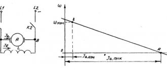
Sequence assumes equal current value. When the stator current is below the calculated value, the power of the magnetic flux decreases. The increase in load is comparable to the increase in flux power, until the limiting level is reached, when the increase in current does not increase the magnetic flux.
This feature does not allow the engine to start if the calculated load is below 25%. Having done this, there will be a sharp uncontrolled increase in rotation speed. This feature has left its mark on the use of the units; however, if the installation power is below 200W, the load may drop, even to idle speed.
| Positive aspects | Negative aspects |
| There are no magnets, so time does not affect the performance of the unit; The torque value is high, while the speed is insignificant. | The cost is too high, opponents are cheaper; The torque value decreases with increasing speed; Difficulties in adjusting the rotation speed of the unit; Operation without load leads to breakdown of the unit. |
Series excitation circuit.
Excitation winding (mixed type)
In such units, two coils are installed, connected in series and in parallel. The first has the status of the main one due to the ability to use a greater force of magnetism, the second has the status of an auxiliary one. It is possible to connect the coils using a counter or coordinated method. The selected connection determines what the field intensity will correspond to.
Read also: What dowels for timber 150 150
You can connect a commutator motor if you need to obtain a constant frequency, or increase speed when the load increases.
Mixed excitation circuit.
| Positive aspects | Negative aspects |
| There are no magnets, so time does not affect the performance of the unit; Low speed - high torque; Reliability, tolerates boundary loads well; Simple control. | High price. |
The next step in the development of electric motors was brushless motors. The difference between a brushed motor and a brushless motor is that the latter lacks both a commutator and brushes. The function of the rotor in the engine is performed by magnets that are located around the shaft, and the windings are also located there. The rotor position is controlled by a sensor. Information from the sensor is processed by the computer. The unit has the positive aspects inherent in installations with a collector; it is not maintained; the only negative aspect is the high cost.
A vacuum cleaner, coffee grinder, drill, hammer drill, trimmer is not a complete list of equipment that uses the conversion of electrical energy into mechanical energy to operate household devices.
They contain complex technical components and require skillful handling, periodic inspection, and proper maintenance. When handled carelessly, various breakdowns occur.
The material in the article provides advice to a home craftsman working with electric tools or planning to independently repair an electric motor with a brush mechanism and commutator. The text is visually supplemented with diagrams, pictures and videos.
The information provided is collected in order to draw the attention of users to the rules for operating household appliances with a commutator motor. It will help you consciously identify emerging defects in a working circuit and promptly eliminate them.
Brushless motor vs brushed motor
For several years now, we have seen the brushless motor dominate the advanced electric motor industry. Does it really matter to use a brushless motor? Yes, sure. There is a significant difference between them.
Let's look at the basics of a DC motor. DC Motor - All about magnets and electromagnetism.
Oppositely charged magnets attract each other. The basic idea of a DC motor is to keep the opposite charge of a rotating component attracted to the stationary magnets (stator) in front of it so that it generates a constant attraction. This forward thrust movement is caused by the physical behavior of electromagnetism.
Operating principle of the motor
It is based on the principle that when a current-carrying conductor is placed in a magnetic field, it experiences a mechanical force, the direction of which is given by Fleming's left hand rule, and its magnitude is determined by the force, F = BI l newton Where B is the magnetic field / m2 . I is the current in amperes, and l is the length of the coil in meters. Force, current and magnetic field are in different directions.
Layout and operating principle
The moving part of a commutator motor, like any other, is mechanically balanced and secured in rotation bearings mounted in a stationary frame.
The stationary stator and rotating rotor have their own windings made of insulated wire. An electric current flows through them, creating magnetic fields with their own poles: north N and south S.
The interaction of these two electromagnetic fields creates rotation of the rotor.
Since voltage must be constantly supplied to both windings, and the rotor rotates, a special device is mounted for it: a commutator with a brush mechanism.
Brush electric motor
A brush motor generates torque directly from power applied to it using an internal commutator, stationary magnets (permanent or electromagnetic), and rotating electromagnets.
The advantages of brushed motors are: low production cost, high reliability, and easy speed control. Disadvantages of brushed motors: high operating costs and short service life with high intensity use.
Maintenance includes regular replacement of the graphite brushes as well as cleaning or replacing the commutator. These components are important for transmitting electrical energy to the rotor winding.
Electrical diagram
For practical work, it is convenient to use two types of its representation:
Simplified display
The method allows you to very simply imagine the connection of all motor windings to the electrical network diagram.
The switch breaks both phase and zero potentials or one of them. Through the brushes with the commutator, a current circuit is created along the rotor windings.
Schematic diagram
Depending on the design features of the stator and rotor windings, they may have additional taps for powering various control and automation devices of the commutator motor or do without them.
Thermal protection prevents overheating of the motor winding insulation. It removes the supply voltage when the sensor is triggered, stopping the rotation of the rotor and actuator.
The tachogenerator allows you to judge the speed of rotation of the rotor. For some engines it is replaced with a Hall sensor. To transmit signals to these devices, collector plate contacts are also used.
Features and design of DPT
A DPT is a rotating electrical machine powered by direct current. Depending on the direction of power flow, a distinction is made between an engine (an electric motor with electrical and mechanical power) and a generator (an electrical generator supplied with mechanical power as well as electrical energy). DCTs can be started under load and their speed can be easily changed. In generator mode, the DPT converts the AC voltage supplied by the rotor into a pulsating DC voltage.
History of invention
Based on the development of the first voltaic cells in the first half of the 19th century, the first electromechanical energy converters were direct current machines. The original form of the electric motor was developed in 1829, and in 1832 the Frenchman Hippolyte Pixie built the first generator. Antonio Pacinotti built a DC electric motor with a multi-component commutator in 1860. Friedrich von Hefner-Alteneck developed the drum anchor in 1872, which opened up the possibility of industrial use in the field of large-scale engineering.
In subsequent decades, such machines, due to the development of three-phase alternating current, lost their importance in large-scale mechanical engineering. Synchronous machines and low maintenance induction motor systems have replaced them in many applications.
Engine design
To understand the principle of operation of a DCT, you must first study its design features, one of which is that a rotating conductive circuit is installed in the magnetic field of a permanent magnet.
Simplifying this structure, we can say that the engine consists of two main components:
- The main magnet (permanent magnet) that is attached to the stator. A magnetic field can also be electrically generated. The stator contains the so-called exciting windings (coils).
- A conductive loop (reinforcement) on the armature core, usually consisting of laminated metal sheets.
Both designs are called externally excited DC motors. The electrodynamic law indicates that a current-carrying loop of a conductor in a magnetic field represents a force [F], depending on the current [I] and the magnetic field strength [B]. A current-carrying conductor is surrounded by a circular magnetic field. If you combine the magnetic field of a magnetic field with the magnetic field of a conducting loop, you can find a superposition of the two fields, as well as a resulting force effect.
The armature winding consists of two halves of the coil. If a DC voltage is applied to the two ends of the armature winding, moving charge carriers can be imagined to enter the lower half of the coil from the upper half of the coil.
Each current-carrying coil develops its own magnetic field, and the magnetic field of the permanent magnet is superimposed on the magnetic field of the lower half of the coil and the field of the upper half of the coil. The field lines of a permanent magnetic field are always in the same direction , they always point from north to south pole. In contrast, the fields of the two halves of the coil have opposite directions.
On the left side of the field half of the coil, the field lines of the exciter field and the coil field have the same direction. Due to this force effect, a torque is created in the opposite direction at the lower and upper ends of the reinforcement, which causes a rotational movement of the armature.
The anchor is a so-called I-beam anchor. This design got its name because of its shape, which resembles two compound “Ts”. The armature coils are connected to the commutator (collector) boards. The supply of current to the armature winding is usually through carbon brushes, which provide sliding contact with the rotating commutator and supply electricity to the coils. The brushes are made from self-lubricating graphite, partly mixed with copper powder for small motors.
Problem areas of the structure
Most often, malfunctions can occur in:
- bearings:
- brush commutator unit;
- layer of insulation of windings and wires.
Bearings
Their location is carried out at the edges of the rotor in such a way as to transmit the axial torque load as much as possible.
In ordinary household tools, they can be damaged for two main reasons:
- from incorrect load application:
- as a result of pollution.
Directions of effort
Bearings in household power tools are generally not designed to support lateral loads. From their frequent use, for example, when, when working with a drill, they do not load the end of the drill, but cut slot holes on its side, shaft beating is transmitted to the bearing mechanism, creating additional play of the balls in the cages.
Working in a polluted environment
The commutator motor has an air cooling system. The impeller, mounted on the rotor, takes air through special slots in the motor casing and drives it throughout the entire housing to remove excess heat from the heating windings. Warm currents are ejected through special holes.
If a dusty environment is created in the room, it will be sucked into the housing and penetrate the bearings and commutator-brush mechanism. There will be an abrasive effect on the parts that come into contact during rotation, their premature wear, as well as a violation of the electrical conductivity at the brush contacts.
Using a commutator motor for purposes other than its intended purpose, for example, collecting a flow of construction dust with a household vacuum cleaner instead of a construction one, is the most common cause of its breakdown.
Why do brushes spark?
Design features
When the engine is running, there is constant friction of the brushes against the contact plates of the commutator, which requires periodic inspection.
A slight layer of coal dust appears on the working surfaces of copper pads, as shown in the photograph. This is due to material consumption and brush wear.
This process always occurs when a commutator engine is running. Even with normal sliding of the brush, a slight break in the electrical current circuit is created. And this is always associated with sparking due to the occurrence of transient processes and the appearance of microscopic arcs. In addition, the windings have high inductive reactance.
Read also: How to solder polypropylene without a soldering iron
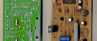
Therefore, a fully operational brush mechanism sparks during normal operation, which is not noticeable to the naked eye, but is felt by sensitive electronic devices: televisions, computers and other equipment. Noise suppression filters are always installed in their power supply circuit. An example is the electrical diagram of a microwave oven shown on the website with a highlighted green fragment.
Wear of brush material
The current-carrying part pressed against the collector plate is made of coal. Its volume wears out and its length decreases. This weakens the pressure force created by the expanding spring.
This process may or may not be taken into account in different brushed motor designs.
Rare samples
On the old 1960 engine shown as an example, the spring is compressed by screwing the dielectric cap.
The brush installation process is shown below.
Vacuum cleaner motor
The design of the brush mechanism described in the article about making a homemade trimmer has a screw for fixing the brush body.
Its installation is shown in the next photo. Please note that the brush itself was repeatedly ground down during long-term work and was replaced with a battery machined from a carbon electrode in the shape of the previous one.
When making brushes yourself, pay attention to the tightness of its entry into the socket and its perpendicular position to the shaft axis. If it is smaller, distortion will occur during operation. It will lead to excessive sparking and reduced engine life.
Therefore, it is advisable to use factory brushes from the manufacturer. There are other technical solutions to this issue.
How to check brush wear
The main method involves visual inspection. On the Internet you can find advice that recommends pressing the brush with a screwdriver while the engine is running and assessing the change in rotor speed.
This is a dangerous operation and should only be performed by trained and experienced personnel because:
- it is necessary to use protective equipment: work is performed under voltage;
- there is a possibility of creating a short circuit, because you will have to check both brushes in turn or simultaneously and use screwdrivers with insulated rods and tips.
If an external inspection shows that the length of the brush is greatly reduced or the working surface is chipped, then it simply needs to be replaced.
Contaminated collector
The formation of an excessive layer of coal dust with good conductive properties on the plates can cause them to short-circuit. It is necessary to remove it not only from the outer surface, but also from the spaces between them.
Graphite dust can be wiped off with a soft rag slightly moistened with alcohol or gasoline or removed with a thin wooden stick.
When the collector plates have lost their original shape and become grooved, they are restored using sandpaper with the finest grain on lathes. This is a complex operation that requires special equipment, but it can extend the life of the commutator motor.
Interturn short circuits in windings
Their formation on the stator or rotor sharply reduces the inductive reactance and leads to the appearance of additional sparks between different sections of the commutator and brushes. Additional overheating occurs.
Rotor winding
In some cases, the damaged section can be observed visually by a change in color. To perform electrical measurements, you will need an accurate ohmmeter. The testing technology is demonstrated in a video by the owner of altevaa TV “Checking the armature of a commutator motor.”
Repairing a damaged rotor winding is a complex operation. Sometimes it's easier to buy a new one.
Stator winding
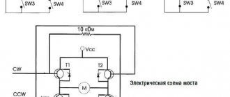
The malfunction can be detected by measuring the active component of the electrical resistance using a bridge circuit for each half-winding. But this is also quite difficult.
Breakdown of the dielectric insulation layer
Let us briefly touch on the reasons for the formation of defects and the protective devices that must be used.
How malfunctions occur
The copper wires of the cores of all windings are covered with a layer of varnish, which can be damaged by:
- carelessly applied mechanical loads;
- at elevated temperatures.
These same factors cause insulation defects in PVC-coated supply wires.
As a result of these influences, the following electrical circuit malfunctions appear:
- interturn short circuit, which creates an additional path for leakage current to flow, which significantly reduces engine performance;
- short circuit that can burn out wires.
Protective devices
Thermal relay
The overheat protection function built into many commutator motors works automatically. When equipment is switched off from frequent operation, it is necessary to look for the cause of the temperature increase. Unfortunately, some users try to block the thermal relay. This leads to a breakdown that is difficult to repair.