Reversing an engine is a change in rotor rotation to the opposite direction. You can change the direction of rotation for a DC electric motor, an asynchronous and commutator AC motor. It is difficult to imagine a device that does not use reverse rotation of the electric motor. Without a change in rotation, it is impossible to imagine the operation of a hoist, beam crane, winches, lifting mechanisms, elevators, valves, etc. The exception is devices such as sharpening machines, hoods, etc. In this article we will tell readers of the Sam Electric website how to reverse electric motors of different types.
Reversing DC motors
The easiest way to reverse a DC motor is that it has a permanent magnet stator. It is enough to change the polarity of the power supply so that the rotor begins to rotate in the opposite direction.
It is more difficult to reverse a motor with electromagnetic excitation (series, parallel). If you simply change the polarity of the supply voltage, the direction of rotation of the rotor will not change. To change the direction of rotation, it is enough to change the polarity only in the field winding or only on the rotor brushes.
To reverse high-power motors, the polarity should be changed at the armature. A break in the field winding while the motor is running can lead to a malfunction, because the resulting EMF has an increased voltage, which can damage the insulation of the windings. Which will lead to failure of the electric motor.
To reverse the direction of rotation of the rotor, bridge circuits using relays, contactors or transistors are used. In the latter case, you can also regulate the rotation speed.
The figure shows a circuit using transistors. To illustrate the operation, the transistors are replaced by switch contacts. Similarly, bridge circuits are made not on bipolar, but on field-effect transistors.
The efficiency of such a circuit is much higher than that of transistors. Control is carried out by a microcontroller or simple logic circuits that prevent simultaneous signaling.
Reversing motors with constant current
It is very easy to reverse power plants with direct current. To do this, just reverse the polarity, and the rotor will spin in the opposite direction.
A more difficult task is reversing a motor with electrical series or parallel excitation.
Simply changing the power polarity is not enough. It will be necessary to change the polarization in the exciting winding or on the rotor brushes.
For motors with high power, changing the armature polarity is applicable.
Breaking the exciting winding on a functioning motor is not allowed, because the resulting electric driving force has a high voltage, which will lead to insulation breakdown and, as a result, the motor will lose its functionality.
To perform reversal, relays, transistor bridges, or contactors are used. With a transistor bridge circuit, the rotating speed can be controlled and varied.
The picture shows a transistor circuit. To illustrate functionality, switching contacts are shown instead of transistors. Bridges for field-effect transistors are made identically.
The efficiency of this circuit is an order of magnitude greater than that of a transistor. Control is performed by a controller or logic circuits that prevent the simultaneous receipt of a signal.
Changing the direction of rotation of the rotor of an asynchronous motor
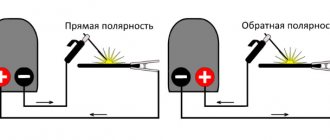
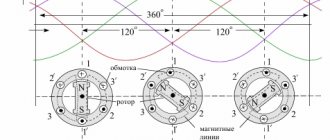
The most widespread in industry are asynchronous motors powered by a three-phase voltage of 380 volts. In order to reverse, it is enough to change any two phases.
A connection diagram based on two magnetic starters has become widespread. Actually for DC motors it is similar, but two-pole contactors or starters are used. This circuit is called “reversible starter circuit” or “reversible circuit for starting an asynchronous three-phase electric motor.”
When you turn on the KM1 starter with the “Start 1” button, voltage is directly supplied to the windings and the “Start 2” button is blocked from accidental activation by opening the normally closed contacts of KM-1. The motor rotates in one direction.
After turning off the KM1 starter with the “Stop” button or completely removing the voltage, you can turn on the KM2 with the “Start 2” button. As a result, line L2 is supplied directly through the contacts, and L1 and L3 are swapped. The “Start 1” button is blocked, since the normally closed contacts of the KM2 starter are driven and opened. The engine begins to rotate in the other direction.
The circuit is used everywhere to this day for connecting a three-phase motor in a three-phase network. The simplicity of the circuit design and the availability of components are its significant advantages.
Electronic control systems are the most widespread. Switching circuits, which are assembled on thyristors without starters. Although starters can be installed to remotely turn on or off in this circuit.
They are more complex, but also more reliable than contactor-based devices. For control, pulse-phase control systems (PFC) and frequency control systems are used. These are multifunctional devices, with their help you can not only reverse an asynchronous electric motor, but also regulate the rotation speed.
At home, it becomes necessary to connect a 380V to 220V motor with reverse. To do this, it is necessary to switch the star-delta windings. We looked at the differences between these schemes in more detail in an article posted on the site earlier:.
However, if a three-phase electric motor is supposed to be connected to a single-phase network, then a capacitor is used for this, which is connected according to the diagram below.
In this case, in order to reverse, it is enough to switch the network wire from B to terminal A, and disconnect the capacitor from A and connect to terminal B. It is convenient to do this using a 6-pin toggle switch. This is a typical connection of an asynchronous electric motor to a 220V network with a capacitor.
How to implement a reverse circuit?
To change the direction of rotation of the rotor, you need to swap 2 of the 3 phases of its winding. Then the electromagnetic field of the stator changes its direction of movement, while the rotor, in the initial period of time, moving by inertia, will begin to slow down until it finally stops. And only then will it spin in a different direction.
Replacing the polarity of the electric starting winding can be done with a control toggle switch according to the diagram. It can be selected with 2 or 3 fixed positions and 6 outputs. You need to select such a device based on the current load and permitted voltage.
It is preferable to pass current to the toggle switch from the auxiliary winding, which operates for a short time. The above will make it possible to significantly increase the working resource of the contact group.
Reversing an asynchronous motor with capacitor starting is best done according to the following scheme:
- During a difficult start, an additional capacitor is connected in parallel to the main capacitor, using the middle contact with a self-resetting NVD.
- In this example, the reverse toggle switch is switched only when the rotor is locked, and not when it is rotating.
- A random change in the direction of operation of a motor under voltage is associated with huge current surges, which depletes its motor resource. For this reason, the location of the reverse toggle switch on the equipment must be selected in such a way as to make it impossible to accidentally turn it on during operation. It is better to install it in some recessed place in the structure.
If the motor does not operate properly after assembling the circuit, you will need to double check that the wires are going to the correct switch terminals. And also make sure that the wiring is not loose or damaged.
It is recommended to use a magnifying glass to ensure that the connections are made correctly and that even the thinnest strand of wire does not accidentally touch another wire or terminal.
Connection diagram for a commutator motor with reverse
To reverse a commutator motor, you need to know:
- Not every commutator motor can be reversed. If a rotation arrow is indicated on the housing, then it cannot be used in reversible devices.
- All high speed engines are designed to rotate in one direction. For example, in an electric motor installed in angle grinders.
- For an engine that has low speeds, rotation can occur in different directions. Such motors are mounted in power tools, for example, electric drills, screwdrivers, washing machines, etc.
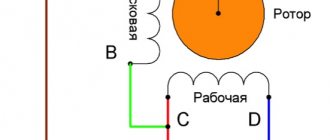
The figure shows a diagram of a universal commutator motor, which can operate on both direct and alternating current.
To change the rotation of the rotor, it is enough to change the polarity of the voltage on the rotor or stator winding, as in DC motors, from which universal machines are practically no different.
If you simply change the polarity of the supply voltage to the commutator motor, the direction of rotation of the rotor will not change. This must be taken into account when connecting the electric motor to the network.
You should also know that in high-power motors the armature winding is switched. When switching the stator windings, a self-induction voltage arises, which reaches values that can damage the motor.
Amateur designers use various types of engines in their crafts. They often use a brush motor from an automatic washing machine. These are convenient motors that can be connected directly to a 220 volt network. They do not require additional capacitors, and the speed can be easily adjusted using a standard dimmer. Six or seven pins are output to the terminal block.
Depends on engine type:
- Two go to the commutator brushes.
- A pair of wires come from the tachometer to the block.
- The field windings may have two or three wires. The third is used to change the rotation speed.
To reverse the motor from a washing machine, you should swap the leads of the field winding. If there is a third output, then it is not used.
How to reverse on a 12 volt motor
Hello everyone, probably many radio amateurs, like me, have more than one hobby, but several. In addition to designing electronic devices, I do photography, video shooting with a DSLR camera, and video editing. As a videographer, I needed a slider for video shooting, and first I’ll briefly explain what it is. The photo below shows the factory slider.
The slider is designed for video shooting on cameras and video cameras. It is analogous to the rail system used in wide-format cinema. With its help, a smooth movement of the camera around the object being photographed is created. Another very powerful effect that can be used when working with a slider is the ability to move closer or further from the subject. The following photo shows the engine that was chosen to make the slider.
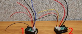
The slider is driven by a 12-volt DC motor. A diagram of a regulator for the motor that moves the slider carriage was found on the Internet. The next photo shows the power indicator on the LED, the toggle switch that controls the reverse and the power switch.
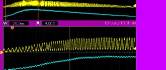
When operating such a device, it is important that there is smooth speed control, plus easy inclusion of engine reverse. The speed of rotation of the motor shaft, in the case of using our regulator, is smoothly adjusted by rotating the knob of a 5 kOhm variable resistor. Perhaps I am not the only one of the users of this site who is interested in photography, and someone else will want to replicate this device; those who wish can download an archive with a circuit diagram and printed circuit board of the regulator at the end of the article. The following figure shows a schematic diagram of a regulator for an engine: