One of the important parameters taken into account in electrical circuits is electrical capacitance - the ability of conductors to accumulate charges. The concept of capacitance is used both for a solitary conductor and for a system consisting of two or more conductors. In particular, capacitors consisting of two metal plates separated by a dielectric or electrolyte have capacitance.
Batteries are widely used to accumulate charges and are used as direct current sources to power various devices. The quantitative characteristic that determines the operating time of a battery is its electrical capacity.
What determines the capacitance and charge of a capacitor?
The capacitance of a capacitor is a physical quantity by which its ability to perform its functional tasks is assessed.
The practical value of capacitance is expressed in the ability of an electrical device to accumulate charge.
The voltage on the plates directly affects the quantitative characteristics of the charge on the plates. The formula for determining capacity looks like
C = q/U,
where C is the capacitance of the capacitor,
q - means the amount of charge on one of the plates,
U is the potential difference on the plates. The given calculation formula is largely theoretical in nature.
There is another definition of capacity, which is more useful in a practical sense.
The formula C = єS/d indicates its relationship with the area S of the plates, the distance between the plates d and the properties of the dielectric є.
It follows from the formula that the larger the area of the plates, the greater the charge that can be placed on them and the greater the distance between the plates, the weaker the charged particles will be attracted to each other, increasing their chances of leaving the plate.
The maximum dielectric constant of the material located between the plates increases the capacitance of the capacitor without changing the overall characteristics.
Capacitance of the capacitor
Further experiments with the distribution of electricity over the surface of an electrified conductor, carried out by Coulomb and other naturalists, made it possible to establish that a uniform distribution of electricity occurs only on a regular spherical surface. In general, the charge is uneven and depends on the shape of the conductor, being greater in places of greater curvature. The ratio of the amount of electricity on part of the surface of a conductor to the size of this surface is called the density (thickness) of the electrical layer. It was experimentally established that the electrical density and electrical force are especially high in areas of the surface that have the greatest curvature, especially at the tips.
Interesting material for familiarization: what are variastors.
The value characterizing the dependence of the potential of an electrified conductor on its size, shape and environment is called the electrical capacity of the conductor and is designated by the letter C. The electrical capacity of a conductor is measured by the amount of electricity required to increase the potential of this conductor by one:
It will be interesting➡ What is an electric field: an explanation in simple words
С = q/ϕ.
The unit of electrical capacity in the SI system is 1 farad (1 F). A farad is the electrical capacitance of a conductor, to which one coulomb of electricity must be supplied to increase its potential by one volt. A ball with a radius of 9·10 6 km would have an electrical capacity equal to 1 F, which is 23 times the distance from the Earth to the Moon. If a conductor is connected to a source of electricity of a certain potential, the conductor will receive an electrical charge depending on the capacitance of the conductor. Its capacity, and, consequently, the amount of electricity with which it is charged, increases if a second conductor connected to the ground is brought closer to it.
A structure consisting of two conductors separated by an insulator, with an electric field between them, all the lines of force of which begin on one conductor and end on the other, was called an electric capacitor. In this case, both conductors are called plates, and the insulating pad is called a dielectric. The process of accumulating charges on the plates of a capacitor is called charging. When charging, charges of equal magnitude and opposite sign accumulate on both plates.
Since the electric field of a charged capacitor is concentrated in the space between its plates, the electrical capacity of the capacitor does not depend on the surrounding bodies. The electrical capacity of a capacitor is measured by the ratio of the amount of electricity on one of the plates to the potential difference between the plates:
C = q/U.
1 F is the electrical capacity of such a capacitor, which can be charged with an amount of electricity equal to 1 C, up to a potential difference between the plates equal to 1 V. For example, the electrical capacitance of a flat capacitor in the SI system is determined by the relation:
С =εε 0 S/ d, where ε is the dielectric constant of the material located between the plates of the capacitor; ε 0 – dielectric constant of vacuum; S is the surface area of the plate (smaller if they are not equal); d – distance between plates.
If the plates of a charged capacitor are connected by a conductor, then the charges will move from one plate to another and neutralize each other. This process is called capacitor discharge. Each capacitor is designed for a specific voltage. If the voltage between the plates becomes too high, then discharge can occur directly through the dielectric (without a connecting conductor), i.e. This will result in a breakdown of the dielectric.
It will be interesting➡ What is electrical resistance
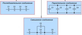
A broken capacitor is not suitable for further use. To obtain the electrical capacity of the required value, capacitors are connected into a battery. In practice, there are both parallel and series connections of capacitors.
The structure of a capacitor.
How does a capacitor work?
A capacitor consists of two or more metal plates with a dielectric material between them. The electrons begin to move, but are unable to overcome the dielectric, causing an electrical charge to accumulate between the plates.
Paper coated with aluminum oxide, mica, electrolyte, ceramics and similar materials have good dielectric properties.
The charges on different plates are the same in magnitude, but opposite in sign.
What is capacity
This value characterizes the ability of a capacitor device to accumulate electrical charge. It can be expressed as the quotient of the charge accumulated by the radio component and the potential difference between the plates.
Important! The concept of electrical capacitance applies not only to capacitors, but also to cables and other conductive elements. In this case, it depends on the dimensions and spatial configuration characteristics of the conductor, as well as environmental conditions.
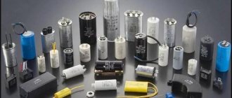
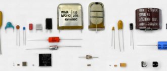
Types of capacitors
Capacitors differ in a number of parameters: by configuration, by the type of dielectric, by the material of the plates, by the type of change in capacitance (constant, variable, interlinear), by operating voltage. Below in the figure we consider the main types of electrical devices of various configurations.
Flat
The flat type of the device consists of two plates that are located parallel to each other. They are compact while maintaining large capacity.
The capacitance of a parallel-plate capacitor increases as the area of the plates increases and the distance between them decreases.
To calculate the capacitance of a flat capacitor, you should use the formula C = ε0 εS / d
Spherical
A spherical capacitor consists of two concentrically located spheres with a thin dielectric between them. The outer surface of the outer plate is grounded to create an electric field directly between the plates. Taking into account the geometry of the plates, the capacitance of a spherical capacitor is calculated using the formula
C = 4πεε0 Rr/ R - r, where R is the radius of the outer lining, r is the radius of the inner.
Cylindrical
A cylindrical capacitor is made of two hollow cylinders with different radii of their forming circles with a common axis. There is a dielectric between the outer surface of the small cylinder and the inner surface of the large one. To calculate the capacitance of a cylindrical capacitor, you can use the formula C = 2πєє0L/ ln (R2/R1),
where L is the length of the cylindrical plates,
R2 is the radius of the outer cylinder,
R1 is the radius of the inner cylinder,
ln - designation of logarithmic action.
Units
The physical quantity determined by the ratio of the charge q of one of the capacitor plates to the voltage between the plates of the capacitor is called the electrical capacity of the capacitor:
With a constant arrangement of the plates, the electrical capacity of the capacitor is a constant value for any charge on the plates. The unit of electrical capacity in the international system is farad (F). An electrical capacitance of 1 F is possessed by a capacitor whose voltage between the plates is equal to 1 V when the plates are charged with 1 C of opposite charges. . In practice, submultiple units of electrical capacitance are widely used: microfarads (μF), nanofarads (nF) and picofarads (pF):
- 1 µF = 10-6F;
- 1 nF = 10-9F;
- 1 pF = 10-12F.
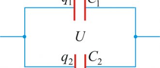
The electrical capacity of a capacitor is directly proportional to the area of the plates and inversely proportional to the distance between the plates. When a dielectric is introduced between the plates of a capacitor, its electrical capacity increases by e times. If two conductors isolated from each other are given charges q1 and q2, then a certain potential difference Δφ arises between them, depending on the magnitude of the charges and the geometry of the conductors.
The potential difference Δφ between two points in an electric field is often called voltage and denoted by the letter U. Of greatest practical interest is the case when the charges of the conductors are equal in magnitude and opposite in sign: q1 = – q2 = q. In this case, we can introduce the concept of electrical capacitance.
The electrical capacity of a system of two conductors is a physical quantity defined as the ratio of the charge q of one of the conductors to the potential difference Δφ between them. The value of electrical capacitance depends on the shape and size of the conductors and on the properties of the dielectric separating the conductors. There are configurations of conductors in which the electric field is concentrated (localized) only in a certain region of space.
Such systems are called capacitors, and the conductors that make up the capacitor are called plates. The simplest capacitor is a system of two flat conducting plates located parallel to each other at a small distance compared to the size of the plates and separated by a dielectric layer.
Such a capacitor is called a flat capacitor. The electric field of a parallel-plate capacitor is mainly localized between the plates (Figure 1); however, a relatively weak electric field also arises near the edges of the plates and in the surrounding space, which is called the stray field.
In a number of problems, one can approximately neglect the stray field and assume that the electric field of a flat capacitor is entirely concentrated between its plates (Figure 2). But in other problems, neglecting the stray field can lead to gross errors, since the potential nature of the electric field is violated.
It will be interesting➡ Electric circuit and its elements
According to the principle of superposition, the field strength created by both plates is equal to the sum of the strengths and fields of each of the plates. Outside the plates, the vectors and are directed in different directions, and therefore E = 0. The surface charge density σ of the plates is equal to q/S, where q is the charge and S is the area of each plate. The potential difference Δφ between the plates in a uniform electric field is equal to Ed, where d is the distance between the plates. From these relations we can obtain a formula for the electrical capacitance of a flat capacitor:
Thus, the electrical capacity of a flat capacitor is directly proportional to the area of the plates (plates) and inversely proportional to the distance between them. If the space between the plates is filled with a dielectric, the electrical capacity of the capacitor increases by ε times. Examples of capacitors with different plate configurations include spherical and cylindrical capacitors.
Electrical capacity is a characteristic of a conductor, a quantitative measure of its ability to hold an electric charge. In an electrostatic field, all points on the surface of a conductor have the same potential.
The potential φ (counted from the zero level at infinity) is proportional to the charge q of the conductor, i.e. the ratio of q to φ does not depend on q. This allows us to introduce the concept of electrical capacity. From an isolated conductor, which is equal to the ratio of the charge of the conductor to the potential:
C = q/ φ
Thus, the greater the electrical capacity, the more charge a conductor can accumulate at a given φ. Electrical capacity is determined by the geometric dimensions of the conductor, its shape and the electrical properties of the environment (its dielectric constant) and does not depend on the material of the conductor. In particular, the electrical capacity of a conducting ball in a vacuum is equal to its radius. The presence of other bodies near a conductor changes its electrical capacity, since the potential of the conductor also depends on the electric fields created by charges induced in surrounding bodies due to electrostatic induction.
In the unit system SGSE electrical capacity is measured in centimeters, in SI - in farads: 1F = 9 * 1011 cm. The concept of electrical capacity also refers to a system of conductors, in particular two conductors separated by a thin layer of dielectric - an electrical capacitor. Electrical capacity of a capacitor (mutual capacitance of its plates)
С = q/ (φ1 – φ2),
where q is the charge of one of the plates (the charges of the plates are equal in absolute value), φ1 – φ2 is the potential difference between the plates. The electrical capacity of a capacitor is practically independent of the presence of surrounding bodies and can reach a very large value with small geometric dimensions of the capacitors.
Polar
Polar capacitors are devices that have polarity, namely plus and minus. It is important that the positive contact is connected to the “plus” of the power source, and the negative contact to its “minus”. Reversing the polarity can even lead to a capacitor explosion. Polar ones include tantalum, ionistors, and capacitors with an electrolytic dielectric.
Tantalum
Tantalum capacitors, which are of the electrolytic type, use sintered tantalum powder, tantalum oxide, as a dielectric, hence their name. Such a dielectric reduces leakage current to almost zero.
The disadvantage is the inability to work in high voltage electrical circuits.
A tantalum capacitor includes 4 elements - anode, dielectric, electrolyte and cathode.
Unlike electrolytic ones, tantalum ones have a lower self-inductance, so they can be used at high frequencies.
The compactness of tantalum devices allows them to be used as components of wiring diagrams.
Ionistors
Ionistors belong to the category of electrochemical capacitors. The design feature lies in the combination of the properties of a conventional capacitor and a battery. The space between the electrodes is filled with a solid electrolyte based on rubidium and similar materials. This design eliminates spontaneous discharge of the ionistor.
Rapid discharge and charging make it possible to use it in some types of electrical circuits instead of a battery.
The battery, unlike the ionistor, will require considerable time to charge. The capacitance of the ionistor has the highest value among all electrolytic devices.
The ionistor only works with a constant voltage source.
Electrolytic
Electrolytic capacitors, in which one of the plates is made in the form of aluminum foil, have become widespread. The other plating is a solid or liquid electrolyte that ensures the movement of charged particles to preserve the oxide film.
The capacity of an electrolytic capacitor is by far the largest in terms of the capacitance to volume ratio of the element.
Electrolytic elements are installed in filters, but polarity is important.
Compared to tantalum capacitors, electrolytic capacitors have a significant leakage current.
The processes of transfer of charged particles occur slowly, which increases the amount of heat generated. Hence overheating and low service life.
Non-polar
Non-polar capacitors work correctly no matter how they are connected to an electrical circuit.
This is due to the similar structure of the materials that form the boundary between the plate and the dielectric. The sides are the same. All this leads to the fact that there is no need to observe polarity when installing the capacitor. As non-polar electrical devices, dry ones are mainly used, less often electrolytic ones, manufactured using modified technology.
Ceramic
Ceramic capacitors have high electrical performance, small dimensions and reasonable cost.
Elements are installed in the circuits of radio equipment. Ceramic capacitors are divided into
- with constant capacity
- tuning.
Elements with constant capacitance are installed in the circuits of generators and local oscillators. Tuning – used to adjust the parameters of oscillatory circuits. They are widely used due to the variety of capacities, a wide range of operating voltages, and standard sizes similar to ceramic devices from different manufacturers.
Film
A special feature of such devices will be a dielectric in the form of a film. The film is made from fluoroplastic, metallized paper, polypropylene, polycarbonate and similar materials. A metal film or foil is sprayed or pressed onto the dielectric.
Due to the large number of layers, an increase in area is obtained, and accordingly, the capacity increases significantly.
Among the advantages of a film capacitor, one should note the relatively high reliability and stability of the thermal state under loads caused by alternating current.
The disadvantages include the low value of dielectric permeability.
Film capacitors are used in DC circuits, all kinds of filters and resonant circuits.
Smd
In the control circuits of some types of boards, small SMD capacitors are used, shaped like small bricks. The radio element is installed on the board using the surface mounting rule. SMD devices come in the following types:
- electrolytic
- ceramic;
- tantalum.
Ceramic SMD capacitors with a dielectric with high permeability are marked with three letters. The first two letters indicate the lower and upper maximum permissible limits of the operating temperature range, the third letter is used to indicate deviations in the change in capacitance for the measured ranges.
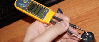
The small size of Smd capacitors does not always allow marking to be applied to the case or it will be very small.
In such cases, you cannot do without a special measuring device, for example, a multimeter.
Variables
Variable capacitors (VCA) consist of some sections of metal plates. One of them moves smoothly in relation to the second. During movement, it turns out that the moving plates (rotor) fall into the gaps of the stationary plate (stator). Thanks to the process, the area of overlap of one plate with another changes, as a result of which the capacitance of the capacitor changes. The dielectric layer in this case is air.
Capacitors installed in small devices use a solid dielectric, such as fluoroplastic or polyethylene.
In old radios, the device was used to tune the oscillating circuit of a working radio station to a specific frequency.
Maximum operating voltage on capacitor
The voltage supplied to the capacitor should not exceed the maximum, as dielectric breakdown may occur and the element may fail.
To analyze the operation of a capacitor in an alternating current circuit, the amplitude voltage value should be taken as a criterion for comparison with the maximum possible value.
This means that if some maximum voltage DC WV is indicated on it, then in reality when connected to the network it should be 1.4 less.
Magnitude and value of capacitor loss
Capacitor leakage current is a critical factor to use, especially when applied to power electronics. The loss is directly related to the properties of the dielectric.
No dielectric is capable of insulating metal plates with a 100% guarantee.
A current will always pass through the insulator, less or more depending on the properties of the dielectric and energy will be lost. In addition to the insulating properties of the dielectric, the following factors influence the leakage current:
- ambient temperature;
- shelf life of the capacitor without voltage, temperature;
- the magnitude of the leakage current is directly proportional to the voltage applied to the plates.
You can restore the functionality of a capacitor after long-term storage by applying operating voltage to it for several minutes.
At this stage, the oxidizing layer accumulates again and restores the functionality of the capacitor.
Capacitor in an electric current circuit
The principle of operation of a capacitor is simple - voltage is applied and a charge is accumulated. The drive behaves differently in two versions of the electrical circuit.
Permanent
If current is applied to a circuit with a capacitor connected to it, the needle on the ammeter will move, after which it will quickly return to its previous position. This is due to the fact that the device is charging quickly and the current has disappeared. Direct current cannot pass through plates separated by a dielectric. The practical use of a capacitor in such a circuit raises many questions. In direct current conditions, the capacitor functions, but for a short time. Transient processes in the form of charging and discharging remove all doubts. In DC electronic circuits, capacitors are one of the most common components.
Variable
When connecting alternating voltage, the poles of the capacitor change plus to minus with the frequency of the voltage supply. In this case, electrons move first to one and then to the other. During such a change, excess charge remains on the plates, which actually creates a current in the external circuit.
The capacitor in the AC circuit acts as a resistor.
Capacitor charge. Current
In terms of its purpose, a capacitor resembles a battery, but it is still very different in its operating principle, maximum capacity, and charging/discharging speed.
Let's consider the principle of operation of a flat-plate capacitor. If you connect a power source to it, negatively charged particles in the form of electrons will begin to collect on one plate of the conductor, and positively charged particles in the form of ions will begin to collect on the other. Since there is a dielectric between the plates, charged particles cannot “jump” to the opposite side of the capacitor. However, electrons move from the power source to the capacitor plate. Therefore, electric current flows in the circuit.
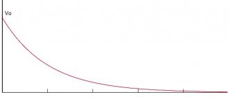
At the very beginning of connecting the capacitor into the circuit, there is the most free space on its plates. Consequently, the initial current at this moment encounters the least resistance and is maximum. As the capacitor fills with charged particles, the current gradually drops until the free space on the plates runs out and the current stops completely.
The time between the states of an “empty” capacitor with a maximum current value, and a “full” capacitor with a minimum current value (i.e., its absence), is called the transition period of the capacitor charge.
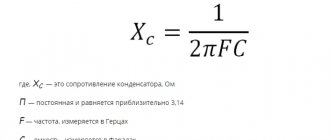
Capacitor resistance depending on
The resistance of the capacitor depends on the frequency of the voltage supplied to it and the capacitance value.
Frequencies and phase shift
A charge storage device of the same capacity exhibits different levels of resistance at different frequencies. It grows or decreases.
As the frequency of the input voltage increases, the resistance (also called capacitive) decreases.
At low frequencies there is a phase shift between the input voltage and the load voltage.
As frequency increases, the phase shift decreases.
When the frequency reaches a certain level, the phase shift tends to zero.
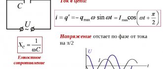
Xc = 1/ωС,
where ω is the circular frequency equal to the product 2πf,
C is the circuit capacity in farads.
Capacitor rating
The capacitance of a capacitor affects the charging and discharging process when alternating current passes through it.
A device with a smaller capacity will release charge faster and charge again.
The AC resistance will be higher than when charging and discharging slowly.
Hence the conclusion: capacitance is inversely related to the value of the capacitor.
Field away from the edges of the capacitor plates
Since the plates are charged with opposite charges of equal magnitude, the field strength between the plates is the sum of the field strengths of each of the plates.
Outside the capacitor plates, their fields are in opposite directions and the resulting field becomes zero. Thus: Eres=E++E−=2⋅σ2εε0Eres=E++E-=2⋅σ2εε0
We use the relationship between voltage and voltage and tension and the definition of surface charge density
E=UdE=Ud
σ=qSσ=qS
We get $
Ud=qεε0SUd=qεε0S
Where
C=qU=εε0Sd
It will be interesting➡ What is the difference between a starting capacitor and a working one?
Series and parallel connection of capacitors
The most popular type of capacitor connection is parallel. With this connection, the electrical capacity increases, but the voltage remains original.
Several capacitors can be connected to one point.
Since the electrical capacitance of the capacitors is equal to the area of the plates, the total capacitance with this type of connection is proportional to the sum of the capacitances of all capacitors in the circuit.
Message = C1+C2.
When capacitors are connected in series, the total capacitance decreases and the operating voltage of the capacitor increases.
The capacitors are connected so that only the first and last have access to the emf/current source of one of their plates. The charge is the same on all plates, but the outer ones receive a charge from the source, and the inner ones are formed due to the separation of charges that previously neutralized each other. We can calculate the capacitance of a series connection of two capacitors using the formula
Message = C1*C2/ C1+C2.
What is a parallel plate capacitor
The figure clearly illustrates the complexity of handling miniature markings. In some situations, you cannot desolder components from the board so as not to damage adjacent radio components due to excessive heating. Objective difficulties arise when inscriptions are mechanically removed or there is no accompanying documentation.
In any case, before moving on to practical recommendations, you should familiarize yourself with the theory. For simplicity, we consider a design of two plates. In a cylindrical design, linings rolled into a roll are used. However, if the length is long enough, fairly accurate calculations can be performed using the formulas presented below.
Under the following conditions, edge and other phenomena that can distort the determination of the capacitance of the capacitor can be neglected:
- the free gap (dielectric thickness) is significantly smaller than the dimensions of the plates;
- these elements are installed in parallel;
- there are no external electromagnetic fields, or their strength parameters are insignificant;
- the temperature range corresponds to the operating one.
If such a product is connected to a direct current source, charges of different polarities will accumulate on the plates over a certain period of time. Under these conditions, a field is formed with a uniform distribution of field lines. Its tension (E) is described by the expression:
E = q*e0* e*S,
Where:
- q is the amount of charge;
- e0 is the electrical constant, which is determined under ideal conditions (vacuum) as 8.854 * 10-12 F*m-1;
- e – permeability of the air layer or other dielectric (reference value);
- S – area of plates (plates).
Calculation formulas
Capacitance measurements are carried out using a specially derived formula. Electrical capacitance (C) is the ratio of the imparted charge (Q) to the resulting potential (U). The formula used to measure capacitance is: C=Q/V. The unit of measurement is the farad, which is denoted by the letter F. A capacitance of 1 farad will store a charge q = 1 coulomb with a voltage across the plates U = 1 Volt. Since capacitors have different types, the formulas are also different.
Through mathematical expressions
The mathematical expression for determining the capacitance of the capacitor C = q*U in SI units of each of the physical quantities included in the formula determines the value of 1 farad.
How does capacitance depend on the dielectric medium?
The effect of an insulator on the capacitance of a capacitor depends on the conductive properties of the substance inside that pad. The ability of an interplate conductor to insulate is called dielectric constant. Taking into account the characteristics of the dielectric, the formula for the capacitance of a flat device will become: C = є0є S/d, where under the letter є is the value of the dielectric constant of the insulator, and є0 is a constant value equal to the dielectric constant of vacuum (air).
In practice, a coefficient is used that indicates how many times the dielectric used reduces the electric field compared to air.
Table:
Electrical capacity
Electrical capacity is a scalar quantity that characterizes the ability of a conductor to accumulate electrical charge.
Electrical capacity:
- does not depend on q and U;
- depends on the geometric dimensions of the conductor, their shape, relative position, and electrical properties of the medium between the conductors.
The electrical capacitance of the conductor is called. the ratio of the charge of a conductor to its potential:
SI unit of capacitance: F (farad)
A capacitor has the property of accumulating and storing electrical energy. A capacitor is a system of two conductors separated by a dielectric layer, the thickness of which is small compared to the size of the conductors. The conductors are called capacitor plates. If the charges of the capacitor plates are equal in magnitude and opposite in sign, then the charge of the capacitor is understood as the absolute value of the charge of one of its plates.
Related material: How to check a capacitor
The electrical capacity of a capacitor is the ratio of the charge of the capacitor to the potential difference between the plates. The main components of electrical capacity are presented in the figure below:
The main components of electrical capacity.
Designation on electrical diagrams:
- The entire electric field is concentrated inside the capacitor.
- The charge of a capacitor is the absolute value of the charge on one of the capacitor plates.
Types of capacitors:
- by type of dielectric - air, mica, ceramic, electrolytic.
- The shape of the plates is flat and spherical.
- according to the capacity - constant, variable (adjustable).
Electrical capacity.
Electrical capacitance of a flat capacitor
where S is the area of the plate (plating) of the capacitor
- d - distance between plates
- εо - electrical constant
ε is the dielectric constant of the dielectric
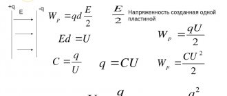
A capacitor is a system of charged bodies that has energy.
Energy of any capacitor:
where C is the capacitance of the capacitor, (F) W is the energy (J) q is the charge of the capacitor, (C) U is the voltage on the capacitor plates, (V
The energy is equal to the work done by the electric field when the plates of the capacitor are brought close together, or the work to separate positive and negative charges necessary when charging the capacitor. Capacitors are used to store electrical energy and use it during rapid discharge (photoflash), to separate DC and AC circuits, in radio engineering: oscillating circuit, rectifier and other radio-electronic devices.
How to measure capacitance
There are a number of ways to measure capacitance of a capacitor using instruments and various techniques. The article describes the use of a multimeter, oscilloscope, tester and bridge meters.
Multimeter
In the beginning, before you start measuring the capacitance of the capacitor, it must be discharged until the current completely disappears.
As an example: do this by shorting the terminals with a screwdriver.
If you neglect this nuance, the multimeter may break.
You can measure capacitance using a multimeter as follows: activate the “Cx” mode and set the measurement limit to 2000 pF, if any. On a standard device it is equal to 20 µF; Install the capacitor into the appropriate sockets in the multimeter or use probes to connect the capacitor. The capacitance value will be displayed on the device screen.
Oscilloscope
To measure, you will need, in addition to an oscilloscope, to assemble a circuit from the capacitor being tested, a resistor and a sinusoidal oscillation generator.
The connection points of the oscilloscope to the circuit are located before the resistor and after the capacitor.
The oscillator frequency changes until sinusoidal curves of equal amplitude are obtained on the oscilloscope screen. This is done for measurement accuracy. Imagine how to calculate the capacitance of a capacitor using amplitude voltage values? To do this, you need to use the formula UR/UC*2πfR and substitute the measured values into it. With its help, the leakage current of the capacitor is also calculated indirectly - by reducing the voltage across a previously known resistance. The oscilloscope is capable of calculating the capacitance of capacitors from 20 pF to 200 mkF.
A tester that does not have a direct function
To find an option for determining capacity using a tester without a capacity measurement function, you should pay attention to the formula for the instantaneous value of the current during charging or discharging i = C dU/dt.
The point here is that in addition to the tester and stopwatch, you should assemble a circuit with a power source,
a capacitor and a resistor with high resistance to increase the duration of the charging or discharging process. After taking all the readings from the tester and stopwatch, you can fairly approximately calculate and find out the capacity. Knowing how to determine the capacitance of a capacitor with modern instruments, it will not be difficult to understand the device from the times of the USSR. The display does not display numbers, but rather the deviation of the arrow, which is important to monitor closely. Capacitance measurements are carried out only on a discharged capacitor. Lead the probes to the contacts of the capacitor; if it is working, the arrow will initially deflect, after which it will take its original position as it charges. The speed of movement of the arrow depends on the volume of the container. If the tester's needle does not budge, or this value is minimal, or deviates and hangs in one position, this is an indicator of a faulty capacitor.
Bridge meters
The capacitance of the capacitor is measured by comparison with the reference capacitance. Why is a bridge circuit performed, where one arm works with a reference electrical device, the other with the one being tested. Bridge readings can be implemented on digital media.
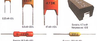
Capacitor markings
On the body of each capacitor there is a special marking - a letter and a number. Compared to resistors, capacitor markings indicating capacitance and capacitance deviation code are quite complex and varied. Sometimes the designations are written in capital letters - MF (microfarads), fd - farads. There are also positive and negative symbols on the housing to help determine the polarity of the capacitor.
Ways to designate a capacitor
The unit of measurement for the capacitance of a capacitor is the farad, so the letter Ф or F must be present on the body of the element:
- 1 millifarad = 10-3 farads = 1mF;
- 1 microfarad = 10-6 farads = 1 µF;
- 1 nanofarad = 10-9 farads = 1 nF;
- 1 picofarad = 10-12 farads = 1 pF.
If the element is not marked with a nominal value, then the integer value indicates that the capacity is indicated in picofarads. On the case, the capacity is indicated with a deviation; if the letter J is indicated, then the deviation range is less than 5%, the letter M is 20%.
Imported capacitor code
Imported devices, just like Russian ones, are marked in accordance with international standards. This regulatory document requires the application of a three-digit code. The first two digits indicate the capacitance in picofarads. The third digit indicates the number of zeros, for example, if the capacitance is less than 1 picofarad, the digit will look like “0”.
Code for surface mount capacitors
The marking of electrolytic SMD capacitors consists of capacitance and operating voltage. For example, 108V, where an electrical capacity of 10 pF and an operating voltage of 8 Volts are encoded. The plus sign is next to the stripe. There are three main encoding methods: a code of two or three characters (letters or numbers) that indicate the operating voltage and rated capacity. Indicators are indicated by a letter, and the number is a multiplier; four characters indicating voltage and rated capacitance. The first letter is the operating voltage, the next characters are the capacity in picofarads, the last digit is the number of zeros;
if the body area is large, the code is placed on two lines. The top line is the capacitance rating, the bottom line is the operating voltage.
Multiples of capacity units
Current unit
In most cases in electrical engineering, parts with small capacitance values are operated. Sometimes you will see designations such as 10uf capacitor. An inexperienced person may not immediately understand what the abbreviation uf means. It should be understood that the most common units in the description of capacitive elements are the following units: picofarad (or pF, it is equal to 10-12 F), nanofarad (nF, 10-9 F) and microfarad (μF, 10-6 F). Specifying the capacitance of a capacitor in uf means microfarads. It is advisable to purchase a table for converting measurement units of different scales to each other.
Multiple units are not used that often in practice. For some ionistor parts with a binary electrical layer, the capacitance indicator can be measured in kilofarads (kF, 1000 F). The value of standard capacitor elements usually does not exceed hundreds of farads.
Ionistor with a nominal value of 1 farad