Radio amateurs need to receive various radio signals. This requires the presence of a low-frequency and high-frequency generator. Often this type of device is called a transistor generator due to its design feature.
Operation of a transistor generator
Additional Information. A current generator is a self-oscillating device created and used to generate electrical energy in a network or convert one type of energy into another with a given efficiency.
Self-oscillating transistor devices
The transistor generator is divided into several types:
- according to the frequency range of the output signal;
- by type of signal generated;
- according to the action algorithm.
The frequency range is usually divided into the following groups:
- 30 Hz-300 kHz – low range, designated low;
- 300 kHz-3 MHz – medium range, designated midrange;
- 3-300 MHz – high range, designated HF;
- more than 300 MHz – ultra-high range, designated microwave.
This is how radio amateurs divide the ranges. For audio frequencies, they use the range 16 Hz-22 kHz and also divide it into low, medium and high groups. These frequencies are present in any household sound receiver.
The following division is based on the type of signal output:
- sinusoidal – a signal is issued in a sinusoidal manner;
- functional – the output signals have a specially specified shape, for example, rectangular or triangular;
- noise generator – a uniform frequency range is observed at the output; ranges may vary depending on consumer needs.
Transistor amplifiers differ in their operating algorithm:
- RC – main area of application – low range and audio frequencies;
- LC – main area of application – high frequencies;
- Blocking oscillator - used to produce pulse signals with high duty cycle.
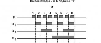
Frequency division
Probe circuit
As we can see, this is an ordinary blocking generator. It starts up easily - there are very few parts and it is difficult to mix anything up during assembly. What we need to build the circuit:
- Bread board
- LED of any color
- Momentary button
- 1K resistor
- Ferrite ring
- Varnished wire
- Socket for microcircuits
Picture on electrical diagrams
Blocking generator: operating principle
First, let's consider obtaining a sinusoidal type of signal. The most famous oscillator based on a transistor of this type is the Colpitts oscillator. This is a master oscillator with one inductance and two series-connected capacitors. It is used to generate the required frequencies. The remaining elements provide the required operating mode of the transistor at direct current.
Additional Information. Edwin Henry Colpitz was the head of innovation at Western Electric at the beginning of the last century. He was a pioneer in the development of signal amplifiers. For the first time he produced a radiotelephone that allowed conversations across the Atlantic.
The Hartley master oscillator is also widely known. It, like the Colpitts circuit, is quite simple to assemble, but requires a tapped inductance. In the Hartley circuit, one capacitor and two inductors connected in series produce generation. The circuit also contains an additional capacitance to obtain positive feedback.
Transistor generator circuits
The main area of application of the devices described above is medium and high frequencies. They are used to obtain carrier frequencies, as well as to generate low-power electrical oscillations. Receiving devices of household radio stations also use oscillation generators.
All of the listed applications do not tolerate unstable reception. To do this, another element is introduced into the circuit - a quartz resonator of self-oscillations. In this case, the accuracy of the high-frequency generator becomes almost standard. It reaches millionths of a percent. In receiving devices of radio receivers, quartz is used exclusively to stabilize reception.
As for low-frequency and sound generators, there is a very serious problem here. To increase the tuning accuracy, an increase in inductance is required. But an increase in inductance leads to an increase in the size of the coil, which greatly affects the dimensions of the receiver. Therefore, an alternative Colpitts oscillator circuit was developed - the Pierce low-frequency oscillator. There is no inductance in it, and in its place a quartz self-oscillation resonator is used. In addition, the quartz resonator allows you to cut off the upper limit of oscillations.
In such a circuit, the capacitance prevents the constant component of the base bias of the transistor from reaching the resonator. Signals up to 20-25 MHz, including audio, can be generated here.
The performance of all the devices considered depends on the resonant properties of the system consisting of capacitances and inductances. It follows that the frequency will be determined by the factory characteristics of the capacitors and coils.
Important! A transistor is an element made from a semiconductor. It has three outputs and is capable of controlling a large current at the output from a small input signal. The power of the elements varies. Used to amplify and switch electrical signals.
Additional Information. The presentation of the first transistor was held in 1947. Its derivative, the field-effect transistor, appeared in 1953. In 1956 The Nobel Prize in Physics was awarded for the invention of the bipolar transistor. By the 80s of the last century, vacuum tubes were completely forced out of radio electronics.
↑ Practice!
And now examples from practice - testing and tuning of the modernized amplifier “Radiotekhnika U-101”. First, let's apply a signal from the GPI directly to the input of the oscilloscope. Let me remind you that the oscilloscope input can be “closed,” i.e., not responsive to DC voltage, and “open,” responsive to both AC and DC voltage.
The first surprise is that the closed input of the oscilloscope noticeably distorts the 50 Hz square wave, this must be taken into account. The second surprise is that the rectangular signal reveals distortions in the oscilloscope itself in different parts of the screen, especially at the edges and corners of the screen, when moving the beam, etc. This also needs to be taken into account.
At a GPI repetition rate of 1000 Hz, the signal shape is almost ideal (pay attention to the position of the sweep switch, it can be used to judge the frequency of the supplied pulses). The lines on the screen are not completely horizontal, after taking the photo I had to take it apart and do a little adjustment to the tube.
↑ Effect of tone control
Next - images at the output of a full ULF under load at a power of several watts, filters and regulators are turned on in the amplifier.
When the RT is turned on (on the screen there is an oscillogram of a linear amplifier in the range of 20 Hz...20 kHz), the slightest change in the HF adjustment causes a noticeable rise or fall of the front in the indicated location.
It is possible to judge whether the frequency response in the middle position of the RT is linear or not, whether this can be achieved at all. A small decline is deceptive - the frequency response is linear, and the region below 20 Hz does not interest us (me). Therefore, instead of a 50 Hz GUI, you can use 100 Hz; in addition, at very low horizontal scanning frequencies (5 ms per cell or more), the image flickers, which is inconvenient. For simplicity, we will assume that the RT range is ±8 dB at 100 Hz and 10 kHz. Fragment excluded. The full version is available to patrons and full members of the community.
So that the picture is not too blissful, here is an example of unstable, “nervous” operation of an amplifier with insufficient correction. At the same time, the amplifier operated linearly in the range of 20...20000 Hz, and when tested with a G3-102 sine wave generator, some smooth hump was observed in the region of 80000 Hz.
Function transistor generator
Transistor voltage stabilizer
Functional generators based on self-oscillation transistors are invented to produce methodically repeating pulse signals of a given shape. Their form is determined by the function (the name of the entire group of similar generators appeared as a result of this).
There are three main types of impulses:
- rectangular;
- triangular;
- sawtooth.
A multivibrator is often cited as an example of the simplest LF producer of rectangular signals. It has the simplest circuit for DIY assembly. Radio electronics engineers often begin with its implementation. The main feature is the absence of strict requirements for the ratings and shape of transistors. This occurs due to the fact that the duty cycle in a multivibrator is determined by the capacitances and resistances in the electrical circuit of transistors. The frequency on the multivibrator ranges from 1 Hz to several tens of kHz. It is impossible to organize high-frequency oscillations here.
Obtaining sawtooth and triangular signals occurs by adding an additional circuit to a standard circuit with rectangular pulses at the output. Depending on the characteristics of this additional chain, rectangular pulses are converted into triangular or sawtooth pulses.
Principle of operation
Let's say that after turning on the power, the DD1.1 input goes low. This means that the output will be a high level, which goes to the input of DD1.2, the output of which, in turn, will again be a low level. Capacitor C1 is discharged. And it begins to charge through resistor R1, which is connected with the right terminal to the output of DD1.1 - to the point where the potential is high.
The process of charging capacitor C1
You have the right to ask: why does this current not flow to the input of element DD1.1 - after all, there is currently a low potential at this input? It seems that the logic element should eat up all the current, and the capacitor will get nothing. Answer: the problem is the high input resistance of the DD elements. A tiny part of the current is branched to their inputs, which can be neglected. By the way, thanks to this fact, the resistance R1 can be quite large, several mOhms, which makes it possible to obtain fairly low generation frequencies.
So, the voltage on C1 gradually increases, and at some point a sufficient “plus” will accumulate on the left plate, which will switch DD1.1 to state 1 at the input, 0 at the output. Immediately DD1.2 will change its state to the opposite: 0 at the input, 1 at the output. And the processes in the RC circuit will go in the opposite direction, until the voltage on the capacitor again switches DD1.1, followed by DD1.2, and the whole cycle repeats all over again. The description is somewhat simplified (near the switching point, slightly more complex processes occur there), but sufficient for an initial understanding.
Blocking generator
Current stabilizer on a transistor
At its core, it is an amplifier assembled on the basis of transistors arranged in one cascade. The scope of application is narrow - a source of impressive, but transient in time (duration from thousandths to several tens of microseconds) pulse signals with large inductive positive feedback. The duty cycle is more than 10 and can reach several tens of thousands in relative values. There is a serious sharpness of the fronts, practically no different in shape from geometrically regular rectangles. They are used in the screens of cathode-ray devices (kinescope, oscilloscope).
Pulse generators based on field-effect transistors
The main difference between field-effect transistors is that the input resistance is comparable to the resistance of electronic tubes. Colpitts and Hartley circuits can also be assembled using field-effect transistors, only the coils and capacitors must be selected with the appropriate technical characteristics. Otherwise, field-effect transistor generators will not work.
The circuits that set the frequency are subject to the same laws. For the production of high-frequency pulses, a conventional device assembled using field-effect transistors is better suited. The field effect transistor does not bypass the inductance in the circuits, so the RF signal generators operate more stably.
Period calculation
Now you can calculate the oscillation period of the multivibrator.
According to Ohm's law, voltage V1 is equal to:
Let's transform this formula through conductivity:
V1 = Vs / ( 1 + R1||R3 / R2 ) = Vs / ( 1 + y2 / (y1 + y3) ) = Vs ( y1 + y3 ) / ( y1 + y2 + y3 )
If all resistances are equal, then V1 = (2 / 3) Vs
Then we find the voltage V0, it is equal to:
Let's transform this formula through conductivity:
V0 = Vs / (1 + R1 / R2||R3 ) = Vs / ( 1 + ( y2 + y3 ) / y1 ) = Vs y1 / ( y1 + y2 + y3 )
If all resistances are equal, then V0 = Vs / 3
When the comparator is switched, capacitor C discharges exponentially. The discharge time is equal to the charging time and is equal to half the period. Then:
Hence T = 2 RC ln( V1 / V0 ) = 2 RC ln[ ( y1 + y3 ) / y1 ]
Finally, the period of the multivibrator is equal to:
In the special case, if R1 = R3 period T = 1.386 RC
If R3 = 2 R1 period T= 0.811 RC
Simple DIY sound generator
Let's consider the simplest example - the howler monkey. You only need four elements: a film capacitor, 2 bipolar transistors and a resistor for adjustment. The load will be an electromagnetic emitter. A simple 9V battery is enough to power the device. The operation of the circuit is simple: the resistor sets the bias to the base of the transistor. Feedback occurs through the capacitor. The tuning resistor changes the frequency. The load must have high resistance.
Sound generator circuit
With all the variety of types, sizes and designs of the considered elements, powerful transistors for ultra-high frequencies have not yet been invented. Therefore, generators based on self-oscillation transistors are used mainly for the low and high frequency ranges.
Connecting a group of LEDs to a 555 timer
Now that we have learned how to set the desired rhythm, let's assemble a small garland. In the new scheme, five LEDs will turn on for 0.5 seconds every second. For such a rhythm, Ra = 0, Rb = 7.2 kOhm. That is, instead of resistor Ra we can put a jumper.
The output of the 555 IC is too weak to light 5 LEDs at the same time. But in a real garland there can be 15, 20 or more of them. To solve this problem, we use a bipolar transistor operating in electronic key mode. Let's take the most common NPN transistor 2N2222. You can also use an N-channel field-effect transistor, for example 2N7000, in this circuit.
Our LEDs will require a current-setting resistor. The total current of five parallel-connected LEDs should be equal to I = 20 mA*5 = 100 mA. The supply voltage for the entire circuit is 9 Volts. On the red LED the voltage drops by 2 Volts. Thus, Ohm's law in this section of the circuit looks like:
100 mA = (9V-2V)/R;
hence R2 = 7V/0.1A = 70 Ohm.
Let's round the resistance to 100 Ohms, which can be obtained by connecting two 200 Ohm resistors in parallel. Or you can even leave one 200 Ohm resistor, the LEDs will just burn a little dimmer.
Video
Coffee capsule Nescafe Dolce Gusto Cappuccino, 3 packs of 16 capsules
1305 ₽ More details
Coffee capsules Nescafe Dolce Gusto Cappuccino, 8 servings (16 capsules)
435 ₽ More details
Smart plugs