To power household devices and industrial equipment, a source of electricity is required. It is possible to generate electric current in several ways. But the most promising and cost-effective today is the generation of current by electric machines. The easiest to manufacture, cheapest and most reliable in operation turned out to be an asynchronous generator, which generates the lion's share of the electricity we consume.
The use of electric machines of this type is dictated by their advantages. Asynchronous electric generators, unlike synchronous generators, provide:
- higher degree of reliability;
- long service life;
- efficiency;
- minimal maintenance costs.
These and other properties of asynchronous generators are inherent in their design.
Design and principle of operation
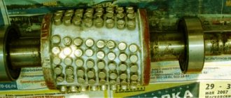
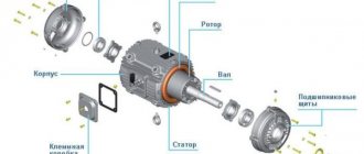
The main working parts of an asynchronous generator are the rotor (moving part) and the stator (fixed part). In Figure 1, the rotor is located on the right and the stator on the left. Pay attention to the rotor design. There are no copper wire windings visible on it. In fact, windings exist, but they consist of aluminum rods short-circuited to rings located on both sides. In the photo, the rods are visible in the form of oblique lines.
The design of short-circuited windings forms a so-called “squirrel cage”. The space inside this cage is filled with steel plates. To be precise, aluminum rods are pressed into slots made in the rotor core.
Rice. 1. Rotor and stator of an asynchronous generator
An asynchronous machine, the structure of which is described above, is called a squirrel-cage generator. Anyone who is familiar with the design of an asynchronous electric motor has probably noticed the similarity in the structure of these two machines. In essence, they are no different, since the asynchronous generator and the squirrel-cage electric motor are almost identical, with the exception of additional excitation capacitors used in generator mode.
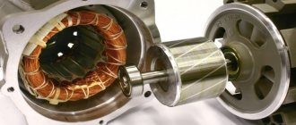
The rotor is located on a shaft, which sits on bearings clamped on both sides by covers. The entire structure is protected by a metal casing. Generators of medium and high power require cooling, so a fan is additionally installed on the shaft, and the housing itself is made ribbed (see Fig. 2).
Rice. 2. Asynchronous generator assembly
Operating principle
By definition, a generator is a device that converts mechanical energy into electrical current. It does not matter what energy is used to rotate the rotor: wind, potential energy of water, or internal energy converted by a turbine or internal combustion engine into mechanical energy.
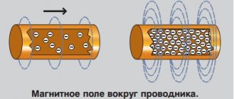
As a result of rotor rotation, magnetic field lines formed by the residual magnetization of the steel plates cross the stator windings. An EMF is generated in the coils, which, when active loads are connected, leads to the formation of current in their circuits.
In this case, it is important that the synchronous speed of rotation of the shaft is slightly (about 2 - 10%) higher than the synchronous frequency of alternating current (set by the number of stator poles). In other words, it is necessary to ensure asynchrony (mismatch) of the rotation speed by the amount of rotor slip.
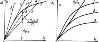
It should be noted that the current obtained in this way will be small. To increase the output power it is necessary to increase the magnetic induction. They achieve an increase in the efficiency of the device by connecting capacitors to the terminals of the stator coils.
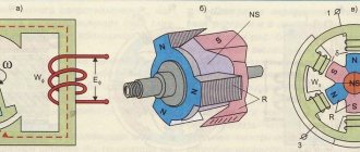
Figure 3 shows a diagram of a capacitor-excited asynchronous welding alternator (left side of the diagram). Please note that the field capacitors are connected in a delta configuration. The right side of the figure is the actual diagram of the inverter welding machine itself.
Rice. 3. Scheme of a welding asynchronous generator
There are other, more complex excitation schemes, for example, using inductors and a bank of capacitors. An example of such a circuit is shown in Figure 4.
Figure 4. Device diagram with inductors
Difference from synchronous generator
The main difference between a synchronous alternator and an asynchronous generator is the rotor design. In a synchronous machine, the rotor consists of wire windings. To create magnetic induction, an autonomous power source is used (often an additional low-power DC generator located on the same axis as the rotor).
The advantage of a synchronous generator is that it generates a higher quality current and is easily synchronized with other alternators of a similar type. However, synchronous alternators are more sensitive to overloads and short circuits. They are more expensive than their asynchronous counterparts and more demanding to maintain - it is necessary to monitor the condition of the brushes.
The harmonic coefficient or clearing factor of asynchronous generators is lower than that of synchronous alternators. That is, they generate almost pure electricity. The following operate more stable at such currents:
- UPS;
- adjustable chargers;
- modern television receivers.
Asynchronous generators provide reliable starting of electric motors that require high starting currents. In this indicator, they are actually not inferior to synchronous machines. They have fewer reactive loads, which has a positive effect on thermal conditions, since less energy is spent on reactive power. An asynchronous alternator has better output frequency stability at different rotor speeds.
Possibility of control
New power generators
Another feature of a synchronous generator (as well as an asynchronous one) is that the frequency and amplitude of the EMF induced at the stator terminals significantly depends on the rotor rotation speed.
Important! As the active load connected to the generator changes, the frequency of rotation of the generator shaft also changes in proportion to it, which leads to a change in the characteristics of the EMF created in the stator.
This drawback forces the installation of an electronic voltage and frequency regulator in synchronous and asynchronous devices, which ensures that these parameters are maintained at the proper level (the regulator diagram is given below).
AG voltage regulator circuit
Since the asynchronous generator operates on the principle of mismatched rotation of the fields of the moving and stationary parts, it is not possible to regulate the output parameters within the system. This is explained by the impossibility of organizing instantaneous voltage feedback by supplying part of the output signal from the stator to the rotor (only external voltage stabilizers can be used in AG).
This is another difference between asynchronous units and their synchronous counterparts, which in all other characteristics are very similar to the former.
Classification
Short-circuit type generators are most widespread due to the simplicity of their design. However, there are other types of asynchronous machines: alternators with a wound rotor and devices using permanent magnets that form an excitation circuit.
Figure 5 shows two types of generators for comparison: on the left, based on an asynchronous motor with a squirrel-cage rotor, and on the right, an asynchronous machine based on an IM with a wound rotor. Even a quick glance at the schematic images reveals the complex design of the wound rotor. The presence of slip rings (4) and a brush holder mechanism (5) attracts attention. The number 3 indicates the grooves for the wire winding, to which current must be supplied to excite it.
Rice. 5. Types of asynchronous generators
The presence of field windings in the rotor of an asynchronous generator improves the quality of the generated electric current, however, such advantages as simplicity and reliability are lost. Therefore, such devices are used as a source of autonomous power only in those areas where it is difficult to do without them. Permanent magnets in rotors are used mainly for the production of low-power generators.
DC Generators
The design of DC generators allows them to be used as electric motors. This requires electrical power to be supplied to the armature. DC electrical machines can be of the following types:
- with a self-excitation winding connected to the battery;
- independent type with shunt circuit (parallel excitation);
- independent serial connection circuit; parallel and serial connection refers to the connection diagram of the armature and stator windings.
A feature of most automotive DC generators is the use of the positive pole as a “ground”. DC generators have a number of disadvantages:
- low power;
- low efficiency;
- Regular maintenance is required;
- insufficient resource.
All these shortcomings led to the fact that DC electric cars gave way under the hoods of cars to more advanced AC voltage units. DC machines lasted the longest in railway transport, but even there they were replaced by three-phase AC devices.
Device
The DC generator is based on a massive housing 18, which acts as a stator. Pole windings 9 are installed inside. The slots designed to accommodate the windings are offset relative to the generator axis along a helical line.
Due to this, the uniformity of the magnetic flux is ensured and noise during operation is reduced. The stator winding is routed to terminal 6, marked Ш, and to the generator housing. Between the windings there is a rotating armature 19, equipped with a collector current-collecting part 4.
The armature has a shaft 10, which rests on two ball bearings 2. The bearings are installed in the front and rear covers - 16 and 1, respectively. To supply lubricant to the bearings, grease nipples 5 are provided.
To prevent lubricant leakage and dust ingress, seals 3 made of felt are used. The back cover has attachment points for brush holders 12, equipped with graphite brushes 11. To ensure that the brushes adhere to the commutator, springs 13 are used.
An example of the design of an automobile DC generator. There are positive and negative brushes. The positive part is located in the brush holder without an insulator and is connected to the generator housing. The negative brush is isolated from the other parts and has a lead to terminal 7 (marked with the letter Z). Access to the brushes for inspection and maintenance is possible through an inspection window, closed during operation of the device with a lid 20. There are generator models equipped with two pairs of brushes and additional stator windings. Brushes of the same polarity are connected to each other in a single circuit.
A pulley 15 is installed on the front part of the armature shaft, which is kept from turning by a key. The pulley is secured with a nut 14, which on some generator models is secured with a cotter pin. To cool the internal volume of the generator, a fan is used, the blades of which are shed on the drive pulley.
Electrical diagram
Below are three options for generator circuits, differing in the type of excitation:
- independent(s);
- parallel (b);
- mixed (in).
Typical circuits of DC generatorsSymbols:
- Ya1 and Ya2 – windings installed on the armature;
- D1 and D2 – additional windings of additional poles;
- Ш1 and Ш2 – shunt winding;
- C1 and C2 – series field winding;
- RH – load.
Principle of operation
The operating principle of a car generator is based on the process of inducing electromotive force in the rotating armature windings as a result of the influence of the stator magnetic field. Voltage is removed from individual half-rings, which allows the formation of rectified current without additional devices.
The simplest generator with permanent magnets.
Mounting and drive
Alternating current generators were installed on cars through a separate bracket or directly on the side of the engine crankcase. On lower valve engines, the device was mounted on the head of the block and was used to install the cooling system fan. With this installation scheme, the drive uses a belt drive from a pulley mounted on the engine crankshaft.
The generator support allows you to change the installation angle, ensuring belt tension. On large engines, generators could be driven by timing gears of the gas distribution mechanism.
Application area
The most common use of generator sets with a squirrel cage rotor. They are inexpensive and require virtually no maintenance. Devices equipped with starting capacitors have decent efficiency indicators.
Asynchronous alternators are often used as an autonomous or backup power source. Portable gasoline generators work with them, they are used for powerful mobile and stationary diesel generators.
Alternators with three-phase windings reliably start a three-phase electric motor, therefore they are often used in industrial power plants. They can also power equipment in single-phase networks. The two-phase mode allows you to save fuel on the internal combustion engine, since the unused windings are in idle mode.
The scope of application is quite extensive:
- transport industry;
- Agriculture;
- household sphere;
- medical institutions;
Asynchronous alternators are convenient for the construction of local wind and hydraulic power plants.
DIY asynchronous generator
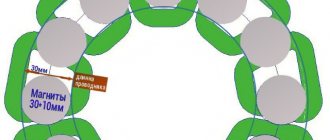
Let’s make a reservation right away: we are not talking about making a generator from scratch, but about converting an asynchronous motor into an alternator. Some craftsmen use a ready-made stator from a motor and experiment with the rotor. The idea is to use neodymium magnets to make the rotor poles. A workpiece with glued magnets might look something like this (see Fig. 6):
Rice. 6. Blank with glued magnets
You glue magnets onto a specially machined workpiece mounted on the electric motor shaft, observing their polarity and shift angle. This will require at least 128 magnets.
The finished structure must be adjusted to the stator and at the same time ensure a minimum gap between the teeth and the magnetic poles of the manufactured rotor. Since the magnets are flat, you will have to grind or sharpen them, while constantly cooling the structure, since neodymium loses its magnetic properties at high temperatures. If you do everything correctly, the generator will work.
The problem is that it is very difficult to make an ideal rotor in artisanal conditions. But if you have a lathe and are willing to spend a few weeks making adjustments and modifications, you can experiment.
I propose a more practical option - turning an asynchronous motor into a generator (see video below). To do this, you will need an electric motor with suitable power and an acceptable rotor speed. The engine power must be at least 50% higher than the required alternator power. If you have such an electric motor at your disposal, start processing. Otherwise, it is better to buy a ready-made generator.
For recycling you will need 3 capacitors of the KBG-MN, MBGO, MBGT brands (you can take other brands, but not electrolytic ones). Select capacitors for a voltage of at least 600 V (for a three-phase motor). The reactive power of the generator Q is related to the capacitor capacity by the following dependence: Q = 0.314·U2·C·10-6.
As the load increases, the reactive power increases, which means that in order to maintain a stable voltage U it is necessary to increase the capacitance of the capacitors, adding new capacitances through switching.
Video: making an asynchronous generator from a single-phase motor - Part 1 https://www.youtube.com/watch?v=ZQO5S9F72CQ
Part 2 https://www.youtube.com/watch?v=nDCdADUZghs
Part 3 https://www.youtube.com/watch?v=6M_w1b2xyM8
Part 4 https://www.youtube.com/watch?v=CONHg7p-IYE
Part 5 https://www.youtube.com/watch?v=z2YSqVh1vM8
Part 6 https://www.youtube.com/watch?v=FNU83kOeSbA
To simplify the selection of capacitors, use the table:
Table 1
| Alternator power (kW-A) | Capacitor capacity (uF) at idle | Capacitor capacity (uF) at average load | Capacitor capacity (µF) at full load |
| 2 | 28 | 36 | 60 |
| 3,5 | 45 | 56 | 100 |
| 5 | 60 | 75 | 138 |
In practice, the average value is usually chosen, assuming that the load will not be maximum.
Having selected the parameters of the capacitors, connect them to the terminals of the stator windings as shown in the diagram (Fig. 7). The generator is ready.
Rice. 7. Capacitor connection diagram
Alternator Design
In the most general case, the most commonly used three-phase alternating current generator consists of a salient-pole rotor with one pair of poles (low-power high-speed generators) or 2 pairs of them, arranged crosswise (the most common generators with powers up to several hundred kilowatts. This design not only allows for more efficient use material, but also for an industrial AC frequency of 50 Hz gives an operating rotor speed of 1500 rpm, which is in good agreement with the traction speed of diesel engines of this power), as well as a stator with 3 (in the first case) or 6 (in the second) power windings and poles. The voltage from the power windings is that which is supplied to the consumer.
The rotor can be made with permanent magnets only for very low-power generators; in all other cases it has a so-called winding. excitation winding, that is, it is a direct current electromagnet, powered in a rotating rotor through a brush-commutator assembly with simple ring contacts that are more resistant to wear than the split lamella commutator of DC machines.
In any powerful alternating current generator with an excitation winding on the rotor, the question inevitably arises: what magnitude of excitation current should be supplied to the coil? After all, the output voltage of such a generator depends on this. And this voltage must be maintained within certain limits, for example, 380 Volts, regardless of the current in the consumer circuit, a significant value of which can also significantly reduce the output voltage of the generator. In addition, the load across phases can generally be very uneven.
This issue is solved in modern generators, as a rule, by introducing electromagnetic current transformers into the output circuits of the generator phases, connected by secondary windings in a triangle or star, and producing at the output an alternating three-phase voltage with an amplitude of one - tens of volts, strictly proportional and phase-matched with the value of the load current of the phases generator - the greater the currently consumed current in a given phase, the greater the voltage at the output of the corresponding phase of the corresponding current transformer. This achieves a stabilizing and auto-regulating effect. All three regulating phases from the secondary windings of the current transformers are then connected to a conventional 3-phase rectifier of 6 semiconductor diodes, and its output produces a direct current of the required value, which is supplied to the rotor excitation winding through a brush-collector assembly. The circuit can be supplemented with a rheostat unit for some freedom in regulating the excitation current.
In outdated or low-power generators, instead of current transformers, a system of powerful rheostats was used, with the isolation of the operating excitation current by changing the voltage drop across the resistor when the current through it changes. These schemes were less accurate and much less economical.
In both cases, there is the problem of the appearance of an initial voltage on the power windings of the generator at the moment it begins to operate - indeed, if there is no excitation yet, then the current in the secondary windings of the current transformers has nowhere to come from. The problem, however, is solved by the fact that the iron of the rotor yoke has some capacity for residual magnetization; this residual magnetization is sufficient to excite a voltage of several volts in the power windings, sufficient to self-excite the generator and reach its operating characteristics.
In self-excited generators, a serious danger is posed by the accidental supply of external voltage from an industrial electrical network to the stator power windings. Although this does not lead to any negative consequences for the generator windings themselves, the powerful alternating magnetic field from the external network effectively demagnetizes the stator, as a result of which the generator loses the ability to self-excite. In this case, an initial application of excitation voltage from some external source, for example, a car battery, is required; sometimes this procedure completely cures the stator, but in some cases the need for external excitation remains forever.
Main alternator
The main generator consists of a rotating magnetic field, as stated earlier, and a stationary armature (generator windings)
Tips for use
An asynchronous generator does not require special care. Its maintenance consists of monitoring the condition of the bearings. At nominal modes, the device can operate for years without operator intervention.
The weak link is the capacitors. They can fail, especially when their denominations are incorrectly selected.
The generator heats up during operation. If you often connect increased loads, monitor the temperature of the device or take care of additional cooling.
Reconstruction of an asynchronous motor
The process consists of three stages:
- Connecting capacitor banks to terminals. After this, the magnetization process begins on the winding, which is caused by the movement of the leading current.
- Self-excitation of the device. Occurs when the capacitor capacitance is selected correctly.
- Obtaining final voltage values. Depends on the technical characteristics of the device, the type and capacity of capacitors.
Modernization of an asynchronous motor
If the steps are performed correctly, you can obtain a generator with the characteristics of an asynchronous motor.