The rotor (the moving, rotating part of the machine) forms a system of rotating electromagnets powered by direct current from an external source.
In synchronous machines, the magnetic field of the armature winding currents and the rotor rotate at the same speed (synchronously). Synchronous machines are reversible, that is, they can operate as generators and as motors. However, they are most widely used as alternating current generators, which are installed in all modern power plants.
The alternating current generator was invented by the outstanding Russian electrical engineer P. N. Yablochkov. This generator was used to power electric candles and, in terms of its operating principle, was no different from modern generators, being the first multiphase generator. On its stator, several windings isolated from each other were laid, each of which had its own circuit with a group of spark plugs.
In 1888, another outstanding Russian electrical engineer M. O. Dolivo-Dobrovolsky built the world's first three-phase generator with a power of about 3 kVA.
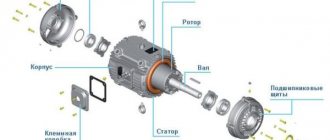
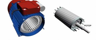
A synchronous generator has two main components: a rotor and a stator.
The rotor (the moving, rotating part of the machine) forms a system of rotating electromagnets powered by direct current from an external source.
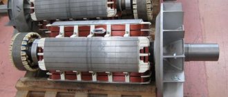
According to their design, rotors are distinguished between salient-pole (Fig. 5-25, a) and non-salient-pole (Fig. 5-25, b). The number of pairs of rotor poles is determined by the speed of its rotation. At a frequency of the generated EMF of 50 Hz, the non-salient pole rotor of a high-speed machine—turbogenerator, rotating at a speed
3000 rpm, has one pair of poles, while the salient pole rotor of a low-speed hydrogenerator (the rotation speed of which is determined by the height of the water pressure), rotating at a speed of 50 to 750 rpm, has a number of pole pairs, respectively, from 60 to 4.
Low-power synchronous generators (up to 100 kVA), as a rule, are self-excited: the excitation winding is powered by rectified current from the same generator (Fig. 5-26). The excitation circuit is formed by current transformers connected to the load circuit of the generator, a semiconductor rectifier PV, assembled, for example, according to a three-phase bridge circuit, and the excitation winding of the OB generator with an adjustable rheostat R.
Self-excitation of the generator occurs as follows. At the moment of starting the generator, due to residual induction in the magnetic system, weak EMF and currents appear in the working winding of the generator. This leads to the appearance of an EMF in the secondary windings of the CT transformers and a small current in the excitation circuit, which enhances the induction of the magnetic field of the machine. The emf of the generator increases until the magnetic system of the machine is completely excited.
For example, in low-speed hydraulic turbines rotating at a speed of 150 rpm. to regulate the frequency, the number of poles of synchronous generators is increased to 40. At diesel power plants, at rotation speeds of 750 rpm, the optimal number of poles is 8.
Device
The design of synchronous generators uses two main working parts - a rotating rotor and a stationary stator. Permanent magnets or field windings are located on the rotor shaft. Magnets have a toothed shape, with opposite poles.
Brushless generators.
The stator windings are placed in such a way that their cores coincide with the protrusions of the magnetic poles of the rotor, or with the cores of the rotor coils. The number of magnet teeth usually does not exceed 6. With this design, the generated current is removed directly from the stator windings. In other words, the stator acts as an armature.
In principle, permanent magnets can be placed on the stator, and the working windings, in which the EMF will be induced, can be placed on the rotor. This will not change the performance of the generator, but it will require rings and brushes to relieve voltage from the armature windings, and this is most often not rational.
A schematic representation of a brushless generator without field windings is shown in Fig. 1.
Rice. 1. Model of a generator with a magnetic rotor
Explanation:
- device diagram;
- diagram of the location of the magnetic poles on the anchor. Here, the letters NS denote a coaxial magnet with poles, and the letter R denotes the steel magnetic core of the rotor in the form of claw-shaped tips.
- cutaway model of the generator. The terminals of the stator phase windings are connected in a star.
Synchronous machines with inductors.
Note that permanent magnets are used as a rotor in low-power alternators. In powerful electrical machines, inductor windings with independent excitation are always used. The independent power source is a low-power DC generator mounted on the shaft of a synchronous motor.
There are designs of low and medium power synchronous generators with self-exciting windings. To excite the inductor, the rectified current of the phase windings is supplied through brushes to the rings located on the stator shaft. The structure of such an alternator is shown in Fig. 2.
Rice. 2. Structure of a medium power synchronous generator
Pay attention to the presence of brushes that are supplied with power from an independent source.
According to the number of phases, synchronous generators are divided into:
- single-phase;
- two-phase;
- three-phase.
Based on the design of the rotor, generators with salient and non-salient poles can be distinguished. The non-salient pole rotor has no protrusions, and the armature wire coils are hidden in the stator slots.
According to the method of connecting the phase windings, three-phase generators are distinguished:
- connected via Tesla's six-wire system (not found practical application);
- "star";
- "triangle";
- a combination of six windings connected in the form of one “star” and “triangle”. This compound is also called “Slavyanka”.
The most common connection is a star connection with a neutral wire.
As a rule, turbogenerators are high-speed. The number of pairs of magnetic poles is equal to one. In order for such a generator to generate electric current at a standard frequency f = 50 Hz, it must be rotated at a frequency:
Backup thyristor self-excitation system (STSR)
In the circuits of Fig. 5.1, 5.2, 5.3, due to the presence of slip rings on the rotor, a backup excitation system can be used. Previous systems used a two-machine unit consisting of an asynchronous motor connected to a DC generator. The asynchronous motor received power from its own buses and was common to several generators.
The modern thyristor self-excitation backup system (STSR) uses the principle of thyristor rectification from an isolation transformer, also connected to the station’s own needs system.
The purpose of these systems is to power the rotor winding of a synchronous machine in cases where the main system is out of operation due to a malfunction or maintenance. At power plants, one backup system is installed per group of generators. Many stations continue to use two-machine units powered by their own buses. More advanced is the static STSR system, which is a powerful adjustable direct current source. The system is equipped with all necessary means of protection, control and switching.
EMF of a synchronous generator
As shown above, the magnitude of the EMF induced in the stator winding is quantitatively related to the number of turns of the winding and the rate of change of the magnetic flux:
Moving on to the actual values, the EMF expression can be written as:
where n is the rotation frequency of the generator rotor, Ф is the magnetic flux, c is a constant coefficient.
When a load is connected, the voltage at the generator terminals changes to varying degrees. Thus, increasing the active load does not have a noticeable effect on the voltage. At the same time, inductive and capacitive loads affect the generator output voltage. In the first case, an increase in load demagnetizes the generator and reduces the voltage; in the second, it is biased and the voltage increases. This phenomenon is called anchor reaction.
To ensure stability of the generator output voltage, it is necessary to regulate the magnetic flux. When it is weakened, the machine must be magnetized, and when it is increased, it must be demagnetized. This is done by regulating the current supplied to the excitation winding of the generator rotor.
Electricity is a type of energy that can be transmitted over long distances, converted into mechanical, thermal energy and transformed into light radiation. Electricity is obtained in various ways - chemical, thermal, mechanical, photoelectric.
Operating principle of a synchronous electric generator
Main stages:
A three-phase synchronous generator can operate in generator mode or motor mode. In the first case, the input to the SG is mechanical energy, and the output is electrical. In the second case, the input is electrical energy, and the output is mechanical.
Types of synchronous generators
The specific application area determines which type of synchronous generator to buy.
Manufacturers offer electric generators:
Application areas of synchronous three-phase alternating current generators
An important feature of a synchronous generator is the ability to synchronize with other similar electrical machines. This property allows these machines to be used in industrial power engineering and, when loads increase during rush hour, to connect backup units.
Three-phase generators are used in:
- diesel locomotives with alternating current rectification using semiconductor elements and other transport systems;
- powerful hydro-, thermal power plants, nuclear power plants, mobile power plants;
- hybrid vehicles in order to combine the thrust of internal combustion engines and the power of traction electric motors.
Synchronous three-phase generators can be used as electric motors with a power of more than 50 kW. In this mode, the rotor is connected to a DC source and the stator is connected to a three-phase cable.
In what cases is it necessary to buy and use a synchronous generator?
A synchronous alternating current generator is chosen in the following cases:
- If high demands are placed on the constancy of voltage and current frequency parameters.
- With a high probability of overloads in the transient mode of consumers with reactive power.
- In case of probability of overloads in operating mode, when consumers with both active and reactive power are connected to the generator.
Advantages of using synchronous generators
Advantages of three-phase synchronous generators:
Modern electric generators are manufactured in accordance with international quality and safety standards.
To convert mechanical energy (internal combustion engine, wind engine, turbine) into electrical energy (DC or AC), a generator is needed. The main parts of the generator are a stationary armature (stator) and an inductor (rotor) driven by a primary motor with a high constant speed of rotation, with an excitation winding powered by direct current.
Application
Synchronous alternating current generators have one important feature: they can be synchronized with other similar electrical machines. In this case, the synchronous speeds and EMF of parallel-connected alternators coincide, and the phase shift is zero. This circumstance allows the devices to be used in industrial energy and to connect backup generators when the rated power is exceeded during peak load hours.
Three-phase traction generators are used on diesel locomotives. Alternating currents to power motors are rectified by semiconductor devices. Today, Russia is already producing diesel locomotives based on asynchronous electric motors that do not require current rectification. In braking mode they operate as asynchronous generators.
Synchronous generators are installed on hybrid vehicles in order to combine the thrust of the internal combustion engine and the power of traction electric motors. By developing active power at rated loads, they save expensive fuel.
There are many other applications. For example, mobile mini-power plants, household current generators, like a single-phase motor, etc.
Synchronous generator device
The design of the SG stator is similar to that of the stator of an asynchronous motor. The stator core, in the grooves of which the winding is located, is assembled from 1-2 mm thick electrical steel plates pressed into a package, separated by an insulating varnish film 0.08-0.1 mm thick.
A synchronous generator can produce single-phase or, most often, three-phase alternating current. A load is connected to the stator winding.
Structurally, the stator poles can be protruding (as in low-speed SGs with a rotation speed of no higher than 1000 rpm, rotated by hydraulic turbines), or not clearly expressed (as in high-speed machines).
A synchronous generator is reversible - it can not only generate alternating current (generator mode), but also perform mechanical work (engine mode).
To cool the rotor, the SG design includes impellers on a common shaft with the rotor. Before entering the SG to cool the windings, the air is passed through a filter; if the cooling system is closed, it is additionally cooled in the heat exchanger. In addition to air, hydrogen is also used as a cooling agent due to its lightness.
The ends of the SG windings are brought out to a terminal block, which allows you to connect the windings of a three-phase SG according to a star or delta circuit.
If it is necessary to obtain a sinusoidal voltage at the output, certain requirements are imposed on the shape of the explicit pole pieces, or it is necessary (with implicit poles) to arrange the turns of the rotor winding according to a special law.
The stator has a common operating principle with an asynchronous machine and differs little from it. Its iron is assembled from electrical steel plates separated by insulating layers. The slots house the AC winding. The most common is the three-phase synchronous generator. The winding wires are securely fastened and insulated, since the load is connected through them.
Separation by rotor type
According to the type of rotor device, the generator device is divided into:
- Salient pole - with protruding or pronounced poles. These rotors are used in quiet-running generators whose rotation speed does not exceed 1000 rpm.
- A non-salient pole is a cylindrical shaped rotor that has no salient poles. These armatures come in two-pole and four-pole types.
In the first case, the rotor consists of a crosspiece on which the pole cores or field windings are fixed. Secondly, high-speed units with a speed of 1500 or 3000. The rotor is made in the form of a cylinder of fairly high quality steel with grooves; an excitation winding is installed in them, consisting of individual windings of different widths.
Types of generators
Generators differ in their excitation methods. In autonomous installations in transport, aviation, and ships, self-excitation is used due to residual magnetization. The method is reliable and easy to use. A common option here is to take energy from the stator winding, which passes through a step-down transformer and a semiconductor PCB converter, as a result of which direct current is supplied to the excitation winding through the collector (shown in the figure below - a).
The principle of self-excitation of a synchronous generator
Another circuit also implements self-excitation by supplying alternating current from the stator winding through the rectifying transformer VT and thyristor TP to the excitation winding OB (shown in the figure above - b). The thyristor is automatically controlled by the AVR excitation regulator based on signals from the input of the SG generator through the VT voltage and CT current transformers. The BZ protection unit prevents the formation of increased voltage and overload current on the excitation winding.
Excitation system with additional generator
A non-contact excitation system is also used, where the SG does not have moving contacts for transmitting energy. Brushes with a commutator have only a PV sub-exciter, which powers the post
Non-contact synchronous generator excitation system
with a constant current, winding I of exciter B.
The concept “synchronous” means that the number of revolutions is in direct mathematical dependence on the frequency of the current. This dependence is determined by the formula n = 60*f/p, where:
Excitation structures
Any turbo, hydro, diesel generators, synchronous compensators, motors produced at the moment are equipped with the latest semiconductor structures, such as excitation of synchronous generators. These structures use the method of rectifying three-phase alternating currents of high or industrial frequency exciters or the voltage of the excited unit.
The design of the generator is such that the excitation structures can provide such unit operating parameters as:
- The first stage of excitement, that is, the initial stage.
- Idle work.
- Connecting to the network using precise synchronization or self-synchronization.
- Work in the energy structure with existing loads or overloads.
- The excitation of synchronous devices can be forced according to criteria such as voltage and current, having a specified multiplicity.
- Electric braking of the device.
Main structural elements
The stator design includes a housing, inside of which there is a core, or a package assembled from sheets of electrical steel of a special shape. The quality of the electric current is influenced by such factors as: the integrity of the sheets in the package (they can be solid or composite), the quality and material of the winding. Copper enamel wire is used for winding, and in cheap devices it is possible to replace copper with aluminum.
Rotors are manufactured salient-pole or non-salient-pole.
- Salient pole rotors are designed for synchronous generators operating with internal combustion engines at low speeds of 1500 and 3000 rpm.
- Non-salient pole rotors are in demand in high-speed (more than 3000 rpm) high-power alternating electric current mechanisms. They are usually placed on the same shaft as steam turbines. Such SGs are called “turbogenerators”.
In a synchronous generator operating under load, the stator magnetic field, superimposed on the main rotor magnetic field created by the field winding, weakens or strengthens it. The effect of the magnetizing force of the armature on the magnetic excitation field of the generator rotor is called the armature reaction.
The connection diagram for a synchronous generator is shown in Fig. 1.
A synchronous generator works as follows. The generator rotor is driven by the prime mover at rated speed, which is kept constant by the prime mover's automatic speed controller. The generator is excited by supplying excitation current to the rotor winding.
Promotional offers based on your interests:
In a synchronous generator operating under load, the stator magnetic field, superimposed on the main rotor magnetic field created by the field winding, weakens or strengthens it. The effect of the magnetizing force of the armature on the magnetic excitation field of the generator rotor is called the armature reaction.
The anchor reaction can be transverse or longitudinal. In transverse reaction, the stator field demagnetizes the advancing edge of the poles and magnetizes the running edge of the poles. The longitudinal reaction can be longitudinally demagnetizing or longitudinally magnetizing. In the first case, the magnetic flux of the armature is directed towards the flux of the poles along their axis, in the second case, according to the flux of the poles also along their axis.
The armature reaction depends on the nature of the load and has a great influence on the operation of the synchronous generator. With a purely active load, the armature reaction will be transverse, and with purely inductive and purely capacitive loads, it will be longitudinally demagnetizing and longitudinally magnetizing, respectively. Conventional generators operate on a mixed load, most often inductive and active.
The need to regulate the excitation current is caused by frequent changes in the nature and magnitude of the load.
Independent excitation can be carried out from an external alternating voltage source.
Methods for exciting synchronous generators
In synchronous generators, including hydroelectric generators, the principle of self-excitation has become widespread (Fig. 1.4, a), when the alternating current energy required for excitation is taken from the stator winding of the synchronous generator and through a step-down transformer and a rectifying semiconductor converter PP
converted to DC energy. The principle of self-excitation is based on the fact that the initial excitation of the generator occurs due to the residual magnetism of the machine.
Synchronous generators
form the basis of the electric power industry, since almost all electricity throughout the world is generated through synchronous turbo or hydro generators. Synchronous generators are also widely used as part of stationary and mobile electrical installations or stations complete with diesel and gasoline engines.
- stator is a stationary part consisting of copper windings placed in slots around a core, which is a set of mild steel plates. A single-phase generator has one winding, a three-phase generator has three;
- rotor is a rotating part that includes a mechanism for generating a magnetic field. Household generators usually use a two-pole rotor. The winding is connected to the control unit (AVR) that supplies it via two brush units. The rotor together with the winding make up an inductor.
SG operating modes
Fire safety requirements for electrical installations
The normal operating mode of the SG can be characterized by any number of working periods, of any duration, during which the main parameters do not fall outside the range of acceptable values. In this mode of operation, deviations of the output voltage and frequency are allowed within 4-5% and 2.5% of the rated value, power factors, and the like. Tolerances for deviations are specified by regulatory documents and are determined by the heating of the machines or are guaranteed by the manufacturer.
Household fuel synchronous generator of domestic production, model "Interskol EB-5500" 5.5 kW
Normal operating modes are unacceptable for long-term operation of the device under circumstances such as overexcitation or underexcitation, transition to asynchronous modes, and overloads. The occurrence of such circumstances is influenced by the following deviations in the electrical network:
- uneven phase loading;
- short circuit;
- alternating loads.
It is worth noting that the normal functioning of the mechanism is affected by the electrical network connected to it, in which any malfunction of individual sources of consumption causes distortion of the shape and asymmetry of the electrical signal.
SG capacity diagram
Important! Long-term operation of an energy-generating device is permissible when the current difference in the phases of a turbogenerator is up to 10% and water generators, synchronous compensating machines are up to 15-20%.
Curvature of the sinusoid on the SG can occur due to high-power converters, rectifying devices, and others.
It is necessary to take into account that the normal functioning of synchronous devices is possible only with high-quality operation of the cooling system. Thus, when the cooling agent consumption is more than 70% of the nominal value, a warning alarm should sound indicating that the device needs to be disconnected from the network, otherwise equipment failure may occur. When the coolant flow is reduced by 50%, the device should unload for about two minutes, and then shut down in a maximum of four minutes.
Characteristic features of SG
SGs have the following characteristic features:
- at zero load (no load), when the armature winding is not closed, the dependence of the electromotive force on the excitation currents is set, and the value of the magnetization level of the generator cores is also set;
- the output voltage depends on the load electric currents - this feature is an external characteristic of the SG;
- the adjustment characteristics of a synchronous machine are manifested in the dependence of the exciting electric currents on the load analogues while maintaining the set parameters at the output in automatic mode.
Synchronous generators have found wide application in industry and energy supply, as they have a simple design, an understandable operating principle and can withstand short-term overloads.
For proper operation and repair work on AC SGs, it is necessary to know their operating principle (rotor and magnetic field rotation at the same frequency) and structure. This knowledge will be useful to industrial engineers and energy specialists, as well as ordinary people who use such equipment for domestic purposes.