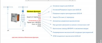
Backup device in case of breaker failure
- home
- Relay protection
- Level of failure
First, let's decipher what the mysterious abbreviation UROV means.
Breaker failure protection means a backup device in the event of switch failure. It is used on high voltage power lines from 35 kV and above. In relay protection, the concepts of short-range and long-range redundancy are used. Let me briefly remind you what it is.
With short-range redundancy, if the protections of a damaged element fail to operate, the damage is eliminated by the action of other protections of this element, and with long-range backup, by the action of protections of adjacent elements.
So the breaker failure rate refers to short-range redundancy. The principle of operation of the breaker protection on the fingers can be explained as follows:
- line B1 switch fails
- with a time delay T* the protection is triggered
* T consists of the time necessary to prevent the flow of short-circuit current during normal operation of the switch (it should be slightly longer than the switch-off time). Or more precisely from the return time of starting protections, relays, reserve time, switch off time taking into account arc extinction, relay scatter time;
- The protection switches off adjacent connections through which the short-circuit point can be fed. In the example, these are switches B2 and B3
- – Redundancy device for failure of 35-500 kV circuit breakers. “Guidelines for relay protection. Issue 6". Already 1966.
- – I.R. Taubes - Redundancy device in case of circuit breaker failure (CBF) in 110-220 kV networks (Electrician's Library, issue 608) - 1988
- – Rubinchik V.A. – Redundancy for shutting down short circuits in electrical networks.
The protection is duplicated by the second set, which reserves the first. The protections are made independently and are powered from different opercurrent circuits through separate CTs and are made with different relays. This is necessary so that the failure of one set of protection does not lead to the shutdown of the second set.
The advantage of breaker failure over long-distance backup is that breaker failure requires fewer shutdowns, which has a positive effect on reliability.
In addition, the breaker failure protection is performed directly on the protection of the element itself, therefore it is highly sensitive.
However, breaker failure circuits are quite complex, since they contain many relay circuits and control circuits for all switches involved in the circuit. Therefore, false alarms are possible, including due to the actions of personnel. Such accidental operations can lead to serious consequences, therefore, serious reliability requirements are imposed on breaker failure protection systems.
More detailed information on typical breaker failure protection circuits and operating principles can be found in the following literature:
AVR in everyday life and at work
Circuit breaker failure backup devices (CBF)
The breaker failure failure is intended to eliminate damage accompanied by failure of the circuit breaker (or circuit breakers). The breaker failure protection must also operate in the event of a short circuit. in the area between remote CTs and the circuit breaker.
Breaker failure protection is used in networks of 110,220,330 kV and above, when, due to the design features of circuit breakers (mainly air and oil circuit breakers with phase-by-phase drives), it is necessary to reckon with their failures to disconnect one, two or even three phases.
The breaker failure protection acts with a short time delay (0.2-0.25 sec for connections 330.750 kV and 0.3-0.35 sec for connections 110-220 kV) to disconnect the connection switches closest to the failed one, ensuring the elimination of the accident with minimal losses for the system .
The following types of breaker failure circuits are used in the power system:
– centralized breaker failure protection for 110-220 kV circuit breakers, which is common to all circuit breakers of the same voltage at the substation;
– individual breaker failure protection for two 330 kV line circuit breakers;
– individual breaker failure protection for each circuit breaker 330-750 kV.
In general, the breaker protection system operates in the following directions:
In the event of a short circuit on one of the connection buses extending from this system (section) and refusal to turn off its circuit breaker - to disconnect this system (section) of buses through
output intermediate relays of selective bodies of differential current protection of this bus system (section).
In the event of a short circuit on the busbars and failure to turn off the bus connecting (sectional) switch, turn off the second undamaged busbar system (section).
If there is a short circuit on the busbars and there is a refusal to turn off the transformer (autotransformer) switch or unit on the side of the buses in question, turn off this transformer (autotransformer) or unit using its switches on the low side, on the power side).
In case of a short circuit on the busbars and failure to turn off the switch of the supply line equipped with high-frequency protection, stop the high-frequency transmitter of the specified line in order to speed up the shutdown of the damage on the opposite side.
For electrical connection diagrams in which there is more than one switch per connection (one-and-a-half, bus-transformer, polygon), the breaker failure operates to disconnect an undamaged element (bus system, line, AT), for which the failed switch is common with the damaged element.
For these schemes, when the protection unit (AT) is operating and the circuit breaker common to the 330 kV overhead line fails, the UROV-330 circuit operates on a 3-phase line shutdown on both sides with TAPV prohibited.
Disabling and prohibiting TAPV on the opposite side of the line is carried out via the tele-shutdown channel. In the same place, disconnection of 3 phases of the line without prohibiting TAPV is carried out from the DFZ after stopping the RF transmitter on the side of the line with a failed switch.
With short circuit on VL-330 and failure of the switch common to the units, the breaker failure circuit acts to disconnect the unit and prohibit the TAPV line.
Prohibition of TAVR is necessary to prevent the supply of voltage to the stopping block in case of successful TAVR of the line.
The TAVR of the opposite side of the line is prohibited via the tele-shutdown channel. When a tele-shutdown channel is taken out of operation, testing of such a line using TAPV CONL should be carried out by power plants.
The backup device is started from all protections of the damaged element, the switch of which has failed.
The breaker failure circuit provides special measures to prevent the device from acting incorrectly to de-energize the bus system (section) in the event of maintenance personnel errors.
SUCH MEASURES ARE:
Installation of an additional voltage trigger common to the bus system (section) that monitors the presence of a short circuit. This body consists of three elements: a negative sequence voltage filter-relay device for action in case of asymmetrical short circuits; a voltage relay connected to phase-to-phase voltage for operation in case of symmetrical short circuits, and a voltage relay connected to zero-sequence voltage for action in case of short circuits to ground.
Automatic check of switch serviceability. The breaker failure circuit is designed in such a way that when a breaker failure fails in any connection, the breaker failure circuit acts without a time delay to turn off the circuit breaker of this connection and, in the event of its failure to turn off (monitoring the presence of current through the switch), the breaker failure with a time delay turns off the circuit breakers of the connections closest to the electrical chains to the failed one.
Consequently, in the event that personnel mistakenly close the starting circuit of any connection, the breaker failure protection device will turn off the switch of only this connection and, since the current through the “failed” switch will stop, the breaker failure protection circuit will return to its original state.
Using duplicate start. The starting circuits of breaker failure protection are duplicated by fixing their action on tripping the circuit breaker. The action of the protection is fixed by the “on” position relay contacts.
The use of a factor confirming the operation of the protection in the breaker failure circuit eliminates the need for automatic testing of the serviceability of the circuit breaker, which reduces the number of false disconnections of connections, for example, when testing individual protections on operating lines, when the breaker failure failure starting circuit from the protection being tested is mistakenly not disconnected by the overlay.
Such schemes are usually used with 110 kV breaker failure protection, put into operation since 1973-1974.
The circuit breaker failure circuit monitors the health of the circuits. The circuit health monitoring circuit puts the breaker failure failure out of action after 0.8 - 1.2 seconds after the appearance of any malfunctions and sends a signal about the malfunction; Removing the signal and putting the breaker failure circuit back into operation is carried out by pressing the button on the breaker failure failure panel.
When operating ROV-330kV and ROV-750kV, prohibiting automatic reclosure of connections disconnected from their operation is prohibited in all cases.
After the operation of the breaker failure protection device (BREV-110, 220 kV breaker failure protection), the automatic reclosure of connections disconnected from the breaker failure protection device is prohibited only when the failed protection switch of transformers (units) is acted upon.
ads
Greatping writes:
1. One eminent relay operator is definitely sure that in addition to Obagley’s remark (kudos to him), the main function is to turn off one circuit breaker, and not half of the substation, in the event of a false start of the breaker failure. there is a second main function - to reserve the failure of protections associated with their erroneous output - the exploded 3xAODTSTN at Arzamas 500 kV is a mute confirmation of this - therefore action on oneself is necessary.
Unfortunately, as scorp correctly noted, the action to disconnect and start the breaker failure protection must be input/output by different switching devices in the protection cabinets. Only then will the breaker circuit breaker be able to reserve the personnel error. But not all projects have such devices in the breaker failure protection circuit. There are cases when the breaker failure circuits as part of the ACU are generally hard-wired, without keys. On the one hand, it’s good, you won’t lose the effect, on the other hand, hemorrhoids during maintenance. In general, you need to look at design decisions very carefully and weigh the pros and cons. And all the difficulties are due to the fact that currently there are no standard projects for URZA based on MP terminals. Nobody wants to do this work and take responsibility.
Greatping writes:
2. Answering the question from the experienced Bogatikov: We had a case in Dagestan when one of the switches of a 330 kV overhead line was turned off solely by the action of the breaker failure on itself. Calculated by chance. And why introduce a delay in the operation of the breaker failure protection system on yourself? Answer: To calculate it at the first shutdown and not by chance.
Do you mean that the delay in the action of the breaker failure protection on itself would help to calculate? Perhaps, but when information passes through dispatch channels that everything is working normally (not a single operative will notice a delay of 100-150 ms), no one carefully analyzes the oscillograms. In this situation, there was an overlap of several factors and the overall picture could only be clarified after connecting the overhead line protection and breaker failure switches to PARMA using analog and discrete signals.
Greatping writes:
4. Setting I< breaker failure, Ic max, t breaker failure are closely related. You can have t LEV < 100ms but then I< LEV should be >0.05 I kzmax. The constant is empirical, I think Obagley can offer a more reasonable value
grsl writes:
The choice of current level for breaker failure is of course related to time t1
This is what I didn’t understand, what is the connection between current and time? More? The time depends on the technical characteristics of the primary and secondary equipment, and the current is selected for AT, T, overhead lines 110, 220 kV based on sensitivity to short circuit. For overhead lines 330 and above - according to detuning from capacitive currents. Ideally, the breaker failure protection system should include capacitive compensation. This condition is fulfilled only by PDE-2005 and SHE2710 511. In the last settings that we issued for the breaker failure protection in S60, we generally had to sacrifice sensitivity to short circuit on the LV AT side for the sake of detuning from the capacity of a 500 kV overhead line (more than 400 km). At the same time, as part of the main AT protections, it was necessary to install an analogue of the LV breaker failure with start-up from the main AT protections, control of the HV current and the on position of the HV switches.
grsl writes:
so the minimum time settings: t1>tcb+tv+tmargin=40ms+19ms+20ms>79ms
Why do you need to incur such difficulties in Urov?
grsl writes:
1. Level of failure from no-current protection (for example, gas protection, or reverse power protection of a generator); what will be the current settings?
For gas, none, because it reacts to turn faults, and this is not the design mode. What is reverse generator power?
grsl writes:
2. Start the breaker failure protection - and at what constant should we do the boom? 3. What is the permanent position of the AUV?
What do you mean, power supply via operational circuits?
grsl writes:
4. Why is the breaker failure level at 150ms if the system can’t handle 200-250ms?
Of course he does. But a calculation is a calculation. If he allows it, why wait longer? For four years with such settings, there was not a single hint of improper operation. I'll knock on the wooden head. On the other hand, if you believe the calculations of the regime operators, during a short circuit at a nuclear power plant outdoor switchgear, the stability of the units is disrupted after 100 ms. In this case, a reasonable reduction in breaker failure time is justified.
Operating experience of breaker failure protection - Redundancy device in case of circuit breaker failure (breaker failure failure) in 110-220 kV networks
| Close reservation |
| Principles for constructing a breaker protection system |
| Breaker failure protection circuits |
| Busbar system damage with transformer breaker failure |
| Breaker failure for a quadrangle circuit with control of current flow through the switch |
| Breaker failure for a bridge circuit with three switches |
| Breaker failure for a dual bus system with voltage control |
| Breaker failure for a switchgear circuit with a double bus system with current monitoring in the circuit of each connection |
| Breaker failure for a bridge circuit with three switches with current control |
| Selecting settings |
| Breaker failure failure adjustment |
| Operation of breaker protection system by operating personnel |
| Experience in operating a breaker protection system |
| Bibliography |
Page 15 of 16
7. OPERATING EXPERIENCE Operating practice, analysis of incorrect cases, assessment of the behavior of the breaker failure failure in various modes and specific situations made it possible to identify a number of its features and shortcomings. Some measures to change the circuit, its individual components, methods for selecting settings and modes, developed or applied in power systems, on the experience of which the author relies, have increased the reliability of the breaker failure protection system. Some of the proposals given below are quite simple, and their implementation does not require significant difficulty, others require certain costs, their implementation is not always advisable and can only be recommended when carrying out work on the reconstruction of a substation, replacing a breaker circuit breaker with the installation of panels on site, etc.
1. A breaker failure failure with a voltage monitoring signal, as noted above, has a significant number of shortcomings; its sensitivity in many cases is insufficient, therefore the power system is taking measures to replace all the circuits in question in operation with modern ones. However, such work under operating conditions requires significant labor costs and a large amount of cable. Therefore, it is advisable to introduce as a temporary solution. additional elements in the circuit To increase sensitivity in case of damage behind transformers or on lines. To do this, additional voltage relays RNF-1M, RNN-57 and RN-54/160 are connected to the voltage transformers on the sides of the power transformers opposite to the buses under consideration according to the diagram in Fig. 10, b. If the relays are connected to voltage transformers (VT) of a 6-35 kV network operating with an isolated neutral, the RNN-57 relay, usually connected to an open delta circuit, is not included in the circuit. In 6-10 kV networks, where in many cases there is a VT between the power transformer and the switch, it is advisable to include a voltage relay on the circuit of this VT. For three-winding power transformers, you can limit yourself to installing additional relays on only one of the opposite sides while ensuring the sensitivity of these relays at least in the case of incomplete-phase short circuits behind the transformer, giving preference to connecting the relays to a 6-10 kV voltage transformer. The relay settings are selected similarly to the selection of the settings of the main relays of the breaker failure circuit. The contacts of additional relays RN-54 through additional pads are connected in parallel with the breaking contact KV24 and the pad SX45 (see Fig. 10, d). To increase the sensitivity of the breaker failure failure in the event of a line switch failure in ground fault modes, the opening contact of the RT-40 current relay of the third or fourth stage of line protection is connected in series with the winding of the KV24 or KV25 voltage relay (see Fig. 10, b). The choice of the third or fourth stage current relay setting is determined by the required sensitivity at the end of a given line or in the redundancy zone. It is advisable to use the relay contact of the most sensitive protection stage. If the sensitivity of the breaker failure relay is not ensured in case of faults at the end of several lines, then the sequentially breaking contacts of the current protection relays of several lines are switched on. It is possible to increase the sensitivity of such a breaker failure circuit during phase-to-phase short circuits by connecting an additional two current relays per connection, connected to the currents of two phases with settings adjusted from the load currents. It is obvious that the inclusion of additional current relays complicates the circuit and reduces the reliability of the breaker failure failure.
2. In many cases, relays of the RP-251, RP-258 series are used for output protection relays. These relays are used to provide an operating time of 0.07-0.1 s. To satisfy this condition, copper sleeves are installed on the RP-251 relay, and short-circuited windings are installed on the RP-258. At the same time, the time delay for the return of these relays is not regulated, but depending on the gap between the valve and the core in the actuated state, it can reach 0.5-1 s. In this case, the protection return time increases sharply and can no longer be a quality that ensures the failure of the breaker failure during normal disconnection of the circuit breaker after a short circuit and protection operation. Therefore, when checking output relays of type RP-251 and RP-258, enterprises are asked to check its return time simultaneously with checking the response time. This time should be no more than 0.1 s. Such checking and, if necessary, adjustment does not cause difficulties. Even more correct (but also more complex) is the following solution. In parallel with the winding of the output relay RP-250, the winding of the relay RP-23 is turned on. In the breaker failure starting circuit, the closing contacts of both relays are connected in series. The circuit is closed after both relays are activated and simultaneously with the formation of a circuit to open the circuit breaker by the contacts of the RP-250 relay. The circuit will open after the responsive protection elements return and the armature of the RP-23 relay falls off. Accordingly, the operating time of the breaker failure failure can be reduced.
3. The long-term permissible current of the RNT-560 and DZT-10 relays is 10 A (in relation to windings intended for operation in single-ampere transformer circuits, the permissible current may be less than twice the rated one and must be checked each time for compliance with the operating current). Such a large value of the long-term current is explained by the fact that the relay is connected to the differential protection circuit of transformers, where the CTs are connected in a triangle and where, at the rated current flowing through the CT, the current in the relay is 5у/3 = 8.6 A. In real long-term power overloads transformers, the current in the relay can approach 10 A. At the same time, the same circuits (see Fig. 8, b; 10, c) include current relays for the RT-40/R breaker failure circuit, the long-term permissible current of which in accordance with the technical data is only 1.1 rated value or 5.5 A for a relay with a rated current of 5 A. This situation leads to the need to overestimate the transformation ratios of current transformers so that the current in the RT-40/R relay at rated load and real long-term overloads of power transformers did not exceed the permissible current for the relay of 5.5 A. In a number of cases, the need to fulfill this requirement causes unjustified difficulties. During subsequent reprocessing of the relay, the manufacturer must increase its long-term permissible current to twice the rated current.
4. There was a case of failure to operate the serviceability monitoring of the breaker failure circuit according to Fig. 6. After the contact of relay KT4 is closed, relay KL36 begins to operate. Naturally, contact KL36.2 opens first, and only then contact KL36.1 closes. When KL36.2 opens, the KT4 winding is de-energized and, if the time difference in the closing of KL36.1 and the opening of KL36.2 is greater than the time of opening the KT4 contact, the KL36 relay will not operate and self-hold. The set of time delay KT4 will begin again. The alarm circuit will be triggered multiple times, but the breaker failure failure will remain operational. To eliminate the defect, it is advisable to connect a spark-extinguishing circuit in parallel to the KT4 winding, consisting of two series-connected diodes of the D226 type (instead of an active-capacitive circuit or a varistor). In this case, the time delay for opening the KT4 contact reaches 0.1–0.13 s and, thus, the possibility of a defect manifestation is eliminated.
5. In accordance with standard solutions, the automatic reclosure of busbars is prohibited after the breaker failure failover operation is carried out if the reasons for the breaker failure failure operation were damage to the transformer, the operation of its protections and the failure of the circuit breaker. It is easy to reconstruct the circuit in such a way that the automatic reclosure of busbars is prohibited when a breaker failure occurs for any reason. Thus, in a modern standard circuit for a double bus system with a fixed connection of elements, it is enough to bypass the relay contacts KL1.2 and KL4.2 (see Fig. 6, b) in order to ensure the prohibition of automatic reclosure after operation of the breaker failure failure in the event of failure of not only the transformer switch, but and line switch. Slightly more complex modifications are known that ensure the prohibition of automatic reclosure when the breaker failure protection is operating in all modes. However, standard schemes provide for the prohibition of autorecloser of busbars only when transformer protections are operating, and there are no official recommendations for prohibiting autorecloser of busbars when operating a breaker failure protection system in the event of any circuit breaker failure. At the same time, a number of power systems apply such solutions taking into account the following: a) the cause of breaker failure can be not only a malfunction of the drive or shutdown circuits, but also damage to the breaker, unsatisfactory operation of power contacts, when repeated shutdown due to unrepaired damage can lead to serious damage; b) unsuccessful automatic reclosure of buses after turning on one of the lines and failure of the line switch of the damaged line and the operation of the breaker failure leads to an off-design mode of operation of the protection, when the short-circuit current is determined only by the power system with one supply connection. In such a minimum mode, both the main protection of the damaged line and its backup protection may fail, and, naturally, the breaker failure failure will not work either. The first stages of protection may fail in sensitivity or current of precise operation, and the damage will be turned off by the last stages of protection with long time delays; In the event of a failure due to insufficient sensitivity of the protection of the damaged line and the lack of long-range backup along the line switched on from the automatic reclosure, a long-term short circuit with serious consequences may form. In addition, in this mode, the currents in the damaged and supply lines are equal; with sufficient sensitivity, it is possible to violate the selectivity of the protection of the lines in question and, as a result, disconnect the line that was switched on from the autorecloser buses on the opposite side with the disconnection of the tap substations connected to it; c) in the event of a non-full-phase failure of the circuit breaker, after successful automatic reclosure of the busbars, a non-full-phase mode is created with corresponding consequences. In this case, the prohibition of automatic reclosing in the DPS circuit will not work. From the above it follows that in those cases when automatic reclosure of busbars is allowed upon failure of a linear circuit breaker, it is necessary to check the behavior of the protections in the considered modes.
6. When implementing breaker failure protection at substations with transformers with one-way power supply, the question arises about the advisability of putting into operation circuits for starting breaker failure failure in the event of a short circuit on the buses and failure to disconnect the transformer switch on the supply side. It would seem that there is no need for this circuit, but it is considered advisable to keep it in operation, since the possibility of parallel operation on the low voltage side of the distribution network of a given substation, including networks of a lower voltage stage, can never be excluded. Controlling the inadmissibility of parallel work is practically impossible. In this case, maintaining the considered breaker failure starting circuit ensures its operation and disconnection of the power source from the low or medium voltage side of the transformer.
7. It is known that modern transverse differential protection schemes [14] are designed in such a way that when the first line is turned off, only the relay winding circuit is automatically broken, and when it is triggered, the second line is turned off. Thus, during external short circuits, the output protection relay may be unnecessarily triggered, acting to disconnect the first line and start the breaker failure. The failure of the breaker failure protection in this case is determined only by the open contacts of the de-energized current relays of this line. Similarly, when the total protection of parallel lines connected to different bus systems of a given substation is triggered, with the failure of the circuit breaker of one of the lines, the failure of the breaker failure to trip the second bus system also depends on the reliable return of the current relays of the second line.
The decrease in reliability for failure in the considered cases has led to the fact that in some power systems, the start-up of breaker failure protection from the total protection of lines connected to different bus systems, as well as from transverse differential protection, is not carried out. It seems that such a decision cannot be considered correct. To increase the reliability of the operation of the breaker failure protection system with the above protections, it is advisable to turn on the contact of the additional current relay RT-40/R in series with the contact of this protection acting on the start-up of the breaker failure failure. According to the current circuits, an additional relay is switched on at the CT of the corresponding overhead line, which was not used to connect two current relays according to standard diagrams.
8. Let us consider once again the effect of a breaker failure failure during a short circuit on the buses and a failure of the busbar using the example of the circuit in Fig. 6. In addition to the bus protection contacts, current monitoring relays and the opening contact of the ON position relay, when the breaker failure is operating (short circuit on the first bus system), the time relay winding KT2, its contacts KT2.2, the relay winding KL8 and its contacts KL8.1 and KL8.2, relay coil KL25 and relay contact KL25.1, i.e. three relays and five contacts work. To form the necessary circuits, it is necessary to use cable connections to enter the current relay contacts and the ShSV ON position relay into the breaker failure circuit, as well as the impact of the breaker failure on the busbar protection - a total of four cable cores.
Rice. 15. Breaker failure level of bus coupling switch
It is proposed to reconstruct the circuit as follows. Relay KL8 and output circuits acting on the DZSh, associated with the participation of contact KL8.2, are excluded from the breaker failure circuit. The KA and KQC ShSV relay contacts are not included in the circuit. In this case, it is taken into account (this was noted earlier) that the ShSV protections, as a rule, are not normally introduced and do not affect the start-up of the breaker failure protection. An additional time relay KTD0$ (Fig. 15) and an indicator relay USYAdod are mounted on the bus protection panel. When the conditions for actuation of the contacts of the output relays of the DZSh of the first or second bus system are combined in the presence of current through the shsv and a command to turn off the shsv (KQC relay contact is closed), the ATdob relay is triggered, after a specified time of operation of the breaker failure, the indicator relay Kntsob (operation of shsv level) and the violation relay are activated fixation in the DZSh circuit, which, provided that the DZSh is triggered in the initial mode with the effect of disabling one of the bus systems, will lead to the activation of the DZSh output relays, which also disconnects the second bus system. Please note that with the considered action of the breaker failure, the operation of only one time relay, one intermediate relay and only two contacts is required. To create a circuit, only two cable cores are required to output the ShSV circuits to the DZSh panel. Moreover, with this design of the circuit, it is possible to eliminate the contact of the ON position relay. Even if a circuit is formed falsely to trigger the ATDOB relay, consumers will not be disconnected, and the resulting activation of the relay for violating the fixation of the DZSh circuit does not pose a danger. The exclusion of some circuits in the main circuit breaker failure circuit increases its reliability, simplifies its logical circuit, and facilitates testing of the circuit.
9. For breaker failure circuits with a double bus system and a fixed connection of connections (see, for example, Fig. 6), the breaker failure failure starting circuits from transformers differ from the starting circuits when lines are damaged. A separate intermediate relay is installed in the breaker failure protection starting circuits from each transformer (KL1 for 77 and KL2 for T2). In the event of damage to the busbars and failure of the transformer switch, the breaker failure protection acts on the output relays of the transformer and turns it off on the sides opposite to the damaged busbars. In this case, in the breaker failure circuit, in addition to the contacts of the current control relay and the ON position relay of the switch, one time relay, two intermediate relays and five contacts operate. In the circuits under consideration, four cable cores are used - two for introducing current relay and KQC relay contacts into the breaker failure circuit, and two for forming an output circuit for the influence of the breaker failure on the output relays of the transformer. When the transformer operates through a bypass switch, the number of relays and contacts participating in the operation of the breaker failure increases.
It is proposed to carry out the following reconstruction. The circuits for starting the breaker failure failure in the event of a fault in the transformer are carried out in the same way as for lines, without installing separate intermediate relays for each transformer. The output circuits of the breaker failure protection operating on the output relays of the transformers are taken out of action. In this case, the breaker failure circuit is simplified, the number of output circuits is reduced, and the effect of the breaker failure in case of damage on the line or in the transformer becomes the same.
To turn off the transformer in the event of damage to the busbars and failure of the circuit breaker, one of the following schemes is performed: a) if the transformer protections have an operational acceleration circuit, backup protections at the output of the busbar protection (Fig. 16, a) acting on the output relays with a time of 0.5 s , in parallel with the normally disconnected pad SX, the contact of the output relay DZSh from the corresponding bus system is switched on (KL - contact of the transformer protection relay); Rice. Fig. 16. Breaker failure of transformers during a short circuit on the busbars: KL - contact of the repeater of the starting elements of backup protection Fig. 17. Addition to the DZSh, providing redundancy functions in case of short circuit on the busbars and failure of the line breaker
b) in the absence of operational acceleration circuits, an accelerated shutdown circuit of the transformer is installed with a time of 0.5 s under the action of the DZSh (Fig. 16, b). In both considered cases, the number of active relays and contacts is sharply reduced, however, additional circuits have to be implemented in the bus protection circuit; c) when installing two-winding transformers with double-sided power supply at a substation, during the operation of the DZSh, both transformer switches are switched off; in this case, the failure of the switch can be ignored. 10. When reconstructing the circuit according to the two previous proposals, it is advisable to “free” the breaker failure protection from one more function - stopping the HF transmitters of the DFZ-201 line protections during a short circuit on the buses. For this purpose, corresponding circuits are made in the busbar protection circuit (Fig. 17). In this case, bus protection contacts, time relays, and a number of output relays can be excluded from the breaker failure circuit. The basic circuit breaker failure circuit is further simplified.
"Previous article page - Next article page"