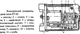
Purpose and types
A current control relay is a device that reacts to sudden changes in the amount of incoming electrical current and, if necessary, turns off the power to a specific consumer or the entire power supply system. Its operating principle is based on comparing external electrical signals and instantly responding if they do not coincide with the operating parameters of the device. Used to operate a generator, pump, car engine, machine tools, household appliances and more.
Photo – OptiDin OM-110
There are the following types of direct and alternating current devices:
- Intermediate;
- Protective;
- Measuring;
- Pressure;
- Time.
An intermediate device or maximum current relay (RTM, RST 11M, RS-80M, REO-401) is used to open or close circuits of a certain electrical network when a certain current value is reached. Most often used in apartments or houses to increase the protection of household equipment from surges in voltage and current.
Photo - diagram of RTZ - 50
The operating principle of a thermal or protective device is based on monitoring the temperature of the contacts of a specific device. It is used to protect devices from overheating. For example, if the iron overheats, such a sensor will automatically turn off the power and turn it on after the device has cooled down.
Photo - RST-80AV
A static or measuring relay (REV) helps close the contacts of the circuit when a certain value of electric current appears. Its main purpose is to compare the existing network parameters and the required ones, as well as quickly respond to their changes.
Pressure switches (RPI-15, 20, RPZh-1M, FQS-U, FLU and others) are necessary for monitoring liquids (water, oil, petroleum), air, etc. Used to turn off the pump or other equipment when the set values are reached pressure. Often used in plumbing systems and at car service stations.
Time delay relays (manufactured by EPL, Danfoss, as well as PTB models) are necessary to control and slow down the response of certain devices when a current leak is detected or other problems in the network. Such relay protection devices are used both in everyday life and in industry. They prevent premature activation of emergency mode, operation of RCDs (also known as differential relays) and circuit breakers. Their installation scheme is often combined with the principle of including protective equipment and differentials in the network.
In addition to these, there are also electromagnetic voltage and current relays, mechanical, solid state, etc.
A solid-state relay is a single-phase device for switching high currents (from 250 A), providing galvanic protection and isolation of electrical circuits. These are, in most cases, electronic equipment designed to quickly and accurately respond to network problems. Another advantage is that such a current relay can be made with your own hands.
By design, relays are classified into mechanical and electromagnetic, and now, as mentioned above, into electronic. Mechanical can be used in various operating conditions, its connection does not require a complex circuit, it is durable and reliable. But at the same time, it is not accurate enough. Therefore, now its more modern electronic analogues are mainly used.
Photo - RT85
Power relay
July 30, 2022 — 9:03
Power relays in most cases determine where exactly an emergency or some kind of inconsistency occurred. But if you make a more accurate assessment of whether the power direction relay is working correctly, it is much more convenient to use the torque formula, which is expressed in terms of the voltage that is supplied to the device.
In order for the device to work correctly, it is necessary that the voltage supplied to it be greater than Ucvmin.
It will be on when there are asymmetrical short circuits. The dead zone is based on a small medium, but it appears only in metallic three-phase faults.
Secondary flows are measured when directional protections are checked, as well as unbalance currents in the neutral wires and in the working windings of differential protections.
Then they look at the correct connection of the voltage circuits to the device by removing vector diagrams. At the same time, when phasor diagrams are taken, the zones in which the power direction relays operate are also checked, and it is the choice of the direction of the power relays of directional protections that can be checked.
Finally, power direction relays (PM) can also be used, for example, in a wide variety of protection devices to sense power.
Structure:
This device has two windings. The first has a connection to the CT, and is also enveloped in a secondary current Iр, while the second has a connection to the VT and is enveloped in a current that is directly proportional to the voltage that is at the terminals (Uр).
These two currents have their own different flows. They are proportional to different currents (the first is Ip, the second is Uр), in this situation the direction of the power, that is, the sign of the rotating torque, directly determines the direction of this power.
Power limit relay
With this device you can:
- Firstly, to protect the buyer from some low-quality parts in the electrical network;
- Secondly, it is also used to turn off the load, when the power being used goes beyond the norm, for a certain period of time;
- Thirdly, it is used when the load is not completely turned off, when the voltage goes beyond the norm for a certain period of time;
- It is also used at zero voltage, reverse voltage, and also in a tense sequence;
- When a very high power load is used;
- Also used to warn of possible emergency situations;
- They are also used when the load is connected remotely to the interface;
- This device can support loads that exceed 2.5 kW and they also support loads up to 30 kW.
- Also, with not very high-quality voltage, characteristic of this situation are very large voltage surges, distortion, and violation of the sequence;
- If you exceed the permissible current limit, that is, exceed the maximum, you increase the load too much.
Power limiting relay OM-110 Power limiting relay OM-110 is used to monitor the active or total power of a single-phase load. Range,
which can be measured: from 0 to 20 kW also possible from 0 to 20 kVA.
OM-110 capabilities: disables some downloads, if the download level increases excessively, then automatically turns it on.
You can see that on the front of the device there are special potentiometers, as well as dip switches, with the help of which a person can quickly understand:
- First is the maximum power level;
- Secondly, this is the response time;
- Thirdly, this is also the automatic reclosure delay time.
The power it consumes is measured without connecting the electrical circuit; a special current sensor is used, which is built into the device itself.
The OM-110 model can be used, for example, as a digital wattmeter, that is, as a device that measures both active and linear power.
It can also be used as a device for limiting power consumption.
The OM-110 is powered from voltage measurement circuits.
Design and operating principle
The DC relay consists of the following elements:
- Electromagnet;
- Contacts;
- Anchors;
- Springs;
- Branches for connection to the network.
When the regulator is connected to the network, the coil begins to receive electrical energy. After this, the armature is attracted to the metal core and the contacts fly over. At the same time, the contacts of the devices connected to the relay circuit close. Moreover, if electric current is not supplied (for example, in the absence of electricity) or is supplied, but unevenly (surges are observed in the network), then the contacts of the connected devices are pulled upward, after which the circuit opens.
Photo - drawing
The effect may vary depending on the design and purpose of the device. For example, solid-state relays (SSR) of the KIPPRIBOR type contain additional power switches based on triacs and thyristors in their design, which increases their efficiency. Separately, it is necessary to note the throughput, because there are devices designed for low and high currents.
Photo - design
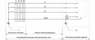
Graphic symbols in electrical diagrams
Regarding graphic symbols in electrical circuits, GOST 2.702-2011 refers to three other GOSTs:
- GOST 2.709-89 “ESKD. Conventional designations of wires and contact connections of electrical elements, equipment and sections of circuits in electrical circuits.”
- GOST 2.721-74 “ESKD. Conditional graphic designations in schemes. Designations for general use"
- GOST 2.755-87 “ESKD. Conventional graphic symbols in electrical diagrams. Switching and contact connection devices."
Conventional graphic symbols (UGO) of automatic circuit breakers, switches, contactors, thermal relays and other switching equipment that is used in single-line diagrams of electrical panels are defined in GOST 2.755-87.
However, there is no designation for RCDs and difavtomats in GOST. I think it will soon be reissued and the RCD designation will be added. In the meantime, each designer depicts an RCD according to his own taste, especially since GOST 2.702-2011 provides for this. It is enough to provide the UGO designation and its explanation in the explanations of the diagram.
In addition to GOST 2.755-87, to complete the circuit, you will need to use images from GOST 2.721-74 (mainly for secondary circuits).
All designations of switching devices are based on four basic images:
using nine functional features:
Basic graphic symbols used in single-line diagrams of electrical panels:
| Name | Image |
| Circuit breaker (automatic) | |
| Load switch (switch) | |
| Contactor contact | |
| Thermal relay | |
| RCD | |
| Differential automatic | |
| Fuse | |
| Automatic switch for motor protection (circuit breaker with built-in thermal relay) | |
| Load switch with fuse (switch with fuse) | |
| Current transformer | |
| Voltage transformer | |
| Electric energy meter | |
| A frequency converter | |
| Normally closed contact of push-button switch with automatic opening and return of the control element | |
| Normally closed contact of a push-button switch with opening and return of the control element by pressing the button a second time | |
| Normally closed contact of a push-button switch with opening and return of the control element by pulling the button | |
| Normally closed contact of a push-button switch with opening and return of the control element via a separate drive (for example, pressing a reset button) | |
| Normally closed contact with delay when activated | |
| Normally closed contact with delay during return | |
| Normally closed contact with delay during operation and return | |
| Normally closed contact with delay when activated | |
| Normally closed contact with delay during return | |
| Normally closed contact with delay during operation and return | |
| Contactor coil, general designation for relay coil | |
| Impulse relay coil | |
| Photo relay coil | |
| Timing relay coil | |
| Motor drive | |
| Lighting lamp, light indication (light bulb) | |
| A heating element | |
| Plug connection (socket): socket pin | |
| Arrester | |
| Surge suppressor (SPD), varistor | |
| Dismountable connection (terminal) | |
| Ammeter | |
| Voltmeter | |
| Wattmeter | |
| Frequency meter |
The designations of wires and busbars in electrical panels are determined by GOST 2.721-74.
Specifications
Choosing a relay is a rather serious task, for which it is very important to choose the most suitable device. Let's consider the description and parameters of several popular devices of domestic and foreign production.
RP 8 – intermediate model, included only for temporary control, not used for permanent monitoring. Affordable and easy to use.
| Current, A | 8 |
| Voltage, V | 24 |
| Disconnection Un, V | 0,7 |
| Climate | –20 +40° С |
| Durability, number of operations | 1 million |
| Resistance, Ohm | 92 |
| Response time, sec | 0,6 |
SG/C-1RW is a calorimetric single-phase fan relay for air flow control. The instruction manual also states that they can be used in air conditioning systems.
| Current, A | 6 |
| Voltage, kV | 1,5 |
| Flow change, m/s | 0,1–30 |
| Temperature gradient, degrees | 15 |
| Working pressure, bar | 10 |
| Protection | IP67 |
Neutral small-sized current relays are most often used in railway transport; consider the characteristics of the NMShM1-1000/560 model for 24 V and operation parameters of 45.
| Winding | Copper |
| Coil resistance, Ohm | 1000/560 |
| Overload, V | 45 V |
| Voltage, V | 24 |
RTD is a bistable device that is used in emergency support systems; they operate on both direct and alternating electricity. The main difference is that the device can be used to be connected to the network during increased vibrations and even seismological activity. RTD 11:
| Voltage, V | 40 |
| Current, A | 0,05 |
| Response time, s | 0,1 |
| Wear resistance, million | 4 |
| Operation error, % | 10 |
Separately, it should be said about the three-phase maximum current relay RT40, which is used in emergency networks as an indirect device. RT40/2:
| Current settings, A | 0,5…2,0 |
| Triggering, A | 0,5…1,0 |
| Wear resistance | 40 million |
| Voltage, V | 24 |
| Climatic performance | UHL |
RTF-8 – reverse action or sequence relay. Designation:
- R – relay;
- T – current;
- F – filter.
| Current, A | 1–5 |
| Voltage, V | 220 |
| frequency Hz | 50 |
| Operating temperatures, degrees | -10 to +40 |
| Wear resistance, million cycles | 1,5 |
Air flow sensor-relay DRPV-1:
| Flow speed, m/sec | from 4.0 to 10 |
| Air duct cross-section, mm | 150x180 |
| Explosion protection | 1ExdIIBT4 |
| Output signal | 0.05 to 0.5 A |
| Environmental parameters | from - 10 to + 50 98% at a temperature of 35°C |
| Overall dimensions, mm | 276x143x248 |
Video: current control relay
File archive ›› Unified frequency relay URCH-3M. Manual
The URCH-3M relay is intended for use in emergency automatic circuits for limiting frequency reduction (system AChR-CHAPV, CHAVR, DARS, AChRS), blocking AChR1 by frequency reduction rate (FRS) when the motor load runs out, frequency increase control systems, as well as frequency dividing automation (CHDA). The URCH-3M relay is a modernized analogue of the URCH-3 relay, has an internal electromagnetic shield, is resistant to industrial frequency magnetic fields in accordance with IEC-1000-4-8-93, noise immunity complies with IEC 225-22-1. The URCh relay includes 3 independent relays for monitoring frequency decrease and increase (3 channels) with a separate time delay for operation and return of each, provides the ability to jointly set the AFC and FFA settings (2 settings on each channel, a total of 6 frequency settings and 6 time settings on the URCH relay). One URCH-3M relay provides a replacement for three frequency relays of the RF-1, RF-2, RSG-11 types produced by JSC ChEAZ, as well as three to six time relays.