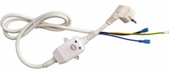
What is an RCD?
RCD (residual current device)
is a switching device for protecting an electrical circuit from leakage currents. Unlike a circuit breaker, which protects wiring from short circuits and significant overloads, this device only operates when leakage currents occur.
Leaks
in a household electrical network may be associated with human contact with conductive elements (for example, in an electrical appliance, socket) and metal casings of devices exposed to voltage due to damage.
They can also be caused by a violation of the electrical wiring insulation, including due to heating due to incorrectly calculated load and poor-quality installation. Relatively small leakage currents can lead to serious consequences. In the first case, this can cause an electric shock to a person, in the second, it can cause a fire in the wiring. The protective shutdown device, when a leak occurs above the limit set for it, allows you in a split second
and thereby prevent electric shock to a person or avoid a fire. To protect against electric shock, devices are used that are triggered by differential currents (leakage currents) above values of 6, 10, 30 mA:
- For a private house or apartment, choose an RCD with a value of 30 mA
(for groups of sockets or lighting). - RCCBs with differential currents of 6 and 10 mA
are used to protect individual consumers (for example, a washing machine, dishwasher, etc.) and premises with increased danger.
For fire protection in case of possible insulation failures in the electrical wiring, residual current switches with values of 100, 300 and 500 mA are used.
Equipment selection criteria
Existing RCDs are divided into single-phase and three-phase. Only the first devices are used in everyday life. A single-phase line almost always goes to an apartment or a private house from the electrical panel. For this purpose, a differential switch is used with two terminals (input plus output), whereas three-phase analogues have four terminals for wires.
All RCDs are divided according to the type of leakage current into three groups: “A”, “B” and “AC”. For fire-fighting needs, you should take the “AC” option (only for alternating current), “A” and “B” are more expensive, as they are additionally designed to work with pulsating and rectified currents
Residual current devices are:
- electronic;
- electromechanical.
The former are more expensive, but less reliable. In almost all cases, it is best to take a fire protection RCD of the electromechanical class. This switch does not require external power. If the supply line breaks, the electronic analog stops working and monitors for insulation damage. Plus, during a power surge, its response time increases.
The two main criteria for choosing a fire RCD are the selectivity of the device (the ability to set a shutdown delay) and the high leakage current parameter (100–300 mA). If one of these conditions is not met, then the system of protective devices in the electrical panel will not work as expected.
A selective type RCD is marked on the body with the letter “S”; it is the one that needs to be installed as a fire protection element of the cascade (it switches off with a set time delay)
According to the standards, a fire protection RCD must differ at least three times in a larger direction from the downstream conventional one in:
- leakage current;
- response time.
If the difference in these parameters is less than three times, then when the downstream differential switch is triggered, the fire protection device will also react to disconnect the circuit. As a result, it will be more difficult to find out the cause of the shutdown, and all consumers in parallel lines that have no problems will be left without power.
Ideally, a cascade circuit of various RCDs should work so that when problems arise, only the device that is located closest to the location of the insulation breakdown reacts. In this situation, only the protected circuit is switched off. The rest remain under tension.
With the requirement of a high leakage current parameter, the situation is as follows. For conventional RCDs it is selected within the range of 10–40 milliamps. The operating electric current (maximum consumption by electrical appliances connected to the line) in this case reaches 16–40 A. For lighting and sockets with household appliances, this is quite enough.
However, in any electrical network there are natural leaks. In the project of an intra-apartment or intra-house energy system, they are specially calculated in order to correctly select the RCD. They should not exceed 1/3 of the leakage current of the selected differential switch for a particular line. Otherwise, the protective device will trigger falsely on a regular basis.
According to the rules, a fire protection RCD is installed immediately after the electric meter at the entrance to the house; it sums up the natural electrical leakages from all household appliances connected to the home
If the protective device is selected, as for the usual case, at 10–40 mA, then the power supply will be permanently disconnected. In fact, the RCD will continuously detect leaks, triggering a power shutdown in all power supply lines of the house.
Design and operating principle of RCD
Let's look at the device and principle of operation of the RCD. The main working element of the device is a built-in differential transformer
, which compares the current value in the conductor towards the load with the value returned to the network. In the normal state, these values are equal and the total magnetic flux through the transformer magnetic circuit is zero. When a person touches the current-carrying parts of the circuit, part of the current will flow through his body to the ground and the current returned to the network through the neutral conductor will be less than that entering through the phase conductor. As a result of this, the total magnetic flux, no longer equal to zero, induces a differential current in the secondary winding of the transformer, leading to the operation of the relay and, thus, disconnecting the main contact group of the RCD. The same thing happens when there is a leak to ground as a result of poor wiring insulation. In addition to the differential transformer, the RCD contains a control magnetoelectric relay, a solenoid for controlling the main contacts and diagnostic elements.
RCD classification
Let's look at what types of protective devices there are in accordance with GOST standards.
According to their mode of action they are divided into:
- RCD with auxiliary power supply;
- without additional source;
- with automatic switching on after restoration of power supply from the source;
- without automatic switching on;
- with shutdown after detection of a dangerous source failure situation;
- without such automatic shutdown.
By installation type:
- stationary RCDs mounted on standard permanent electrical wiring;
- portable - mounted on flexible cables and extension cords.
By number of poles:
- single-pole two-wire RCDs;
- devices with two poles;
- three-wire two-pole models;
- three-pole protective systems;
- four-wire three-pole models;
- four-pole RCDs.
There is a classification according to the type of protection against overcurrents at the poles and overloads:
- without and with overcurrent protection;
- without built-in overload protection system;
- with protection against short circuits (short circuits).
According to the possibilities of setting the DT shutdown value:
- adjustable - with discrete adjustment;
- unregulated RCDs.
In terms of resistance to impulse voltages:
- with the device turned off after the pulse current appears;
- resistant to surge voltage.
Another important characteristic is control of the DC component of the differential current (DC). There are several types of RCDs:
- AC. They are turned off when sinusoidal DTs occur or gradually increase;
- A. These models are disconnected from sinusoidal differential currents and pulsating direct currents. There are varieties with switching off from pulsating with a level of up to 0.006A and controlling the phase shift angle;
- B. Similar to A, they open the circuit with sinusoidal variables and constant DTs - including flow modulations up to 0.006 A. In addition, type B can switch off from constant DTs with a rectifier.
The considered types and classification characteristics determine the choice of RCD in a particular situation, the method and location of installation, and other important details of the design of the electrical network. In addition to the above, there are some general characteristics shown in the table:
| RCD characteristic name | Possible values according to the passport |
| Network voltage, V | 100–440 |
| Rated operating current, A | 6–200 |
| Nominal DT shutdown, A | 0.006–20 |
| Rated non-switching DT of the device, A | 0.5 |
| Limit non-switching DT with distorted phase symmetry, A | 6 |
The RCD must operate quickly. The time is set by GOSTs (in particular, GOST R 50807-95) and is calculated for various models operating with certain rated breaking currents. For example, for a device with a trip temperature of 0.03 A, the response time should be 0.5 seconds. If the threshold value is exceeded twice, the shutdown timeout is 0.2 seconds, and if it is exceeded eight times, the RCD-D will open the circuit in 0.04 s.
Marking, main characteristics of RCD
In order not to confuse RCDs with other similar devices (circuit breakers and automatic circuit breakers), let us dwell on their markings. In addition, knowledge of the markings will help you choose and connect the RCD correctly. The RCD marking contains a connection diagram and the main selection parameters: rated current (A), differential current (mA), operating voltage (V), conditional limit short-circuit current (A). The table provides a more detailed description of the main characteristics of the RCD and other designations that manufacturers may provide in the technical documentation.
| Name | Decoding |
| Un, V | Rated voltage (electronic RCDs are very sensitive to voltage surges) |
| In, A | Rated load current (maximum current that the RCD can pass for a long time without harm to the device) |
| fn, Hz | Rated network frequency |
| I∆n, mA | Rated residual current or sensitivity, setting by leakage current (leakage current at which the RCD is triggered) |
| I∆no, mA | Rated non-tripping differential current (at which the RCD should not trip). Formula IΔn0 = 0.5 IΔn. |
| Im, A | Rated switching capacity. Formula Im = 10 In |
| I∆m, A | Rated making and breaking capacity for differential current |
| Inc, A | Rated conditional short-circuit current (resistance to short-circuit currents) |
| I∆c, A | Rated differential short-circuit current |
| Tn, ms | Tripping time at rated differential current |
| N | The neutral conductor is designated by the letter N (neutral). |
| Indicator | Contact position indicator - shows whether the RCD was turned off manually or whether it was triggered by a leak. |
Video on the topic
About the types of RCDs and selection rules in the video:
So, for domestic conditions, in the vast majority of cases, electromechanical 2-pole RCDs with a leakage current setting of 30 mA or 10 mA (for wet rooms) class A with installation on a DIN rail are suitable.
A difavtomat - a device that combines the functions of an RCD and a circuit breaker - is more expensive than individual devices, but takes up less space in the panel. It is better to choose a difavtomatic device with an indicator that helps determine which part has tripped - the RCD or the automatic device.
Types of RCD, varieties
There is a fairly large selection of models of residual current devices with different technical characteristics. To navigate their diversity, and to understand which device is best suited for a particular situation, let’s consider the main types of RCDs. By design, RCDs can be electromechanical or electronic:
- Electronic ones
have an amplifier in the circuit that requires power supply. If the zero at the input burns out, the amplifier remains without power and the device will not respond to a possible leak; - Electromechanical ones
(devoid of this drawback) are usually more reliable, but more expensive.
Based on the type of current leakage,
there are three types of RCDs.
The difference between the devices is shown in the image below. Residual current devices also differ in their short-circuit current limit
(usually 4.5 kA, 6 kA or 10 kA). There is a classification based on reaction speed, response speed:
- conventional without time delay, general use - G (in the range of 20-40 ms),
- selective RCD type S - with time delay (in the range of 150-500 ms)
Based on the number of connected poles, models are divided into two-pole and four-pole. Let us remind you that the residual current device does not protect
load circuits from short circuit overcurrents and overloads, because Circuit breakers and differential circuit breakers are designed for this purpose.
Selection of fire protection device
There are a huge number of different RCD models. Each of them is optimally suited for a specific task. For example, single-phase protective devices are used to protect ordinary apartments, but a three-phase device is already useful for a small workshop.
There is also a difference in the maximum currents that an RCD can pass. For an apartment, a device of 25-32 A is sufficient. For industrial facilities, as a rule, a device of at least 63 A is required, which corresponds to a consumer with a power of about 15 kW.
Therefore, there are a number of criteria by which you should select a residual current device. The most significant of them are:
- Leakage current. For fire models it lies in the range of 100-300 milliamps.
- Electronic or electromechanical RCD. This factor affects the reliability of the device.
- Selective or non-selective device. Depends on the scale and complexity of the scheme.
RCD leakage current
Typical values are 100-300 mA. When choosing, you should proceed from two factors:
- Branching of electrical wiring. The larger it is, the higher the leakage.
- Insulation state. The older, damper and dirtier it is, the worse the leaks.
For an apartment, a 100 mA RCD is used. This is explained by the small branching and overall length of the wiring. After all, the larger the area of cables laid in the walls, the easier it is for current to find a weak spot in the insulation and flow to nearby grounded structures.
Large industrial consumers have more extensive power supply routes. They are also long. Therefore, it is easier for the current to find weak insulation and leave the current-carrying core.
Additional Information. It is worth emphasizing here that current leakage and a short circuit to ground are different things. During a short circuit, the insulation resistance drops to almost zero. Therefore, huge and destructive short circuit currents arise, accompanied by sparks and arcing. Current leakage through insulation is a common and normal phenomenon. Within reasonable limits, it is present even in new electrical cables.
Another important factor that increases leakage current is the condition of the insulation. Moisture, dirt particles, metal dust and cracks reduce the resistance of the protective layer. This usually happens with old wiring. Because of this, current leakage increases. Therefore, if the wiring is old or located in a humid environment, then it is advisable to choose an RCD designed for large leaks.
Electronic or mechanical device
The fire protection devices available for sale are divided into 2 types according to their design:
- Electronic. Contains a small printed circuit board that controls the contacts.
- Electromechanical. They work without complex electronics.
Electronic devices have a disadvantage. For their operation, voltage is required in the protected line. Therefore, if the neutral conductor breaks in front of the RCD, it loses its functionality and does not operate if the insulation is damaged.
Electromechanical devices are more reliable in this regard. They are not so critical to the quality of the supply voltage and are less susceptible to its surges and sags.
Conventional RCD or selective
Conventional protective devices are suitable for small consumers. They are suitable for apartments with a small number of rooms and reliable wiring insulation. The main disadvantage of such devices is the inability to quickly find out where exactly the current leak occurred. That is, if the insulation is damaged somewhere in the apartment, the power supply to the entire area will be turned off.
Selective RCDs are used to form selective protection. Typically these are devices of category S. Their use allows you to localize the location of insulation damage and disconnect only the problem area from the power supply.
Selective device EKF
Selective residual current devices are installed at the input to the electrical panel. They are suitable for large branched consumers or multi-room apartments, in which searching for a current leak can take too long.
What is the difference between an RCD and a difavtomat?
An RCD
is a device that breaks the circuit when a leakage current occurs.
A difavtomat
is a combined device that protects the network from overload current and a person from leakage current.
Thus, in simple words, an RCD differs from a difavtomat in that it is a more highly specialized device and does not protect the network from short circuits and overloads. In order to visually
distinguish an RCD from a difavtomat, it is necessary to pay attention to the housing of the devices - if on the designation there is a letter in front of the current rating indicating the response characteristic of the circuit breaker (for example, B or C), then this is a difavtomat. If there is no letter before the denomination, then it is an RCD. It is important to remember that due to the fact that the RCD does not provide protection against short-circuit currents and overloads, this device must be used as additional protection when installing a circuit breaker is mandatory.
Safety switch installation diagrams
The RCD is not designed to monitor overloads in the electrical network, so it must be installed together with a standard “machine” - a circuit breaker. This way the protection will be complete in all problematic areas.
The standard diagram for connecting protective devices in an electrical panel is as follows:
- The first machine at the entrance is a machine.
- Then an electricity meter is installed.
- Then a fire protection RCD is connected (100–300 mA).
- Afterwards, the circuit is divided into several separate consumption lines with an RCD against electric shock (10–40 mA).
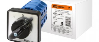
In some schemes, the first circuit breaker is replaced with a packet switch, and less powerful circuit breakers are then installed on consumer lines. This option also does not contradict the rules.
Image gallery
Photo from
General diagram for connecting a single-phase RCD
Differences between fire and conventional RCDs
Differential current switch and automatic circuit breaker
Installation of protective devices in different electrical networks
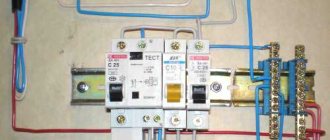
When connecting wires, it is important to ensure that the outputs from the RCD are not combined at a common zero and do not intersect anywhere with other neutral conductors or the panel body. After this protective device, the line should immediately go to another RCD or circuit breaker, and then directly to consumers.
After installation is completed, it is necessary to check the correct assembly of the entire circuit and the functionality of the protective device.
First, some equipment is plugged into the outlet to create a load in the network and voltage is applied. If everything is correct and the insulation is intact everywhere, then no RCD trips should occur
Then the differential switch itself is checked. To do this, most RCDs have a “T” (“TEST”) button. When it is pressed, the calculated leakage current is simulated, as a result of which the protection should operate normally. Moreover, testing should work regardless of whether there is a load or not.
If when you press “TEST” the RCD does not disconnect the line, then it is faulty. It is possible that the leakage simulation circuit is broken. In this case, the protection device will continue to perform its functions as intended. However, even such a switch is better to be replaced immediately. It is recommended to carry out such a check once a month.
How to choose an RCD?
In order to correctly select the RCD, it is necessary to ensure that the selected current rating of the device
is one step higher than the current rating of the corresponding group circuit breaker.
The rating of the input RCD must be higher than or equal to the rating of the input circuit breaker. In this case, this device will be protected by the machine from short circuit currents. The differential current rating, to protect a person from electric shock, is usually selected at 30 mA
. For rooms with increased danger - 6 or 10 mA (the same value of the differential current is selected when the protection is for one device). An RCD with a differential current value of 100 or 300 mA is installed, if necessary, after the input circuit breaker. But it protects not from electric shock, but from fire (it is often called “firefighter”). You can pre-select the RCD using the selection table, taking into account the load power and differential current. It is important to take into account the recommendations given above.
How does an RCD work?
There are two types of devices:
- electromechanical;
- electronic models of RCDs.
Electromechanical
These devices consist of several parts:
- zero sequence electric current transformer. It monitors leaks and transfers energy to the secondary winding of the transformer;
- magnetoelectric element performing threshold functions;
- a relay that is triggered when a magnetoelectric “latch” is triggered.
All mechanical parts must be very high-precision, which is why the cost is high. But it is compensated by reliability and the ability to work without additional power, detecting leaks at any voltage value. The independence factor is extremely important: a mechanical RCD will detect a leak and turn on the relay in 100 percent of cases. For electronic devices, this percentage is lower, since if the total voltage level is below a certain threshold, the circuit will be inoperable. Therefore, it is electromechanical models that are internationally recognized as the standard and mandatory for use, especially at critical facilities.
Electronic RCDs
Their cost is sometimes an order of magnitude lower than the classic ones. But there is also the above-mentioned drawback - not a 100% guarantee of operation. The design of such protection systems is similar to that of electromechanical ones. But instead of a sensitive element, a logical comparison unit is installed - a zener diode, a comparator. The functionality of the device is ensured by the filter and rectifier.
A signal amplifier is also required, since the included transformer is a step-down transformer. Unfortunately, the amplifier modulates not only the “useful” load, but also noise, which also reduces reliability. But to protect an ordinary residential premises, an electronic RCD in quite a number of cases is sufficient. The choice should be based on the details of the electrical installation project being implemented.
Connecting an RCD to a single-phase network (with and without grounding)
Users often ask the question, should they install an RCD before or after the machine? To do this, consider the most common scheme for connecting one RCD and several group circuit breakers in a single-phase network. In the correct connection diagram,
the RCD is installed after the input circuit breaker.
The connection sequence is as follows: input machine - meter - RCD. The diagram shows one RCD, but there can be several of them (in turn with one or more group circuit breakers). This may be necessary if you plan to protect a specific group of consumers separately. For example, you have a separate line to a washing machine, and you want to install an RCD for it with a differential current of 10 mA and a separate circuit breaker. In a group, an RCD is first installed, and then a circuit breaker (or several circuit breakers). Above was a diagram of a single-phase network with grounding (TN-S diagram). In older houses, the TN-C (two-wire) power supply circuit is still used. In such a network, the PEN wire combines the functions of a working neutral and a protective conductor. In a two-wire network without grounding, the RCD also protects against electric shock, but it is triggered not when current enters the current-carrying body of a home appliance, but later, when a person touches the body that has become energized. From the figure below it can be seen that there are practically no changes in the inclusion of the RCD itself in such a circuit. It is only important to remember one point: if you have a three-wire cable running from consumers (electrical appliances, lighting) into the switchboard, the grounding wire in the switchboard must be left unconnected, and the phase and neutral conductors must be connected as indicated in the diagram. How many machines
can be connected to one RCD? The number of group circuit breakers connected after the RCD depends on their total current rating (which in general should not exceed the current rating of the RCD) and the total leakage current of the protected network. There are current leaks in any working network, the main thing is that they do not exceed the established standards. An increase in leakage currents may be a consequence of insulation aging, damage, or malfunction of electrical appliances. The total value of the leakage current of the protected section of the network in normal operation according to regulatory documents should not exceed 1/3 of the rated current of the RCD, i.e. for RCD 30mA should not exceed 10mA. If there is no real data on leakage in the network, then calculated values are taken: for consumers (electrical appliances) 0.4 mA per 1 A of load current + leakage current of the wiring itself - at the rate of 10 μA per 1 m of conductor length. Exceeding the total network leakage current above the threshold value of the RCD can lead to false alarms. In turn, this signals that most likely it is necessary to install an additional RCD (especially if you have more than two or three machines after the RCD and preliminary calculations/measurements of the leakage current have not been carried out). The excess of the total value of the ratings of group circuit breakers over the rating of the RCD current is not critical if it also exceeds the rating of the input circuit breaker. If the rating of the RCD is selected correctly (that is, higher than the rating of the input machine), then the RCD will be protected in this case by the input machine.
RCD
To bookmarks
In this article we will consider the following questions:
- What is an RCD
- Design and operating principle of RCD.
- RCD connection diagram.
- Errors in connection diagrams due to which the RCD trips.
- How to choose an RCD? Types and characteristics of RCD.
What is an RCD
RCD (Residual Disconnection Device) is a switching device designed to protect an electrical circuit from leakage currents, that is, currents flowing along undesirable, under normal operating conditions, conductive paths, which in turn provides protection from fires (electrical wiring fires) and from injury to humans electric shock.
The definition of “switching” means that this device can turn on and off electrical circuits, in other words, switch them.
RCD also has other names, for example: differential switch, differential current switch, (abbreviated as differential current switch), etc.
Design and operating principle of RCD
And so, for clarity, let’s present the simplest diagram of connecting a light bulb through an RCD:
The diagram shows that during normal operation of the RCD, when its moving contacts are closed, a current I1 of, for example, 5 Amps from the phase wire passes through the magnetic circuit of the RCD, then through the light bulb, and returns to the network via the neutral conductor, also through the magnetic circuit RCD, in which the value of the current I2 is equal to the value of the current I1 and is 5 Amperes.
According to the law of electromagnetic induction, current I1 passing through the magnetic circuit of the RCD creates in it a magnetic flux F1 with a conventional value equal to 5 units, in turn, current I2 also creates a magnetic flux F2 in the magnetic circuit of the same value equal to 5 units, but since the direction of the current I2 is opposite to the direction current I1, then the magnetic flux F2 created by it is also opposite to the magnetic flux F1, i.e. magnetic fluxes F1 and F2 are directed counter to each other and, accordingly, with equal values of the incoming and outgoing currents, they balance each other, as a result of which the total magnetic flux in the magnetic core is zero:
Fsum= Ф1+ Ф2=5+(-5)=0
Since the total magnetic flux in the magnetic circuit is absent (equal to zero), no current is induced in the secondary winding. The moving contacts are closed, the electrical circuit is turned on and is in normal operation.
Now imagine that a person touched one of the wires of the electrical circuit. In this case, part of the electric current begins to flow through the human body, creating an immediate threat to his life and health:
In such a situation, part of the electrical circuit current coming from the phase wire will not return to the network, but passing through the human body will go into the ground; therefore, the current I2 that will return to the network through the magnetic circuit of the RCD along the neutral wire will be less than the current I1 entering the network, respectively the value of magnetic flux F1 will become greater than the value of magnetic flux F2, as a result of which the total magnetic flux in the RCD magnetic circuit will no longer be equal to zero.
For example, current I1=6A, current I2=5.5A, i.e. 0.5 Ampere flows through the human body into the ground (i.e. 0.5 Ampere is the leakage current), then the magnetic flux F1 will be equal to 6 conventional units, and the magnetic flux F2 will be 5.5 conventional units, then the total magnetic flux will be equal to :
Fsum= Ф1+ Ф2 =6+(-5.5)=0.5 arb. units
The resulting total magnetic flux induces an electric current in the secondary winding, which, passing through the magnetoelectric relay, puts it into operation, and it, in turn, opens the moving contacts, turning off the electrical circuit.
The functionality of the RCD is checked by pressing the “TEST” button. Pressing this button artificially creates a current leak in the RCD, which should lead to the RCD turning off.
RCD connection diagram.
IMPORTANT! Since the RCD does not have overcurrent protection, any circuit for its connection must also provide for the installation of a circuit breaker to protect the RCD from overload and short-circuit currents.
The RCD is connected according to one of the following schemes, depending on the type of network:
Connecting an RCD without grounding:
This scheme is used, as a rule, in buildings with old electrical wiring (two-wire), in which there is no ground wire.
Connecting an RCD with grounding:
Connection diagram of an RCD in the electrical network of the T N- C- S (when the neutral conductor is divided into a neutral working and a neutral protective):
Read about how to properly perform grounding here.
Connection diagram of the RCD in the electrical network of the T N- S (when the neutral working and neutral protective conductors are separated):
IMPORTANT! In the coverage area of the RCD, you cannot combine the neutral protective (grounding wire) and the neutral working conductors! In other words, it is impossible in the circuit, after the installed RCD, to connect the working zero (blue wire in the diagram) and the ground wire (green wire in the diagram).
Errors in connection diagrams due to which the RCD trips.
As mentioned above, the RCD is triggered by leakage currents, i.e. if the RCD has tripped, this means that a person has come under voltage or for some reason the insulation of the electrical wiring or electrical equipment has been damaged.
But what if the RCD trips spontaneously and there is no damage anywhere, and the connected electrical equipment is working properly? Perhaps the whole point is one of the following errors in the network diagram of the protected RCD.
One of the most common mistakes is combining the neutral protective and neutral working conductors in the coverage area of the RCD:
In this case, the amount of current leaving the network through the RCD along the phase wire will be greater than the amount of current returning to the network through the neutral conductor because part of the current will flow past the RCD along the grounding conductor, which will cause the RCD to trip.
Also, there are often cases of using a grounding conductor or a third-party conductive grounded part (for example, building fittings, a heating system, a water pipe) as a neutral working conductor. This connection usually occurs when the neutral working conductor is damaged:
Both of these cases lead to the RCD tripping, because The current leaving the network through the phase wire does not return through the RCD back to the network.
How to choose an RCD? Types and characteristics of RCD.
To choose the right RCD and eliminate the possibility of error, use our online calculator for calculating the RCD by power.
The RCD is selected according to its main characteristics. These include:
- Rated current - the maximum current at which the RCD is able to operate for a long time without losing its functionality;
- Differential current - the minimum leakage current at which the RCD will disconnect the electrical circuit;
- Rated voltage - the voltage at which the RCD is able to operate for a long time without losing its functionality
- Type of current - direct (indicated by “-“) or alternating (indicated by “~”);
- Conditional short circuit current is the current that the RCD can withstand for a short time until the protective equipment (fuse or circuit breaker) trips.
The choice of RCD is based on the following criteria:
— By rated voltage and type of network: The rated voltage of the RCD must be greater than or equal to the rated voltage of the circuit it protects:
U nom. RCD ⩾ U nom. networks
For a single-phase network, a two-pole RCD is required ; for a three-phase network , a four-pole RCD .
— By rated current: according to paragraph 7.1.76. PUE, the use of RCDs in group lines that do not have overcurrent protection, without an additional device that provides this protection, is not allowed, and a calculated check of the RCD in overcurrent modes is necessary, taking into account the protective characteristics of the higher-level device that provides overcurrent protection.
From the above it follows that in front of the RCD there must be a protection device (circuit breaker or differential circuit breaker); it is according to the current of this higher-level protection device that the rated current of the RCD must be selected based on the condition that the rated current of the RCD must be greater than or equal to the rated current of the one installed before it protection device:
Inom. RCD⩾ Inom. protection device
In this case, it is recommended that the rated current of the RCD be one step higher than the rated current of the higher-level protection device (for example, if a 25 Ampere circuit breaker is installed in front of the RCD, it is recommended to install the RCD with a rated current of 32 Amps)
For reference - standard values of RCD rated currents: 4A, 5A, 6A, 8A, 10A, 13A, 16A, 20A, 25A, 32A, 40A, 50A, 63A, etc.,
— By differential current:
Differential current is one of the main characteristics of the RCD, which shows at what value of leakage current the RCD will turn off the circuit.
In accordance with clause 7.1.83. PUE: The total leakage current of the network, taking into account the connected stationary and portable electrical receivers in normal operation, should not exceed 1/3 of the rated current of the RCD. In the absence of data, the leakage current of electrical receivers should be taken at the rate of 0.4 mA per 1 A of load current, and the network leakage current at the rate of 10 μA per 1 m of phase conductor length. Those. The differential network current can be calculated using the following formula:
ΔInetwork=((0.4*Inetwork)+(0.01*Lwire))*3, milliAmpere
where: I network - network current (calculated using the formula above), in Amperes; L wires - the total length of the protected electrical network wiring in meters.
Having calculated ΔInetwork we accept the nearest higher standard value of the differential current of the RCD ΔIRCD :
ΔIRCD⩾ ΔInetwork
Standard values of RCD differential current are : 6, 10, 30, 100, 300, 500 mA
Differential currents: 100, 300 and 500 mA are used for protection against fires, and currents: 6, 10, 30 mA are used to protect against electric shock. In this case, currents of 6 and 10 mA are used, as a rule, to protect individual consumers and premises with increased danger, and a differential current of 30 mA is suitable for general protection of the electrical network.
If an RCD is needed to protect against electric shock, and according to the calculation, the leakage current is more than 30 mA, it is necessary to provide for the installation of several RCDs on different groups of lines, for example, one RCD to protect sockets in rooms, and a second to protect sockets in the kitchen, thereby reducing the most power passing through each RCD and, as a result, reducing the network leakage current, i.e. in this case, the calculation will need to be made for two or more RCDs that will be installed on different lines.
— By type of RCD:
There are two types of RCDs: electromechanical and electronic . We discussed the principle of operation of an electromechanical RCD above; its main working element is a differential transformer (magnetic core with a winding) that compares the magnitude of the current going into the network and the current returning from the network, and in an electronic device this function is performed by an electronic board that requires voltage to operate.
Let’s imagine a situation: for some reason the zero “disappeared” (for example, the neutral conductor burned out), and if an electronic RCD is installed in the network, its electronic board will be de-energized and if a person touches the phase wire and comes under voltage, this RCD will not work, but the electromechanical The RCD will remain operational even in the absence of voltage and will disconnect the electrical circuit, so it is preferable to use an electromechanical RCD.
Was this article useful to you? Or maybe you still have questions ? Write in the comments!
Didn’t find an article on the website on a topic that interests you regarding electrical engineering? Write to us here. We will definitely answer you.
↑ Up
10
https://elektroshkola.ru/apparaty-zashhity/uzo/
Connection to a three-phase network (with and without grounding)
Connecting an RCD in a three-phase network with grounding is not much different from a single-phase one. Protection of three-phase load circuits is carried out by a three-phase (four-pole RCD). In this case, single-phase load circuits must be protected with a separate single-phase (two-pole) RCD. There are many schemes on the Internet where a three-pole RCD is used simultaneously to protect both three-phase and single-phase consumers. This is only permissible if the RCD is fireproof, with a leakage current of 100 mA or more. Connecting an RCD in a three-phase network without grounding is prohibited by the PUE.
Schemes for 3-phase network
In homes, industrial premises and other structures, there may be a different option for arranging power supply.
Thus, for apartments, connecting a 3-phase network is uncharacteristic, but for equipping a private house this option is not uncommon. Here other circuits for connecting the protection device will be used.
Option #1 – general RCD for a 3-phase network + group RCDs.
For a 380 V network, a 2-pole device is not enough; a 4-pole analogue is needed: you need to connect 1 neutral wire and 3 phase wires.
The circuit is complicated by equipping each power line with a separate RCD device. This is not necessary, but duplicate protection is recommended for additional protection against leakage currents
The type of wires is important. For a 1-phase network, a standard VVG cable is suitable, while for a 3-phase network it is recommended to install the more fire-resistant VVGng cable. We wrote about choosing the appropriate type of wire in our other article.
Option #2 – general RCD for 3-phase network + meter.
This solution completely repeats the previous one, but an electricity meter is added to the circuit. Group RCDs are also included in the system for servicing individual lines.
Of all the presented diagrams, this is the most voluminous in the literal sense, that is, it requires the installation of a large electrical panel with many wires and connected electrical appliances
There is a nuance that applies to any of the presented schemes. If an apartment or house has several lighting and socket circuits, several powerful household appliances that require the installation of separate power lines, then it makes sense to install double protection with a common RCD.
Otherwise, either a common device or one for each circuit is sufficient.
RCD connection errors
The most common RCD connection errors are related to incorrect connection of the neutral conductor. One of the most common
connection errors is connecting the neutral conductor from the output of the RCD to the common neutral bus. Moreover, it is incorrect to either directly connect any group of sockets (protected by an RCD) to the common shield neutral conductor bus, or to combine the common neutral bus with the N bus after the RCD (intended for the neutral conductors of protected load groups). Another error is related to the connection of neutral conductors of different consumer groups. The neutral conductor after the RCD must be connected directly to the load of the groups powered through it, without connecting to the neutral conductors of groups not protected by the RCD or protected by another RCD. Also, you cannot combine the neutral conductor after the RCD with the protective grounding conductor (that is, combine the working and protective zero).
Selection by installation type
The devices are available in two versions:
- modular _ Equipped with structural elements for installation on a DIN rail, mounted in a distribution board. Usually they serve a group of several outlets;
- portable _ Less common option. It is plugged into an outlet, after which an electrical appliance is connected to it. It can also be made in the form of an extension cord.
How to check the RCD for functionality?
You can check the performance of the RCD in the 4 most well-known ways:
- Using the TEST button
- Battery test
- Using an incandescent light bulb
- Checking with a tester
The most popular are the first two methods, which require less effort and available means.
- To check the residual current device, just press the “Test” button (all these devices are equipped with this button). When pressed, a resistance is connected inside the circuit, simulating leakage current. In this case, a working device disconnects the load circuit.
- Take a regular AA battery and connect two pre-prepared wires to it, preferably of different colors. Cock the lever of the device and touch the free ends of the wires to both terminals of any of the poles (either phase or neutral). Then reverse the polarity. A working RCD should trip when at least one polarity is connected (type A RCD should trip with any polarity, type AC - only with one).
An important point: you can use a battery to check an electromechanical RCD; an electronic RCD will not work in any polarity, since for its operation you need to specially supply power. Dear users, thank you for reading this article to the end! We would like to remind you that in our online store you will find a wide selection of various protection devices: RCDs, differential circuit breakers and overcurrent circuit breakers. We are always ready to offer low prices, convenient delivery and a quality guarantee!
How it works
The principle of operation of an RCD in a single-phase network is simple. The device detects leakage electric currents going to ground and turns off the circuit. Detection is performed based on the difference in types of currents:
- energy leaving the RCD;
- electricity returning to the system.
In a working electrical network, these currents are equal in strength, but the direction should be opposite. If for some reason a leak occurs (broken insulation, touching a wire, and other situations), part of the electricity will go through a new “channel” to the “ground”. The electric current going to the residual current device will become less than the outgoing one. A similar thing will happen after some part comes under electrical voltage - for example, a housing or other conductive parts.
The difference in current readings is recorded by a transformer assembly with a ring core. The primary winding (neutral and phase) is located inside. The secondary winding is connected directly to the actuator that opens the electrical circuit. The circuit will operate without the presence of a person as a source of failure, detect a leak and remove power from the damaged line.
The operating principle of a two-phase RCD-D is described above. There are also three-phase protective devices: they detect leaks and unbalanced load distribution. These are more advanced devices that provide an additional level of protection.
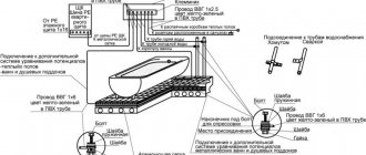
Installation instructions
Before installation, you first need to select a location for installation. For installation work, use a metal or plastic cabinet. They come in different sizes; you need to count the number of devices in advance to choose the right size.
Some models are equipped with viewing windows for taking meter readings.
How to correctly connect RCDs and machines yourself, basic rules:
- We begin any work after turning off the power supply.
- When installing wiring and protective devices, strictly follow the selected diagram; it is better to keep it in front of you.
- Connect wires strictly by color marking. Strip the ends of the wires by 0.5 cm and secure with screws.
- All protective devices, circuit breakers, voltage relays are mounted on a DIN rail. To fix them, engage the upper clamp, use a screwdriver to bend the lower clamp and press on the device, when it is in place, release the lower clamp.
- Label all protective devices on the panel so that you know which devices are connected through them.
- The machine is connected to the input wires first, only after it are all other devices installed.
- When choosing an input RCD, we calculate its parameters depending on the current flowing in the network. For example, for a current of 20-25 amperes, you should take a 32A protective disconnect device.
You might be interested in the article “Installing a toilet with your own hands: step-by-step connection instructions” Go>>
If a false shutdown occurs or the device does not work on the contrary, the reason may be the following:
- phase and neutral wires are connected after the RCD;
- check whether the neutral wire is secured;
- the neutral wire and ground are connected in the socket;
Safety rules for installing RCD meters and automatic machines
When connecting protection devices, a number of safety regulations must be observed. Not only does this help ensure proper connections, but it will also save your life.
How to properly connect RCDs and circuit breakers, basic rules for safe installation:
- Start work only after completely turning off the power. The presence of current in the network can be checked using a tester or a regular test light.
- Label the connected wires. Use colored electrical tape or special heat-shrinkable tubes of different colors for this.
- Connect and extend wires using special terminal blocks, clamps, and sleeves.
- After connecting the wire to the machine or other device, check the reliability of the connection. Try pulling out the wire. The next day after installing the panel, tighten all the screws again.
- Be careful when connecting power for the first time. Short circuits and sparks are possible. Stay away from the control room.
- Test the protection device by pressing the “test” button.
- Do not use heating or water supply pipes in the apartment for grounding.
Purpose and operating principle of RCD
The operation of the residual current device is based on a constant comparison of the current values that flow through the phase and neutral conductors. If you touch a live wire, some of the current will pass through the human body. Almost instantly (0.2-0.4 seconds) the RCD trips and cuts off the current, because the values of the phase and zero currents are unequal.
Installation of heated electric floors: types, power calculations, pitch
An RCD will not only save you from electric shock, but also prevent fires. If the insulation is damaged, current leakage begins. At the point of current leakage, heating occurs and the wiring may catch fire. If there is a shutdown protection device in the circuit, this situation is impossible.
If your apartment currently does not have a security device, we recommend purchasing one. How to connect an RCD before or after the machine, what other types of protective devices exist, we will consider further.