When building electronic devices, you often have to deal with an inductive circuit element. When only the inductance value L is indicated in the drawing, you have to calculate the inductor yourself. There are many programs on the Internet that allow you to calculate the inductance of coils online using a special calculator. Knowing how the element is structured, you can manually perform all the calculations.
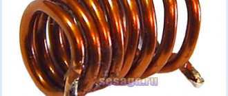
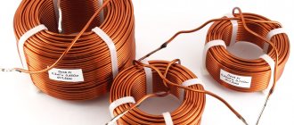
Coil appearance
What is an inductor
This element is also called a choke. This is an insulated wire rolled into a spiral. Such a spiral is characterized by large inductive and small capacitive parameters.
Important! The inductor prevents the flow of alternating current because it has significant inertia. It prevents any change in the current passing through the turns. It makes no difference whether it increases or decreases.
In this regard, these elements are used in electrical engineering to implement:
- current limiting;
- weakening of beats;
- interference suppression;
- magnetic field formation;
- manufacturing motion sensors.
The choke is part of the oscillatory circuit system in resonance circuits and is used in delay lines.
Application of L in an oscillating circuit
Calculation
Formula – formula of an oscillatory circuit
Where L is the element itself, which accumulates magnetic energy.
At the same time, the period of free oscillations of this circuit is calculated by:
Formula – period of free oscillations
Where C is a capacitor, a reactive element of the circuit that stores electrical energy in a particular circuit. The amount of inductive reactance in such a circuit is calculated by XL = U/I. Here X is the capacitance. When calculating a resistor, the main parameters of this element are inserted into the example.
The inductance of the solenoid is determined by the formula:
Formula - inductance of the solenoid coil
In addition, the inductance level has a certain dependence on the temperature on the board. Parallel connection of several parts, changes in the density and size of winding turns and other parameters affect the basic properties of this element.
Photo – temperature dependence
To find out the parameters of the inductor, you can use various methods: measure with a multimeter, test with oscilloscopes, check separately with an ammeter or voltmeter. These options are very convenient because they use capacitors as reactive elements, the electrical losses of which are very small and may not be taken into account in the calculations. Sometimes, in order to simplify the task, a special program for calculating and measuring the required parameters is used. This allows you to significantly simplify the selection of the necessary elements for the circuits.
You can buy inductors (SMD 150 μH and others) and wires for winding them at any electrical store; their price varies from $2 to several dozen.
Inductors are designed to filter high frequency currents. They are installed in oscillating circuits and are used for other purposes in electrical and electronic circuits. A ready-made factory-made device is more reliable in operation, but more expensive than one made by hand. In addition, it is not always possible to purchase an element with the necessary characteristics. In this case, the calculation of the inductor and the device itself can be done independently.
What parameters does the coil have?
Its design depends on where the inductive element will be used and at what frequency it will operate. There are general parameters:
- L – inductance;
- R sweat – loss resistance;
- Q – quality factor;
- its resonance and parasitic capacitance;
- coefficients TKI and TKD.
Transformer calculation
Inductance (self-inductance coefficient) L is the main electrical characteristic of the element, which shows the amount of energy accumulated by the inductor when current flows. The greater the inductance, the higher the energy in the coil. Unit of measurement L – 1 Hn.
When current and magnetic field interact in the winding, harmful phenomena occur. They contribute to the occurrence of losses, which are denoted by R sweat. The loss formula looks like:
R sweat = rω + rd + rs + re.
The terms of the formula are losses:
- rω – in wires;
- rd – in dielectric;
- rs – in the core;
- re – for eddy currents.
As a result of such losses, the impedance of an inductive two-terminal network cannot be called entirely reactive.
The quality factor of a two-terminal network is determined by the formula:
Q = ω*L/R sweat,
where ω*L = 2π*L – reactance.
When winding the turns of an element, unnecessary capacity appears between them. Because of this, the choke turns into an oscillatory circuit with its own resonance.
TCI is an indicator describing the dependence of L on Т0С.
TKD is an indicator that describes the dependence of the quality factor on T0C.
Information. Changes in the main parameters of an inductive two-terminal network depend on the TCI, TKD coefficients, as well as on time and humidity.
Operating principle
The operation scheme of active inductors is based on the fact that each individual turn of the winding intersects with magnetic lines of force. This electrical element is necessary in order to extract electrical energy from a power source and convert it to store it in the form of an electric field. Accordingly, if the circuit current increases, then the magnetic field expands, but if it decreases, the field will invariably contract. These parameters also depend on frequency and voltage, but in general, the effect remains unchanged. Turning on the element produces a phase shift in current and voltage.
Photo - principle of operation
In addition, inductive (frame and frameless) coils have the property of self-induction, its calculation is made based on the data of the nominal network. In multilayer and single-layer windings, a voltage is created that is opposite to the voltage of the electric current. This is called EMF; the determination of electromotive magnetic force depends on inductance values. It can be calculated using Ohm's law. It is worth noting that regardless of the network voltage, the resistance in the inductor does not change.
Photo - connection of individual terminals of elements
The connection between inductance and the concept (change) of EMF can be found using the formula εc = - dФ/dt = - L*dI/dt, where ε is the value of self-induction EMF. And if the rate of change of electrical energy is equal to dI/dt = 1 A/c, then L = εc.
Video: calculating an inductor
Coil design
Inductive elements differ in design:
- type of winding: helical, screw; ring;
- number of layers: single-layer or multi-layer;
- type of insulated wire: single-core, stranded;
- the presence of a frame: framed or frameless (with a small number of turns of thick wire);
- frame geometry: rectangular, square, toroidal;
- the presence of a core: ferrite, carbonyl iron, electrical steel, permalloy (soft magnetic alloy), metal (brass);
- core geometry: rod (open), ring-shaped or w-shaped (closed);
- the ability to change L in narrow intervals (movement of the core relative to the winding).
Calculation of voltage drop in a cable
There are flat coils that are printed and installed on the boards of digital devices.
For your information. Wire winding can be either ordinary (turn to turn) or in bulk. The latter method of laying the wire reduces parasitic capacitance.
Coil design
Design
The main purpose of inductors GOST 20718-75 is the accumulation of electrical energy within a magnetic field for acoustics, transformers, etc. They are used for the development and construction of various selective circuits and electrical devices. Their functionality, size and area of use depend on the design (material, number of turns), the presence of a frame. The devices are manufactured in factories, but you can make them yourself. Homemade elements are somewhat inferior in reliability to professional ones, but are several times cheaper.
Photo - diagram
The frame of the inductor is made of dielectric material. An insulated conductor is wound around it, which can be either single-core or multi-core. Depending on the type of winding, they are:
- Spiral (on a ferrite ring);
- Screw;
- Screw-spiral or combined.
A notable feature of an inductor for electrical circuits is that it can be wound either in several layers or unified, i.e., with scraps. If a thick conductor is used, then the element can be wound without a frame, if thin, then only on a frame. These inductor frames come in different cross-sections: square, round, rectangular. The resulting winding can be inserted into a special housing of any electrical device or used openly.
Photo - design of a homemade element
Cores are used to increase inductance. Depending on the purpose of the element, the rod material used varies:
- With ferromagnetic and air cores they are used at high current frequencies;
- Steel ones are used in low voltage environments.
Based on the principle of operation, there are the following types:
- Contour. They are mainly used in radio engineering to create oscillatory circuits on boards and work together with capacitors. The connection uses a serial connection. This is a modern version of the flat Tesla coil;
- Variometers. These are high-frequency tunable coils, the inductance of which can be controlled, if necessary, using additional devices. They represent a connection of two separate coils, one of which is movable and the other is not;
- Twin and tuning chokes. The main characteristics of these coils: low resistance to direct current and high resistance to alternating current. Chokes are made of several coils connected by windings. They are often used as a filter for various radio devices, installed to control interference in antennas, etc.;
- Communication transformers. Their design feature is that two or more coils are installed on one rod. They are used in transformers to provide a specific connection between the individual components of a device.
The marking of inductors is determined by the number of turns and the color of the housing.
Photo – marking
Why do you need to calculate inductance?
Inductance: formula
Calculation of inductance is needed because the coils can be constructed differently. The use of chokes in various branches of electrical and electronics, their operation under the influence of direct and alternating current, requires careful selection of inductance, quality factor and stability of operation. When making chokes of a given parameter L with your own hands, you need to perform a calculation. For each type of inductive two-terminal network, its own formula is used.
Comparison of a round section with a flat one
Typically, low-frequency inductor designs use wires with a round cross-section. However, a conductor is subject to skin effect at high frequencies, when electrons move across a thin layer of the conductor's surface rather than across its entire cross-section. This means that round wires operating at high frequencies have greater resistance to alternating current. DC-DC converters with higher current and switching frequency requirements may require switching to a high-current, shielded, flat-wire inductor. Bourns' SRP series of shielded inductors includes several flat wire options for high current and high frequency applications. At the same time, it is worth noting that the cross-sectional area is the same for flat and round wire, as shown in Figure 1, and the surface area of flat wire is about 60% larger.
Rice. 1. Cross-sectional area and surface area of flat and round conductors
This provides a larger current flow area to combat skin effect at frequencies up to 5 MHz and helps achieve higher inductance values. Higher current values can also be obtained based on the flat wire design. the SRP5030CA flat wire inductor is 5.5 mm wide by 2.9 mm high, which is the same dimensions as the conventional SRP5030C inductor, but the SRP5030CA provides higher (30 to 40%) operating and saturation current values at the same inductance.
Calculation of coil parameters
We have to consider different options when making calculations. The calculation of inductance depends on the initial data and the specified final parameters.
Calculation of L depending on the given design
If the initial parameters are: w , D frame and the length of the wound wire, then the formula for calculation is:
L = 0.01*D*w2/(l/D) + 0.46,
Where:
- D – frame diameter, cm;
- w – number of turns;
- l – winding length, cm;
- L – inductance, µH.
Substituting numerical values into the formula, the value of L is obtained.
Calculation of the number of turns by inductance
Knowing D frame and L , calculate the number of turns in the coil, the formula looks like:
w = 32*√(L*D),
Where:
- L – inductance, µH;
- D – frame diameter, mm.
If the length of the conductor wound in a row and its diameter are taken as the initial parameters, then the number of turns is found using the formula:
w = l/d,
Where:
- l – winding length, mm;
- d – wire diameter, mm.
Wire diameter measurements are carried out with a ruler or caliper.
Calculation of inductance of a straight wire
When planning to find L of a round straight conductor, we turn to the approximate formula:
L = (μ0/2π)*l*( μe*ln(l/r) + 1/4* μi,
Where:
- μ0 – magnetic constant;
- μe – relative magnetic permeability (RMP) of the medium (for vacuum – 1);
- μi – conductor OMF;
- l – wire length;
- r is the radius of the wire.
The formula is valid for a long conductor.
Calculation of single-layer winding
Single-layer chokes without a core can be easily and quickly calculated using an online calculator, in the window of which you can enter all known characteristics, and the program will display the value L.
Calculations are also carried out manually, using a mathematical expression. It looks like:
L = D2*n2/45D + 100*l,
Where:
- D – coil diameter, cm;
- l – length of the wound wire, cm;
- n – number of turns.
The formula is suitable for calculating L chokes without ferrite cores.
Single layer coil turn to turn
Core choke
If there is a core, its size and shape should be taken into account. In the case of identical coils, the inductance is greater in the one located on the core.
Calculation of single-layer winding with core
Multilayer winding
Features of the calculation with this method of winding wire are that you need to take into account its thickness. The formula for a coreless choke is:
N²=(L*(3Dk+9l+10t))/0.008Dk²,
Where:
- Dk – total diameter (diameter of frame and winding);
- t – layer thickness;
- l is the length of the wound wire.
All values are substituted in mm, the value of L is in µH.
Multilayer winding
Design
The main purpose of inductors GOST 20718-75 is the accumulation of electrical energy within a magnetic field for acoustics, transformers, etc. They are used for the development and construction of various selective circuits and electrical devices. Their functionality, size and area of use depend on the design (material, number of turns), the presence of a frame. The devices are manufactured in factories, but you can make them yourself. Homemade elements are somewhat inferior in reliability to professional ones, but are several times cheaper.
Photo - diagram
The frame of the inductor is made of dielectric material. An insulated conductor is wound around it, which can be either single-core or multi-core. Depending on the type of winding, they are:
- Spiral (on a ferrite ring);
- Screw;
- Screw-spiral or combined.
A notable feature of an inductor for electrical circuits is that it can be wound either in several layers or unified, i.e., with scraps. If a thick conductor is used, then the element can be wound without a frame, if thin, then only on a frame. These inductor frames come in different cross-sections: square, round, rectangular. The resulting winding can be inserted into a special housing of any electrical device or used openly.
Photo - design of a homemade element
Cores are used to increase inductance. Depending on the purpose of the element, the rod material used varies:
- With ferromagnetic and air cores they are used at high current frequencies;
- Steel ones are used in low voltage environments.
Based on the principle of operation, there are the following types:
- Contour. They are mainly used in radio engineering to create oscillatory circuits on boards and work together with capacitors. The connection uses a serial connection. This is a modern version of the flat Tesla coil;
- Variometers. These are high-frequency tunable coils, the inductance of which can be controlled, if necessary, using additional devices. They represent a connection of two separate coils, one of which is movable and the other is not;
- Twin and tuning chokes. The main characteristics of these coils: low resistance to direct current and high resistance to alternating current. Chokes are made of several coils connected by windings. They are often used as a filter for various radio devices, installed to control interference in antennas, etc.;
- Communication transformers. Their design feature is that two or more coils are installed on one rod. They are used in transformers to provide a specific connection between the individual components of a device.
The marking of inductors is determined by the number of turns and the color of the housing.
Photo – marking
Equivalent circuit of a real inductor
Each inductor can be represented as an equivalent circuit.
This scheme consists of elements:
- Rw – resistance of the winding with leads;
- L – inductance;
- Cw – parasitic capacitance;
- Rl – loss resistance.
When manufacturing an inductive element, they strive to reduce the amount of loss resistance and parasitic capacitance. When the coil operates at a low frequency, the resistance of its winding Rw is taken into account. Large currents operate at such frequencies.
Throttle equivalent circuit
A correctly calculated inductor will have a high quality factor (180-300) and stable operation under the influence of external conditions (temperature and humidity). Knowing the methods of various winding and pitch manipulation, you can reduce the influence of parasitic factors.
Calculation
Formula – formula of an oscillatory circuit
Where L is the element itself, which accumulates magnetic energy.
At the same time, the period of free oscillations of this circuit is calculated by:
Formula – period of free oscillations
Where C is a capacitor, a reactive element of the circuit that stores electrical energy in a particular circuit. The amount of inductive reactance in such a circuit is calculated by XL = U/I. Here X is the capacitance. When calculating a resistor, the main parameters of this element are inserted into the example.
The inductance of the solenoid is determined by the formula:
Formula - inductance of the solenoid coil
In addition, the inductance level has a certain dependence on the temperature on the board. Parallel connection of several parts, changes in the density and size of winding turns and other parameters affect the basic properties of this element.
Photo – temperature dependence
To find out the parameters of the inductor, you can use various methods: measure with a multimeter, test with oscilloscopes, check separately with an ammeter or voltmeter. These options are very convenient because they use capacitors as reactive elements, the electrical losses of which are very small and may not be taken into account in the calculations. Sometimes, in order to simplify the task, a special program for calculating and measuring the required parameters is used. This allows you to significantly simplify the selection of the necessary elements for the circuits.
You can buy inductors (SMD 150 μH and others) and wires for winding them at any electrical store; their price varies from $2 to several dozen.
What do you mean by the word “reel”? Well... this is probably some kind of “fig” on which threads, fishing line, rope, whatever! An inductor coil is exactly the same thing, but instead of a thread, fishing line or anything else, ordinary copper wire in insulation is wound there.
The insulation can be made of clear varnish, PVC insulation, or even fabric. The trick here is that even though the wires in the inductor are very close to each other, they are still isolated from each other
. If you wind inductor coils with your own hands, do not under any circumstances even think about using ordinary bare copper wire!
Inductance
Any inductor has inductance
.
The inductance of the coil is measured in Henry
(H), denoted by the letter
L
and measured using an LC meter.
What is inductance? If an electric current is passed through a wire, it will create a magnetic field around itself:
Where
B – magnetic field, Wb
I –
Let's take this wire and wind it into a spiral and apply voltage to its ends
And we get this picture with magnetic lines of force:
Roughly speaking, the more magnetic field lines cross the area of this solenoid, in our case the area of the cylinder, the greater the magnetic flux (F)
.
Since an electric current flows through the coil, it means that a current with Current Strength (I) passes through it,
and the coefficient between the magnetic flux and the current strength is called inductance and is calculated by the formula:
From a scientific point of view, inductance is the ability to extract energy from a source of electric current and store it in the form of a magnetic field. If the current in the coil increases, the magnetic field around the coil expands, and if the current decreases, the magnetic field contracts.
Self-induction
The inductor also has a very interesting property. When a constant voltage is applied to the coil, an opposite voltage appears in the coil for a short period of time.
This opposite voltage is called self-induced emf.
This depends on the inductance value of the coil. Therefore, at the moment the voltage is applied to the coil, the current gradually changes its value from 0 to a certain value within a fraction of a second, because the voltage, at the moment the electric current is applied, also changes its value from zero to a steady value. According to Ohm's Law:
Where
I
– current strength in the coil, A
U
– voltage in the coil, V
R
– coil resistance, Ohm
As we can see from the formula, the voltage changes from zero to the voltage supplied to the coil, therefore the current will also change from zero to some value. The coil resistance for DC is also constant.
And the second phenomenon in the inductor is that if we open the circuit between the inductor and the current source, then our self-induction emf will be added to the voltage that we have already applied to the coil.
That is, as soon as we break the circuit, the voltage on the coil at that moment can be many times greater than it was before the circuit was broken, and the current strength in the coil circuit will quietly fall, since the self-induction emf will maintain the decreasing voltage.
Let us draw the first conclusions about the operation of the inductor when DC current is supplied to it. When electric current is supplied to the coil, the current strength will gradually increase, and when electric current is removed from the coil, the current strength will smoothly decrease to zero. In short, the current strength in the coil cannot change instantly.
Types of Inductors
Inductors are divided mainly into two classes: with magnetic and non-magnetic cores
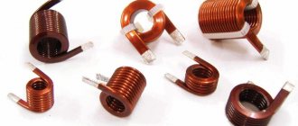
. Below in the photo is a coil with a non-magnetic core.
But where is her core? Air is a non-magnetic core :-). Such coils can also be wound on some cylindrical paper tube. Inductance coils with a non-magnetic core are used when the inductance does not exceed 5 millihenry.
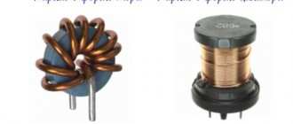
And here are the inductors with a core:
Cores made of ferrite and iron plates are mainly used. The cores increase the inductance of the coils significantly.
Cores in the form of a ring (toroidal) allow you to obtain higher inductance than just cylinder cores.
For medium inductance coils, ferrite cores are used:
Coils with high inductance are made like a transformer with an iron core, but with one winding, unlike a transformer.
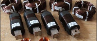
Chokes
There is also a special type of inductor. These are the so-called. An inductor is an inductor whose job is to create a high resistance to alternating current in the circuit in order to suppress high frequency currents.
Direct current passes through the inductor without problems. You can read why this happens in this article. Typically, chokes are connected in the power supply circuits of amplifying devices. Chokes are designed to protect power supplies from high frequency signals (RF signals). At low frequencies (LF) they are used in power supply circuits and usually have metal or ferrite cores. Below in the photo are power chokes:
There is also another special type of chokes - this. It consists of two counter-wound inductors. Due to counter-winding and mutual induction, it is more efficient. Twin chokes are widely used as input filters for power supplies, as well as in audio technology.
Experiments with a coil
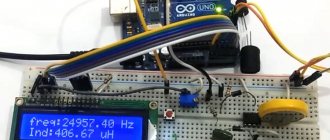
On what factors does the inductance of the coil depend? Let's do some experiments. I wound a coil with a non-magnetic core. Its inductance is so small that the LC meter shows zero to me.
Has a ferrite core
I begin to insert the coil into the core to the very edge
The LC meter reads 21 microhenry.
I insert the coil into the middle of the ferrite
35 microhenry. Already better.
I continue to insert the coil onto the right edge of the ferrite
20 microhenry. We conclude that the largest inductance on a cylindrical ferrite occurs in its middle.
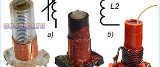
Therefore, if you wind on a cylinder, try to wind in the middle of the ferrite. This property is used to smoothly change the inductance in variable inductors:
Where
1 – this is the coil frame
2 – these are the turns of the coil
3 – core, which has a groove on top for a small screwdriver. By screwing or unscrewing the core, we thereby change the inductance of the coil.
The inductance has become almost 50 microhenry!
Let's try to straighten the turns throughout the ferrite
13 microhenry. We conclude: for maximum inductance, the coil must be wound “turn to turn”.
Let's reduce the turns of the coil by half. There were 24 orbits, now there are 12.
Very low inductance. I reduced the number of turns by 2 times, the inductance decreased by 10 times. Conclusion: the lower the number of turns, the lower the inductance and vice versa. Inductance does not change linearly across turns.
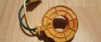
Let's experiment with a ferrite ring.
We measure inductance
15 microhenry
Let's move the coil turns away from each other
Let's measure again
Hmm, also 15 microhenry. We conclude: the distance from turn to turn does not play any role in a toroidal inductor.
Let's make more turns. There were 3 turns, now there are 9.
We measure
Wow! Increased the number of turns by 3 times, and the inductance increased by 12 times! Conclusion: inductance does not change linearly across turns.
If you believe the formulas for calculating inductances, the inductance depends on the “turns squared”.
I won’t post these formulas here, because I don’t see the need. I will only say that inductance also depends on such parameters as the core (what material it is made of), the cross-sectional area of the core, and the length of the coil.
Designation on diagrams
Series and parallel connection of coils
When connecting inductors in series
, their total inductance will be equal to the sum of the inductances.
And with a parallel connection
we get this:
When connecting inductors, the rule must be followed so that they are spatially separated on the board.
This is because if they are close to each other, their magnetic fields will influence each other and therefore the readings of the inductances will be incorrect. Do not place two or more toroidal coils on one iron axis. This may result in incorrect total inductance readings.
Video
Coffee capsule Nescafe Dolce Gusto Cappuccino, 3 packs of 16 capsules
1305 ₽ More details
Coffee capsules Nescafe Dolce Gusto Cappuccino, 8 servings (16 capsules)
435 ₽ More details
AMD Ryzen 5 Processors
Built for high efficiency
Compact flat wire inductor designed to improve efficiency. Flat wire has a high winding ratio of 95%, so spools of flat wire have only 5% wasted space in the gaps between each winding, compared to 30% wasted space in spools of regular round wire. Figure 2 illustrates the space savings due to a high winding ratio with minimal waste in terms of unused space.
Rice. 2. Unused space in flat and round windings
The SRP extruded powdered iron core is molded directly onto the flat wire winding, providing the dual benefit of increasing the conductivity of the conductor when operating at high frequencies, and eliminating the wasted space that can occur with round wire designs.
Figure 3 shows the cross section of two inductors and the space-saving advantage of a flat wire with a powdered iron core.
Rice. 3 Pressed powdered iron core improves efficiency
This technology allows for smaller package size and greater efficiency, with inductance values as low as 47 µH currently available. SRP inductors have high saturation currents of up to 60 A, the values of which are related to the drop in inductance value. Compact cases occupy an area of 4.8 to 14.8 mm and have a height of 2 to 7 mm. Current ratings vary with temperature and range up to 46 A. Bourns continues to expand its range of SRP inductors. The newly released SRP4020FA is 4.1 mm wide and 1.9 mm high and provides inductance in the range of 0.47...4.7 µH and current up to 13.2 A. Another recently released inductor SRP7030CA is 7.8 mm wide and 2.9 mm high, providing inductances of 1...8.2 µH at current levels up to 21.8 A. Future plans for the development and release of SRP series inductors include larger components for higher current values, for example, an inductor with a footprint of 20 mm2, which will provide a saturation current of 150 A. It is also planned to produce smaller inductors with a base area of up to 3 mm2 at a saturation current of 10 A.