This term refers to the coefficient that determines the proportional relationship between the total magnetic flux (Fs) and electric current (I) in a certain circuit. The conductor inductance (L) and the marked parameters are connected in the following formula: Фc = I * L. This publication will help you understand thematic calculations and the use of theoretical knowledge for calculating coils and other special products.
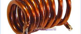
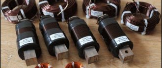
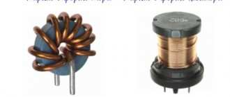
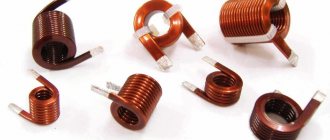
Air inductors with different performance characteristics
Designation and units of measurement
The total magnetic flux (Ff) mentioned above is also called “flux linkage”. This parameter determines the property of a particular conductor to prevent changes in the electric current passing through it. With its help, you can find the value of the created electromotive force (E), determine the power ( W ):
- E = -L* (dI/dt);
- W = (L*I2)/2.
From the above expressions it is clear that the inductance of the conductor depends on the strength of the current, which over a certain period of time is capable of generating an emf in a closed circuit.
For your information. It should be taken into account that when considering the high-frequency range, the influence of inductance is significant even when working with straight sections of conductors.
In the standard international system of units "SI", this parameter is indicated in henry (H). 1 H corresponds to a circuit that forms a potential difference of 1V at the control points. The current in the coil changes by 1 A in one second.
Manufacturing
Inductors can be purchased or made independently. Usually large items are purchased. Probably no one will want to wind the inductor for a fluorescent lamp themselves. Small windings for radio electronics are easy and fun to make with your own hands. Do-it-yourself skills will be useful when repairing coils or changing their operating parameters. To increase their inductance, special magnetic cores are used. They are made from a mixture of iron oxide with oxides of other metals.
Use other online calculators:
The insulated magnetic wire is wound directly onto a magnetic core covered with a thin layer of insulating paper. Before manufacturing, it is necessary to determine the parameters using special calculation formulas or programs. With their help, the size and type of core, the number of turns and the diameter of the wire will be determined.
Use other online calculators:
- Electric cable weight calculation
- Online calculation of current in a circuit
- Convert Watts to Amps
- Voltage loss calculation
- Online calculation of cable cross-section
Theoretical background
The phenomenon under consideration is based on the ability of a conductor to generate a magnetic field when passing an electric current through the corresponding circuit. To facilitate calculations, the following assumptions are possible:
- weakness (slow change) of electric fields;
- constant current in each part of the circuit;
- absence of capacitive components of the conductor.
What does inductance depend on?
For elementary small areas of the experiment, a point distribution of currents (magnetic fields) is taken. The summation of the calculated parameters makes it possible to clarify the dependence of the vector representation of induction (B) on the flux penetrating the surface S. Its edge forms a contour through which current is passed.
In order not to complicate the calculations, the total flow passing through S is considered, without taking into account the complexity of a particular surface. It will be approximately equal to the current. The qualifying coefficient (L) helps to find out the actual value.
For your information. Based on the above reasoning, we can make an intermediate conclusion about the minimum value of the contour shape (when working with low and medium frequencies).
Properties of inductance
The following features of inductance ( L ) must be taken into account during the preparation of design documentation:
- L > 0;
- L depends on the size of the working circuit;
- L is influenced by the magnetic properties of the environment.
The inductance value depends on the magnetic parameters of the core material
Single-turn inductance and coil inductance
Using the above formulas, it is easy to calculate the basic parameters for one turn. The total value of Fs (flux linkage) is equal to the sum of the fluxes through each of the circuits, with the same dimensions of the working elements Ln = L1 * N2, where N is the number of turns.
Important! In real conditions, the structure of magnetic fields differs significantly in the central part and at the edges of the coil.
Solenoid inductance
This term refers to a coil with a length much greater than its diameter. This ratio of geometric dimensions forms parallel lines of force in the center of the structure. For this part, induction is determined by the formula:
B = m * N*I, where m (magnetic constant) = 4*π*10-7 H.
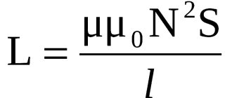
Inductance is determined using the expression:
L = (m*N2*S)/l,
Where:
- S – cross-sectional area of the coil;
- l is the length of the structure.
When installing a core with ferromagnetic properties inside, a correction factor (m1) is additionally applied, which determines the influence of the corresponding material.
Inductance of a toroidal coil (ring-core coil)
To calculate products of this shape, it is permissible to use the standard formula with the following amendments:
L = N2 * (m*m1*S)/(2*π*r),
where r is the radius to the central axis of the torus.
Inductance of a long straight conductor
This design is calculated using the formula:
L = (m/(2*π))*l*(mc*ln(l/r) + mi*1/4),
where mc (mi) are the relative permeabilities of the medium (conductor material), respectively.
In the absence of external interference, the coefficient mc is taken equal to unity.
The program allows you to calculate the following types of inductors:
- Single round turn
- Single-layer turn to turn. Two options can be chosen as initial parameters when calculating the coil:
- The diameter of the frame and the diameter of the wire are known, and the winding length is calculated.
- The frame diameter and winding length are known, the wire diameter is calculated
- Single Layer Pitch Coil
- Coil with non-round turns
- Multilayer coil You can choose two options as initial parameters when calculating the coil:
- The diameter of the frame, the length of the winding and the diameter of the wire are known. The number of turns is calculated, and at the same time the thickness of the coil is determined, its ohmic resistance to direct current and the approximate length of the wire for winding (“how much should be cut”).
- The diameter of the frame, the winding length and the maximum ohmic resistance of the coil are known. The number of turns is calculated, and at the same time the thickness of the coil, the required minimum wire diameter and the approximate length of the wire for winding are determined.
- Toroidal single layer coil
- Ferrite ring coil
- Coil in armored core (Ferrite and carbonyl)
- Thin Film Coil (Flat coil on PCB with round and square turns and as a single straight conductor)
More about Coil32...
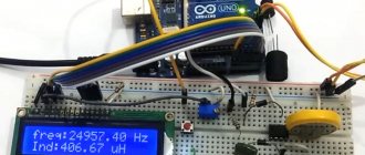
Quite often, a radio amateur is faced with the question: “How to calculate the inductance of a coil?” Coils are used in high-frequency communications equipment, and in the design of acoustic systems, and even looking at the computer motherboard, you will find inductive elements there too. Using the Coil32 program you can quickly calculate the inductance of the coil. The program takes into account the most common options for coil frames. It is possible to calculate a frameless coil in the form of a single turn, on frames of various shapes, on ferrite rings and in armor cores, as well as a flat printed coil with round and square turns. For the calculated coil, you can “without leaving the cash register” calculate the capacitance of the capacitor in the oscillating circuit.
What are the advantages of the program over analogues?
- The program calculates the inductance of many types of coils. You can choose the best option, or recalculate the coil to fit the existing frame.
- The results of all calculations are displayed in a text field, from where they can be saved to a file. In the future, you can view them so as not to recalculate again. You can open this file in MS Word and print it.
- It is possible to calculate the quality factor for radio frequency single-layer inductors.
- The main parameters of the oscillatory circuit for a single-layer coil are calculated
- You can calculate the wire length for winding a single-layer, multi-layer and ferrite ring coil
- For coils in armor cores, it is possible to choose from several standard ones, which allows you to calculate the coil with a few clicks of the mouse.
- For flat coils on a printed circuit board, the program will suggest the optimal dimensions to achieve the highest quality factor.
- On the Internet you can often find programs for calculating inductance that run under DOS; I think there is no need to talk about the advantages of the Windows interface.
- The program has the ability to expand functionality using additional plugins for calculating inductances
- The program has a multilingual interface and skins; additional sets of skins can be found on.
The program is distributed in the "Portable" style and does not have an installer. To install the program, unpack the program archive into any directory and run the Coil32.exe file. If you constantly work with the program, it is advisable to create a special folder for it and place the Coil32.exe shortcut on your desktop.
Inductance table
Inductance: formula
The inductor in an alternating current circuit manifests itself in various ways. As the frequency increases, the so-called “skin” effect begins to have a greater influence. It is caused by surface currents. To correct the field distribution, correction factors are used. In some situations, it is necessary to additionally take into account the effect of vortex components.
Table with formulas for calculating self-inductance of typical closed circuits
How to Calculate the Inductance of a Coreless Multilayer Coil Using a Ruler and an Ohmmeter
- RADIOLOTSMAN magazine, January 2012
- Petr Demchenko, Lithuania
- EDN
- The article shows how to calculate the inductance of a coreless multilayer coil, knowing only its dimensions and DC resistance
- If the coil dimensions are expressed in millimeters, its inductance in microhenry can be calculated using the formula:
Where
- D – average diameter of the coil,
- h – coil height,
- g – depth (winding thickness) of the coil,
- N – number of turns (Figure 1).
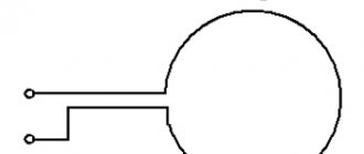
| Picture 1. | Knowing the dimensions and number of turns of the coil, you can calculate its inductance. |
If the number of turns is unknown, the inductance can still be calculated using the DC resistance value of the winding. It is assumed that the coil is wound neatly, turn to turn, with cylindrical enameled wire (Figure 2). In this case, an approximate expression for the number of turns will be as follows:
- where d is the diameter of the wire.
- However, we will assume that the diameter is unknown to us.
Sensors
What does the resistance of a conductor depend on?
Changing the voltage across the inductor is used to control environmental parameters. Such sensors are sensitive to the approach of products with ferromagnetic properties. They are used for contactless fixation of the position of individual parts of mechanisms, gate leaves and other products.
When properly designed, they can withstand adverse external influences well. Potential consumers are attracted by simplicity, reasonable cost, and durability. It is easy to make a functional sensor with your own hands if necessary. Such devices can be easily combined with other components of automation systems.
Equivalent circuit of a real inductor
Each inductor can be represented as an equivalent circuit.
This scheme consists of elements:
- Rw – resistance of the winding with leads;
- L – inductance;
- Cw – parasitic capacitance;
- Rl – loss resistance.
When manufacturing an inductive element, they strive to reduce the amount of loss resistance and parasitic capacitance. When the coil operates at a low frequency, the resistance of its winding Rw is taken into account. Large currents operate at such frequencies.
Throttle equivalent circuit
A correctly calculated inductor will have a high quality factor (180-300) and stable operation under the influence of external conditions (temperature and humidity). Knowing the methods of various winding and pitch manipulation, you can reduce the influence of parasitic factors.
Applications for smartphones, NFC tags and cards
If you use one of the many apps available on Google Play, you can encode NFC tags to perform various tasks, such as
- Change the operating modes of the GPS navigator, Wi-Fi and Bluetooth on your smartphone (turn it on or off).
- Change sound and volume settings (ringer, quiet, loud, vibration only, notification sound, system sounds and alarm volume, vibration on and off).
- Change display settings, such as brightness, auto rotation, turn-on time, and others.
- Interaction with social networks and social media, for example, you can quickly post a photo to a blog.
- Send a message by email or text.
- Open and close applications, open URL.
- Call someone.
- Create various other tasks for NFC tags.
Operating principle of near-contact communication: 1 - NFC reader processor chip, 2 - reader, 3 - NFC tag, 4 - load modulator, 5 - NFC tag chip, 6 - inductive coupling, 7 - data is sent to the load modulator
What happens if you bring your phone with NFC enabled closer to the NFC tag? Suppose you are getting ready to go to bed and touch your phone to the “Alarm Clock” label stuck on your bedside table. The phone periodically activates the NFC chip, which sends a 13.56 MHz AC signal to the loop antenna on the back of the phone. The antenna produces a weak electromagnetic field. This field induces an alternating current in the NFC tag's loop antenna, which is rectified and charges the tag's capacitor. The energy stored in the capacitor is used to power the tag chip, which in turn also generates an alternating current that contains the command to turn on the alarm clock on the phone. The smartphone chip detects the electromagnetic field of the NFC tag loop antenna and decodes the received information. After decoding, the phone runs an alarm program that turns it on.
NFC tag
Benefits of Bourns inductors
Bourns has been a leader in the inductor industry for decades. Bourns is a trusted name and the company's products should be kept in mind when developing new DC/DC converters or other converter designs that require surface mount components. The likelihood of finding the component you need in a product line of 2,000 items is very high, and the product you find will probably exceed your requirements.
However, keep in mind that core loss calculations for a particular application may depend on factors such as magnetic flux density, core loss, and temperature variation. Bourns specialists and the company’s software products will always help with calculations and selection of the right product.
Flat wire chokes of the SRP03\4\5\6* series are designed for applications that require dimensions of the final product, especially its height. The inductors of this family belong to the low-profile class - their height does not exceed 2 mm, which is a competitive advantage when choosing coils for DC/DC used in portable and miniature electronics. At the same time, SRP03\4\5\6* chokes make it possible to obtain a fairly high level of inductance - up to 10 μH - and high operating currents - up to 15.5A. The main parameters of this family are presented in Table 1.
Table 1. SRP03\4\5\6* series chokes with flat wire
| Series name | Dimensions, mm | Inductance range, µH. | Current range, A |
| SRP0310 | 3.4 x 3.1 x 1 | 0.47…4.7 | 1.8…5.6 |
| SRP0312 | 3.4 x 3.1 x 1.2 | 0.47…4.7 | 1.9…6.6 |
| SRP0315 | 3.4 x 3.1 x 1.5 | 0.47…4.7 | 2.3…9 |
| SRP0320 | 3.4 x 3.1 x 2 | 0.47…4.7 | 2.2…7.4 |
| SRP0410 | 4.4 x 4.1 x 1 | 0.47…10 | 1.4…5.2 |
| SRP0412 | 4.4 x 4.1 x 1.2 | 0.47…10 | 1.7…7.6 |
| SRP0415 | 4.4 x 4.1 x 1.5 | 0.47…10 | 1.9…9.3 |
| SRP0420 | 4.4 x 4.1 x 2 | 0.47…10 | 1.8…10.5 |
| SRP0510 | 5.4 x 5.1 x 1 | 0.47…10 | 1.6…5 |
| SRP0512 | 5.4 x 5.1 x 1.2 | 0.47…10 | 2.1…8.3 |
| SRP0515 | 5.4 x 5.1 x 1.5 | 0.47…10 | 2.4…9.5 |
| SRP0520 | 5.4 x 5.1 x 2 | 0.47…10 | 2.4…12.5 |
| SRP0610 | 7.1 x 6.7 x 1 | 0.47…10 | 2…4.7 |
| SRP0612 | 7.1 x 6.7 x 1.2 | 0.47…10 | 2.7…7.7 |
| SRP0615 | 7.1 x 6.7 x 1.5 | 0.47…10 | 3…12,5 |
| SRP0620 | 7.1 x 6.7 x 2 | 0.47…10 | 3.6…15.5 |
The SRP*FA and SRP*CA series flat wire chokes are designed for high current demanding applications, such as DC/DC powering CPU\GPU\ARM, where operating currents can reach tens of amperes. The core of the chokes of this family is made of metal-composite material (rather than ferrite), which makes it possible to obtain ultra-high saturation currents that do not depend on temperature conditions. The main parameters of this family are presented in Table 2.
Table 2. SRP*FA and SRP*CA series chokes with flat wire
| Series name | Dimensions, mm | Inductance range, µH | Current range, A |
| SRP4018FA | 4.1 x 4.1 x 1.8 | 0.33…1.2 | 9.5…15 |
| SRP4020FA | 4.1 x 4.1 x 1.9 | 0.47…4.7 | 5.1…13.2 |
| SRP4030FA | 4.1 x 4.1 x 2.8 | 0.9…6.8 | 4…11.2 |
| SRP5050FA | 5.5 x 5.3 x 4.8 | 5.6…8.2 | 6.1…7.2 |
| SRP6060FA | 6.6 x 6.4 x 5.8 | 2.2…22 | 5…14 |
| SRP5030CA | 5.5 x 5.3 x 2.9 | 0.15…4.7 | 5.9…22.2 |
| SRP6030CA | 6.6 x 6.4 x 2.9 | 0.18…4.5 | 7…32 |
| SRP6050CA | 6.6 x 6.4 x 4.8 | 1…4.7 | 8.5…20 |
| SRP7030CA | 7.8 x 7.6 x 2.9 | 1…8.2 | 5.9…21.8 |
| SRP1510CA | 16.5 x 15.5 x 9.7 | 4.7…33 | 18.7…43 |
| SRP1513CA | 16.5 x 15.5 x 12.7 | 4,7…33 | 19…44 |
| SRP1580CA | 16.5 x 15.5 x 7.7 | 1…5.3 | 35…80 |
The PQ26* series flat wire ferrite core chokes are designed for high current applications that require very low active losses. A distinctive feature of this family is the extremely low value of the DCR parameter (direct current resistance), which does not exceed the level of 2 mOhm. It is with the use of chokes of this family that it is possible to build a DC/DC converter with maximum efficiency and minimal losses. The main parameters of this family are presented in Table 3.
Table 3. PQ26* Series Flat Wire Chokes
| Series name | Dimensions, mm | Inductance range, µH | Current range, A |
| PQ2614BHA | 28 x 28 x 16 | 2.2…33 | 30 |
| PQ2614BLA | 28 x 28 x 16 | 1…33 | 30 |
| PQ2617BHA | 28 x 28 x 19 | 3.3…33 | 28 |
RFID and NFC - what's the difference
So what are RFID and NFC? Both are closely related methods of transmitting information that have numerous areas of application. Examples include inventory management, contactless payments, exchange of contact information, photos and videos, electronic payment of toll roads and bridges, and much more. Radio Frequency Identification (RFID) is a technology that uses electromagnetic fields to identify and track the movement of tags attached to various objects. Near-Field Communication (NFC) is a technology based on existing radio frequency identification standards that allows communication between two electronic devices located nearby at a distance of less than 10 cm. Typically these are two smartphones, or a reader and a smartphone, or a smartphone and an RFID tag. To organize communication using NFC, a range with an average frequency of 13.56 MHz is used. The same frequency is standardized for RFID devices.
RFID tag antenna chip and coil
Radio Frequency Identification (RFID)
Allows one-way or two-way communication between RFID tags and the RFID receiver. Tags can be passive (without their own power source), active (with their own battery) and semi-passive (also with a battery). Receivers have their own power supply and can be passive (operating in tag-reading mode only) and active (they can not only read, but also transmit information to tags). RFID tags can be read over long distances, up to 200 meters without a direct line of sight between the reader and the tag. Therefore, they can be used, for example, to handle baggage at the airport. RFID uses several radio frequency bands, shown in the table below. Communication between the reader and tags is carried out using standardized protocols. Different protocols are used for different frequency ranges.
| RFID frequency range | Scan distance | Examples of technology application |
| 120-150 kHz (low frequencies, LF) | up to 10 cm | Automotive immobilizers, RFID tags for animals, industrial applications |
| 13.56 MHz (treble, HF) | Up to 1 m | Product movement tracking, smart tags, near-field communication (NFC), access control to premises |
| 433 MHz (ultra high frequencies, UHF) | 1–150 m (active tags) | Monitoring the movement of personnel and vehicles, monitoring sensor data |
| 860–960 MHz (ultra high frequencies, UHF) | 1–12 m (depending on tag type) | Tracking the movement of boxes and pallets with cargo, accounting, control and registration in industry, tags for transmitting information read from sensors, identification in livestock farming, anti-theft and anti-theft devices |
| 2.45 GHz (UHF) | 1–100 m (active tags) | Industrial applications, key tags, sensor tags, wrist strap tags for people tracking |
| 3.1–10 GHz (ultra high frequencies, microwave) | Up to 200 m (active tags) | Real-time product monitoring systems, accounting of material assets |
Near Field Communication (NFC)
operates in the 13.56 MHz frequency range and is an extension of the RFID standard and protocols. In this regard, many of the physical properties of NFC coincide with the properties of high-frequency RFID devices. NFC allows two-way communication between two closely located (less than 5 cm apart) electronic devices, one of which is usually a smartphone, and the other is a smartphone, payment card reader, or NFC tag. NFC combines a smart card interface and a smart card reader into one device. Both RFID and NFC high frequency communications operate in the same frequency range with a center frequency of 13.56 MHz. Unlike RFID, which works well at distances of 100 m or more, NFC works at a maximum distance of only 10 cm.
Examples of communication between two mobile phones include exchanging files using the Android Beam app, pairing between two Bluetooth devices and establishing a connection between them without the need for passwords. There are many examples of communication between a mobile phone and a tag that can be easily programmed from the phone: calling a social networking site, launching the Google Maps application or another application with maps and routes to return home, opening a link to a video, sending an email message, organizing a poster link with online objects and much more. Perhaps one of the main uses of NFC is to accept payments by establishing a connection between a mobile phone and a payment terminal. A phone with NFC capabilities can open and close doors. Please note that at the time of writing this article (summer 2022), Apple devices only supported accepting payments. Everything else is not yet available for Apple phones.
Honda car ignition key: 1 - lithium battery, 2 - remote control housing with RFID transponder, 3 - rear wall of the key, 4 - front wall of the key housing with a metal key, 5 - sealing gasket, 6 - Honda key assembly, 7 - front cover of the control panel with buttons, 8 - printed circuit board of the remote control, 9 - enlarged image of the printed circuit board, 10 - quartz oscillator, 11, 15, 16, 17 - buttons, 13 - inductor 2.63 mH 25 Ohm, used as a transponder coil, 14 - remote control and RFID transponder chip
The table below shows the differences between high frequency RFID and NFC technologies
| Protocol Features | HF RFID | NFC |
| Operating frequency | 13.56 MHz | 13.56 MHz |
| Communication type | One-sided | Double sided |
| Double sided | ISO 14443, 15693, 18000 | ISO 14443 |
| Scan distance | Up to 1 m | Up to 10 cm |
| Ability to scan multiple tags simultaneously | Yes | No |