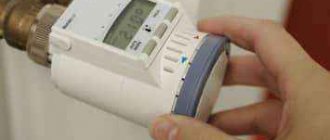
A magnetic starter is a device designed for switching power electrical circuits. The first thing you need to do before servicing or repairing a magnetic starter is to study the documentation for this starter, or, as they do in the 21st century, look it up on the Internet. It is also worth knowing the weak points of magnetic starters - contact groups. It is the contact groups that need careful examination. It is worth paying attention to the fastening elements and the body, which will be discussed in the article.
Visual inspection
Repair of a magnetic starter begins with an external inspection. An external inspection involves inspecting the body and fastening elements for cracks and chips. If there are cracks on the fastening elements, this affects the volume of operation, and also, if the starter falls off and its “toad” design, then there is a danger that it will turn on the power circuit. In addition, it is worth paying attention to protective covers.
It is also worth inspecting the starter for contamination. If there is a large amount of dust, oil, traces of liquid (crystalline growths) and other aggressive elements on the housing, then it is worth reconsidering the method of protecting the starter from aggressive environmental influences. Increase the degree of dust and moisture protection. If this is not done, the coil in the starter, which will be described below, will quickly become damp and fail, and the metal parts will become corroded.
Varieties
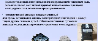
Magnetic starters are designed mainly to control the operation of 3-phase electric motors at a remote level. The main operations carried out using magnetic starters are starting, shutting down or reversing.
An auxiliary function of the starter, together with a thermal relay, is to protect the electric motor from excessive loads. There are starter circuits with voltage limiters based on semiconductor elements. According to the connection diagrams, loads can be reversible or non-reversible.
According to the type of location, magnetic starters are classified:
- Open type . Placed in protected cabinets, panels, and other places inaccessible to moisture, dust and other harmful factors.
- Secure execution . Installed in rooms with a low dust content in the air, preventing access of water to the device.
- Waterproof design . They are mounted inside buildings, outside under equipped canopies from water and sun.
Auxiliary classification:
- Block with buttons on the starter body. Starters without reverse have two buttons: Start and Stop, devices with reverse are equipped with three buttons, two of them are the same as in the previous version, a Start back button has been added. Some versions of the devices include a lamp indicating switching on.
- Devices with auxiliary contacts for signals and interlocks. They are used in various combinations, as closing or disconnecting. Contacts can be built-in or placed on a separate stand. Sometimes auxiliary contacts are used as part of the overall starter circuit. In devices with reverse, electrical interlocking is performed using additional contacts.
- The value of voltage and current of the power winding.
- Thermal relay. Its property is the nominal current at which the relay does not operate at medium settings. This current value can be adjusted within certain limits from the rated current value.
Contact groups
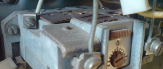
Basically, maintenance and repair of magnetic starters comes down to contact groups. To inspect them, you need to open the protective cover; the first thing we pay attention to is the contact groups. If there is slight carbon deposits, you need to clean it off with fine-grain sandpaper. As you can see in the photo, there is no oxidation. This means that the chosen method of protecting the starter from aggressive environmental factors is chosen correctly.
If traces of oxide, darkening, or rust are visible on the metal parts, then in this case it is necessary to definitely reconsider the method of installing the starter. Or rather, install it in a more dust- and moisture-proof shell. Then we inspect the contact groups for the presence of carbon deposits, deposits, and cavities. Depending on the degree of damage to the contact groups, a decision is made on repair or replacement.
Maintenance and repair of electromagnetic starters
⇐ PreviousPage 3 of 4Next ⇒
To prevent rapid wear and failure, maintain constant readiness for intended use, and ensure safe operation, maintenance (MOT) of starters is carried out. The types and regulations of maintenance and testing are determined by the Safety Rules (SR) and the Regulations on the planned preventive system of maintenance and repair of equipment of industrial enterprises (Regulations on PPR). Start-ups during operation should be periodically inspected:
a) persons working on technological machines, as well as
electric mechanics on duty, site electricians - every shift;
b) site mechanics or persons replacing them - weekly;
c) chief power engineer (chief mechanic) or persons appointed by him
- at least once every 3 months.
Shift inspection is carried out at the beginning of each shift without opening the starter casing. In doing so, check the following:
1. Place of installation of the starter, where possible
roof collapse, vehicle damage, water ingress. The starter must be assembled and equipped in accordance with the manufacturer's instructions.
2. Cleanliness of the external surfaces of the starter, i.e. the absence of
coal dust and other flammable material.
3. Shell integrity. The explosion-proof enclosure must not have cracks,
burns, holes, faulty protective glass and other damage.
4. Availability of fastening nuts and bolts, their tightening. Nuts and bolts must be fully tightened so that the flanges of the roofs and flameproof enclosures fit snugly around the entire perimeter. It is prohibited to operate the starter if at least one bolt or nut is missing or insufficiently tightened.
5. Serviceability of input devices, presence of sealing elements and cable fastenings. The cable must not rotate or move axially. Loose bolts or nuts designed to seal the rubber ring and secure the cable from being pulled out must be tightened.
6. The absence of cable inputs of the starter that are not closed with an explosion-proof plug and are not used in operation.
7. Serviceability of devices to facilitate opening the lid and the presence of special keys for them.
8. The presence of seals on the starters and inscriptions indicating the technological machine being switched on, the value of the current setting for maximum current protection and maximum current overload protection.
9. The width of the gap (gap) in flat joints between the outer parts of the shell that was opened, with normal tightening of the fastening bolts.
A quarterly inspection is carried out by opening the covers of the explosion-proof enclosure, disassembling the inputs (if necessary), inspecting all electrical elements of the starter and performing the necessary technical repairs. Before the inspection, you should: use the nearest switch to remove the voltage from the starter being inspected and hang a poster on its handle “Do not turn on, people are working”; open the cover of the starter's input compartment and make sure there is no voltage.
10. Cleanliness of the internal surfaces of the shell. To do this, open all covers of the shell and, if necessary, clean the surface and installed elements of the starter from moisture and dust. The box input is removed if necessary.
11. Condition of explosion-proof surfaces. If there is contamination, clean the surface with a rag to remove grease and dust, and sandpaper to remove rust.
12. Presence and condition of elastic sealing gaskets (if provided for by the starter design). Wrinkled or torn gaskets must be replaced.
13. Quality of seals of flexible and armored cables when dry termination of the latter.
14. Serviceability of guard rings for the heads of fastening bolts and nuts.
15. The quality of tightening of the cable cores connected to the clamps and the condition of these clamps. Loose nuts or bolts are tightened, insulating bushings that are chipped or cracked are replaced.
16. Condition of installation of internal wiring and starter elements: nuts and bolts on the terminals are tightened, damaged areas of conductor insulation are insulated, and if necessary, the conductor is replaced.
17. The serviceability of the mechanical locking of the lid, which should work clearly and reliably.
18. Condition of inspection windows. Windows are checked without disassembling, paying attention to the integrity of the glass and the presence of fasteners on them and their tightening.
In the conditions of intense work of enterprises, repair of electrical equipment must be carried out in an extremely short time, which is possible with a high level of organization of repair work. Since the needs of enterprises for transformers, electrical machines and apparatus are not yet fully satisfied, timely and high-quality repairs of this electrical equipment have become one of the main factors ensuring the normal operation of enterprises.
During the repair process, it is possible to modernize electrical equipment, change its technical characteristics in the right direction, and increase operating efficiency. Long-term practice of electrical repair shops of enterprises and electrical repair plants has shown that over 70% of damaged electrical equipment received for repair are transformers, electrical machines and switching devices, in the repair of which electrical plumbing work plays a significant role.
In my work, I examined the issues of maintenance and repair of magnetic starters
Maintenance
During the period between repairs, maintenance of electrical devices is carried out, which is a set of operations or an operation to maintain the functionality or serviceability of the device during intended use, standby, storage and transportation. The device is not disassembled.
The typical scope of maintenance work for magnetic starters includes: cleaning dust and dirt, lubricating rubbing parts, eliminating visible damage, tightening fasteners, cleaning contacts from dirt and deposits, checking the serviceability of casings, shells, housings, checking the operation of signaling and grounding devices .
Repair work
As a result of operation, accidents, overloads and natural wear and tear, some electrical equipment and networks fail and must be repaired.
Repair is a set of operations to restore the serviceability or performance of electrical devices, restore their resources or their components. A repair operation is understood as a completed part of a repair performed at one workplace by performers of a certain specialty, for example: cleaning, disassembling, welding, making windings, etc.
In electrical devices, moving, fixed and arcing contacts are most often damaged. Repair mainly consists of identifying the malfunction, eliminating it, replacing damaged and worn parts, followed by adjustment and testing. During operation, the contacts are cleaned of metal deposits, soot, and oxides. Clean with a file with a fine (fine) notch. Eliminates strong and weak contact pressure. To do this, place paper (foil) between the contacts, pulling the movable contacts through a dynamometer and pulling out the foil. Normal force is 0.5-0.7 kg. The magnetic contact system can create noise, humming, the reasons for this are: the armature does not fit tightly to the core, damage to the short-circuited turn, very high contact tension, the armature is skewed in relation to the core, there is rust in places where the armature and core touch, magnetic starters and contactors should not be allowed different times of closing power contacts.
Short-circuited turns for contactors and magnetic starters are made of copper, brass and aluminum. They fit into stamped grooves at the ends of the core. Attention is drawn to arc chutes. Their absence can cause the arc to overlap individual phases. Coils are repaired in case of frame damage, breaks, turn short circuits and complete combustion. A break in the coil is detected if no traction force is developed and no current is consumed. A turn fault is detected by abnormal heating and decreased thrust.
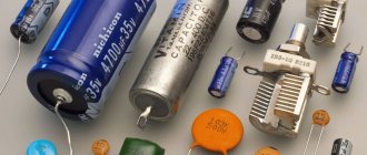
For contactors, main contacts, flexible connections, arc chutes, coils, springs, and short-circuited turns are often replaced. The insulation resistance of the windings should not exceed 0.5 MOhm. The heating elements of the relay burn out more often. Nichrome and fechral are used for heating elements. Individual heating elements are made by stamping. Spiral heating elements are cadmium coated to protect against oxidation. Figure 6 shows the magnetic starter contactor.
Contact repair. Contamination, wear, burning, soot or oxidation, deposits and splashes of metal on the surface of moving (including knife switches) or fixed (knife jaws) contacts, as well as on plates and contact bridges, are eliminated with a cotton napkin soaked in gasoline or a file.
If the contact springs are broken or weakened, or the anti-corrosion coating is damaged, the springs are replaced.
Repair of electromagnet coils. Reels can be framed or frameless. The most common damage is cracks up to 15mm long in the frame. They are eliminated as follows. The surface of the frame around the crack is cleaned of dust and oil with a cotton cloth soaked in gasoline.
If the outer layer of the coil insulation is damaged or the winding wire breaks in the upper layers of the winding, remove the outer insulation of the winding and the damaged turns to the point of damage or breakage, solder, insulate the soldering area of the new winding wire and wind the required number of turns, repeating the operations that are performed when winding new coils .
In case of significant damage to the frame, interturn short circuits, or burning of the winding insulation to a great depth, the coil must be replaced with a new one.
Repair of frame reels. Select the frame and wire required for the coil, the parameters of which must correspond to the passport data. Before installation on the winding machine, the frame should be wrapped in a double layer of electrical insulating paper with a thickness of 0.02-0.03 mm and the end should be glued to the frame. When winding, you must ensure that the tension on the wire is not excessive, as this may cause the wire to break. When winding, the wire should lie in an even, dense layer. Between the 1st and 2nd layers of the winding, interlayer insulation made of insulating paper is laid. If the coil is heat-resistant, then thin fiberglass fabric is used for interlayer insulation.
Repair of magnetic circuit. Contaminants are removed with a cotton cloth soaked in gasoline; traces of corrosion are thoroughly cleaned with a steel brush and sandpaper; hardening on the contact surfaces of the core and yoke is removed by grinding the surface with a file on a grinding machine.
⇐ Previous3Next ⇒
Recommended pages:
Use the site search:
Example of faulty moving contacts that must be replaced
The photo above shows a contact that “survived” after a short circuit. The remaining two have failed and need to be replaced.
Repair of contactors and magnetic starters often comes down to repair of contact groups. This is done by cleaning carbon deposits from the contact pad. If shells and build-ups are found during inspection, then these places need to be leveled with a flat, small file or needle file. This is done in the same plane as the contact pad of the fixed contact. To ensure a better effect, you can grind both contact pads on the moving and fixed elements.
It is highly not recommended to do all these operations with sandpaper or sandpaper, since in this case it is very difficult to maintain a flat surface. An unmaintained plane means a decrease in the contact area, and this in turn causes excessive heating and premature failure of the magnetic starter. It is worth inspecting both the main and auxiliary contact groups.
Contact block or contact attachment.
A movable contact system is built inside the contact block (contact attachment), which is rigidly connected to the contact system of the magnetic starter and becomes one with it. The attachment is attached to the top of the starter, where special skids with hooks
.
The contact system of the set-top box consists of two pairs of normally closed
and two pairs
of normally open
contacts.
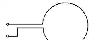
To go further, let's immediately understand: what are normally closed and normally open contacts. The figure below schematically shows the button
with a pair of contacts numbered
1-2
and
3-4
, which are fixed on a vertical axis.
The right side of the figure shows a graphical
representation of these contacts used on electrical circuit diagrams.
Normally open (NO)
The contact in the non-working state is always
open
, that is, not closed.
In the figure it is indicated by a pair 1–2
, and in order for current to pass through it, the contact must
be closed
.
Normally closed (NC)
When not in use, the contact is always
closed
and current can flow through it.
In the figure, such a contact is indicated by a pair 3–4
, and in order to stop the flow of current through it, the contact must
be opened
.
Now, if you press the button, the normally open contact 1-2 will close
, and the normally closed 3-4
will open
. This is what the picture below shows.
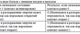
Let's return to the contact block. In the initial state, when the magnetic starter is de-energized
, normally open contacts
53NO–54NO
and
83NO–84NO
are open, and normally closed contacts
61NC–62NC
and
71NC–72NC
are closed. This is indicated by a nameplate with the numbers of the contact terminals located on the side wall of the contact block, and the arrow shows the direction of movement of the contact group.
Armature and electromagnet
The armature and magnetic circuit of a magnetic starter rarely suffer, but sometimes it happens that the package in which the sheets of cold-rolled anisotropic electrical steel are collected crumbles. This is usually caused by a manufacturing defect. But this happens extremely rarely.
The most common damage that occurs when repairing a magnetic starter on the armature and magnetic circuit is corrosion. Switching is carried out by moving the armature downwards under the action of an electromagnet and upwards under the action of springs. As a result of the vibration created, rust flakes off and can accumulate in moving parts, which can jam over time.
Springs, mounting bolts and screws
Springs and bolts should be inspected for corrosion. Springs lose their properties over time, which means they must be replaced. A bad spring causes the load to be released slowly, which means that the arc created during the release process will act on the contact groups longer, which will accelerate their wear. You should also not install an overly strong spring.
This will lead to incomplete closure of the magnetic flux, which will cause additional heating of the coil, and this in turn will damage it. Bolts and screws with signs of severe corrosion must be replaced. It is also worth inspecting the threaded connections. Threads on bolts that have been lapped, damaged by corrosion or mechanically damaged must not be used; such bolts must also be replaced.
Magnetic starter coil
When the magnetic starter coil is pulled out from its place, the first step is to inspect its section (the frame on which the copper wire is wound) for cracks and chips. In our case, the copper wire is filled with plastic. If there is damage, the starter will make a lot of noise during operation. Then you need to pay attention to the coil itself. There should be no traces of heating (blackening) on the paper/plastic, and there should also be no burning smell. Typically, the main data is indicated on the side of the reels.
This is the number of turns, operating voltage, type of current (if alternating, then frequency). The brand and thickness of the wire and the brand of the starter for which it is intended are also indicated. Determining the presence of an interturn short circuit is quite difficult. For example, by abnormally low or high resistance. If the reel looks the same as in the photo above, then it can be rewound. If it is filled with plastic, it must be replaced.
Features of connecting 380 V devices
The choice of type and connection diagram for a magnetic starter depends on the properties of the electrical installation and the conditions of its use. Connecting electrical devices to a three-phase voltage of 380 V has become widespread.
In this case, a signal of 220 V is supplied to the control choke. Based on the conditions and needs, connection options are selected.
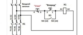
- In the simplest connection options there are two buttons: to turn on - “Start”, to stop - “Stop”. They are manufactured separately with their own contacts, in one housing in the form of a push-button post.
- Regardless of the external design, the buttons have two sets of contacts: start and stop. The appearance is complemented by a grounding terminal. The winding terminals are designated A1, A2, the incoming terminals are L1-L3, the outgoing terminals to which the electrical installation is connected are T1-T3.
- A control voltage of 220 volts is supplied to terminals A1, A2. It does not matter which terminal the neutral or phase wire is connected to. To prevent the contacts of the device from being energized all the time, a plug is connected to them in everyday life.
- Power is supplied from the outlet. It is possible to connect the control circuit through a clock relay, temperature controllers, and luminous flux level controllers.
To ensure that the control circuit does not open after the start button returns to its initial state, the circuit uses the pick-up itself.
It is implemented using auxiliary pins (indicated by numbers 13, 14), connected in parallel to the start button circuit. Shutdown occurs by activating the stop button, from a signal from a thermal sensor, a decrease, or absence of voltage in the external line.