The push-button station is designed for switching circuits designed to control alternating current, the voltage of which is up to 660 V with a frequency of 50 and 60 Hz. In addition, they can be used in DC circuits with voltages up to 440 V or for supplying control signals. The latter can be performed either remotely or on site.
Typically, such products are needed to control devices of various types at a distance.
The design of the control panel is quite simple , there are a minimal number of parts in it, but there is one very important function - to issue commands and check how completely they have been executed.
They are used in automatic systems, in particular, such devices can be placed in metal and woodworking machines, various types of mechanisms aimed at lifting and moving loads.
Its body is usually made of plastic, there are at least 2 control elements, but there can be much more.
Its pusher is mushroom-shaped or made in the shape of a cylinder. Cylindrical products are available in black, white, yellow, red, blue or green. The mushroom-shaped pusher is painted red or black.
The contact elements operate via both the making and breaking principles.
Explosion-proof models are used to remotely control electric drives of stationary or mobile installations. These devices can be used in the gas and oil industries, as well as in other types of industrial production.
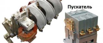
magnetic switch
This system is quite flexible and is equipped with several modules, as well as a magnetic starter. The latter is connected directly through a push-button post, due to which the reliability of its operation becomes very high.
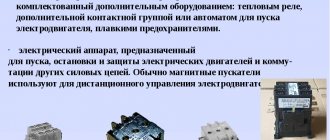
This starter is a switching structure, due to which electricity is disconnected or connected.
Such starters have a metal or plastic body and can be used in direct or alternating current networks. They are often used in automated systems and devices; in addition, they are designed to turn systems on or off in the event of an emergency.
They can be remote or built directly into the design of the product.
Device and design
The standard push-button control station has the following design features:
- Each of the buttons does not have a fixed position.
- The “Start” button is usually painted green, and sometimes even backlit when turned on; it also has normally wired contacts; it itself is used to activate the operation of a particular mechanism.
- The “Stop” button is usually red and is located on closed contacts. Due to this, the supplied voltage is removed from the device and its operation is suspended.
- In addition , push-button control stations can have a metal or plastic body. Each of them has its own level of protection. They are allowed to be used in devices intended for distribution purposes, as well as in the automation of most industrial systems.
- The push-button station is the basis of the design of most remote controls; it is directly involved in turning the equipment on or off, and acts in an emergency.
If the equipment is dangerous to human life or health, similar devices are produced with an increased degree of protection. The connection diagram in this case is much more reliable, and the remote control itself can be connected to various devices.
Often, the installation is controlled from 2 points. As a rule, this is caused by a certain production need. Typically, various electric motors operate using this technology, but other equipment can also operate.
How to connect a three-phase motor via a magnetic starter
Power supply 380 V (three phases) is carried out in the same way, only there will be more power wires.
The contactor includes not one, but three phase lines. In this case, the control button is connected according to a similar circuit (as in the single-phase case).
The illustration shows a starter with a 380 V solenoid control coil. The control circuit is switched between any two phases. For safety, there is a thermal relay, the sensors of which can be located on one or several phase wires.
How to connect a 3-phase contactor with a 220 V starter winding? The circuit is similar, only the control circuit is switched between any of the phases and the neutral wire. The thermal relay works just as accurately, since its mechanism is tied to the temperature of the power cables.
Operating principle
Such a device is a switching device, thanks to which the electric current is controlled and distributed along the circuits to which it is connected.
On the one hand, at the push-button station there are power contacts, which perform switching on, switching, normal and emergency shutdown of the equipment.
On the other hand, an electromagnetic coil is installed, due to which these contacts are switched on and off:
- In the first part, these power contacts, as a rule, are movable and are located on a dielectric traverse. If these elements do not have such a characteristic as mobility, then they are placed directly on the body, which must also be dielectric. With their help, power lines are connected. In a calm state, such contacts are open, and no electric current flows through them. There is no load on them in this state. They are held in this state thanks to a special spring;
- The second part is equipped with an electromagnetic coil. Until a sufficient amount of voltage is applied to it, it is also at rest. When the voltage increases, an electromagnetic field appears on the coil circuit, creating an electromotive force. Due to it, a movable core or armature with power contacts attached to it approaches the coil. As a result, the circuits connected through them are closed and a workload is formed.
- When the voltage is removed from the coil , the electromotive force disappears, and the armature cannot be held in the active position; under the action of the spring, it has to return to its original position. As a result of this, the power contact circuits open and the installation stops working.
Degree of protection
Devices with a degree of protection IP54 perform best. They can be used in damp and very dusty areas. You can install it in an open place without any problems. But if installation is carried out inside a cabinet, then it is enough to use devices with a degree of protection IP20. The higher the numerical index, the more severe the conditions under which the device can be operated - this applies to any electrical device. The following factors must also be taken into account:
- The presence of a thermal relay, with the help of which the load is switched off when the maximum current consumption is exceeded. The use of such a device is especially important when controlling electric motors.
- If there is a reverse function, then the design has two coils and six contacts. Essentially, these are a pair of starters combined in one housing.
- It is imperative to take into account the wear resistance of the device, especially if the load is turned on and off by the starter very often.
Not least in the operation of any device, including a 220V electromagnetic starter, is the human factor. Unskilled workers can break the entire control chain because they do not know how to operate the equipment correctly. If the thermal protection has tripped, it cannot be switched on immediately. And you cannot restart the engine - first you need to check whether the motor is jammed or whether there is a short circuit in the power circuit.
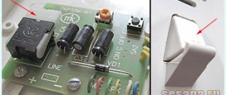
Usually we see this device in the form of a neat box with two buttons: “start” and “stop”. If you remove the top cover, inside you will find a switch of a rather complex design that can perform several tasks (both in turn and simultaneously).
This is an electromagnetic starter. The question arises: why create complex electrical devices if you just need to close two (or more) contacts? There are buttons with fixation, lever switches, circuit breakers, switches. Let's consider a typical application of a magnetic starter: turning on a powerful electrical installation (for example, an asynchronous electric motor).
- A powerful contact group with arc extinguishers is required; accordingly, a lot of force is required to close the contacts. A manual drive will be quite cumbersome (using a classic switch does not always fit into the aesthetics of the workplace).
- It is difficult to quickly change the operating mode with manual switches (for example, changing the direction of rotation of the motor). The magnetic starter device allows you to assemble such a connection diagram.
- Organization of protection. Any machine with an emergency shutdown is not designed to be turned on multiple times. The purpose (albeit not the main one) of a magnetic starter is not only to repeatedly switch, but also to disconnect the power circuit in case of overloads and short circuits. At the same time, it has an undeniable advantage over other switches. The shutdown is irreversible: that is, after an emergency opening of the contacts, or a momentary loss of power, the operating contacts do not return to the default “ON” position. The principle of operation of the magnetic starter implies only forced restart.
Advantages
The main positive aspects of its operation are:
- The configuration of the device can be standard or tailored to the specific requirements of the direct customer.
- The body is made of non-flammable materials - special refractory fire-resistant plastic or metal.
- Between the cover and the body there is a small gasket made of rubber, which creates a good seal.
- The push-button post implies the possibility of installing 2 light indicators - one for each control button.
- The structure's seal is well protected from the negative effects of environmental factors.
- on the side of the structure through which the cable is inserted.
- All fasteners are made of stainless steel - grade 316 steel, which makes the fastenings of this device quite reliable.
Largely due to all these advantages, push-button posts have one of the highest degrees of protection.
Main types:
Typically used when working with woodworking devices for both industrial and domestic purposes.
Used in industry where there is no threat of explosion, and the total concentration of dust or gas will not lead to failure of such equipment.
Used when working with electrical equipment installed on mechanisms capable of lifting large loads, for example, beam cranes, overhead cranes, and so on. With the help of such a device, the tool will be controlled from the surface of the earth in manual mode.
Technical characteristics and operating conditions
Despite the huge variety of models available for sale, their technical characteristics are the same, but may differ slightly in parameters:
- Rated voltage (in the case of alternating current – up to 660V, with direct current – up to 440V).
- Lowest operating voltage (with alternating current - from 36, with direct current - from 24).
- Rated voltage across the insulating layers (up to 660V).
- Rated current (10A).
- Through current flowing through the push-button post for one second (200A).
- Nominal operating mode (there can be 4 types: short-term, intermittent, long-term and intermittent-long).
Operation largely depends on the type of control station, but there are a number of general points:
- First of all , the push-button post should not be located above 4300 m above sea level.
- The temperature in a workshop or other work area can be from -40 to +40 degrees.
- If the humidity regime exceeds 80% at a temperature of 20 degrees, then this will soon lead to damage to the contacts; at a temperature of 40 degrees, this figure should not exceed 50%.
- There are devices capable of operating in explosive environments, but most models are not designed for this.
- In addition , the environment should not contain large amounts of dust capable of conducting electric current, corrosive gas and water vapor.
- to expose the structure to direct sunlight.
Definitions and purposes of basic terms
Toggle switches are compact manual switches that are designed for switching low-voltage AC and low-power DC circuits. The use of toggle switches is justified in situations where there is no need to frequently switch the device, in stationary and mobile devices.
Typically, such devices have a small number of characteristics, some of which are not technical. The latter include the name of the post, its type and a note on the device.
They may also have the following technical parameters, according to which they are selected:
What kind of lighting do you prefer?
Built-in Chandelier
- rated current in amperes (usually 6 A);
- voltage in volts (220, 250 V and more);
- design option according to the type of control element;
- number of electrical contact elements;
- climatic characteristics according to the relevant GOST.
Note! Control elements can be of the following types: cylindrical, mushroom-shaped, mushroom-shaped with fixation in the “pressed” position, cylindrical with a lock and fixation.
You might be interested in Features of a wind generator for home
Model overview
Push-button station PKE 222-3-U2-IP54-KEAZ
It has 3 buttons, is placed in refractory plastic, meets all state standards GOST 15150-69 and GOST 15543.1-89.
Its price is 237 rubles.
Push-button station Electrician PKU 15-21
It has 2 buttons, an LED activity indicator, is housed in an aluminum case, and has all the necessary certificates of conformity.
Costs 1248 rubles.
Hanging push button station Schneider Electric Harmony XAC-B XACB6913
The starter is designed for starting, installing and reversing three-phase asynchronous electric motors with a squirrel-cage rotor, as well as protecting them from overcurrents of unacceptable duration.
As an element of automatic control systems, electromagnetic starters are subject to high wear resistance requirements. Wear resistance classes: A, B and C. Starters are produced in versions with varying degrees of protection from touches and external influences (IP00, IP20, IP40, IP54). Climatic modification and placement categories according to GOST 15150-69 and GOST 15543.1-89.
Installation is carried out on a vertical surface using mounting screws, with an inclination of no more than 15 degrees. The altitude above sea level is no more than 2000 meters (when placed at an altitude of 2000 meters to 4300 meters, the rated current of the starter is reduced by 10%).
Connection
In most cases, a push-button station is used to switch the power supply to magnetic starters that are installed in the control circuits of asynchronous AC motors.
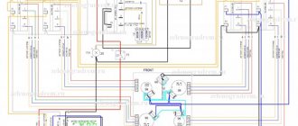
and controlling it using a three-button post is shown in the figure above, where the following notations are adopted:
- “Start forward/backward” and “Stop” are buttons on the control panel.
- KM1 and KM2 are coils of magnetic starters that perform direct and reverse activation of the electric motor.
- KM1.1…KM2.3 contacts of magnetic starters.
The scheme works as follows:
- When you press the push button “Start-forward” , power is supplied to the coil of the first magnetic starter (“KM1”); the group of normally open contacts KM1.1 closes, supplying power to the motor windings.
- Normally closed contacts “KM1.2” disconnect the pusher contacts “Start-backward”, blocking the activation of the coil of the magnetic starter “KM2”, and normally open contacts “” close parallel to the “Start-forward” button.
- When you press the “Stop” pusher, power is not supplied to the coils of both magnetic starters (“KM1”; “KM2”), they are turned off, the contacts “KM1.1” and “KM1.3” open, de-energizing the electric motor.
- When you press the “Start-Reverse” button, the contact closure procedures are similar, only they are carried out in relation to the second magnetic starter “KM2”.
Reversible circuit for connecting an electric motor through starters
In some cases, it is necessary to ensure that the motor rotates in both directions. For example, for the operation of a winch, in some other cases. A change in the direction of rotation occurs due to phase reversal - when connecting one of the starters, two phases must be swapped (for example, phases B and C). The circuit consists of two identical starters and a button block, which includes a common “Stop” button and two “Back” and “Forward” buttons.
Reversible diagram for connecting a three-phase motor through magnetic starters
To increase safety, a thermal relay has been added, through which two phases pass, the third is supplied directly, since protection in two is more than enough.
Starters can be with a 380 V or 220 V coil (indicated in the specifications on the cover). If it is 220 V, one of the phases (any) is supplied to the coil contacts, and “zero” from the panel is supplied to the second. If the coil is 380 V, any two phases are supplied to it.
Also note that the wire from the power button (right or left) is not fed directly to the coil, but through the permanently closed contacts of another starter. Contacts KM1 and KM2 are shown next to the starter coil. This creates an electrical interlock that prevents two contactors from being supplied with power at the same time.
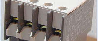
Magnetic starter with a contact attachment installed on it
Since not all starters have normally closed contacts, you can take them by installing an additional block with contacts, which is also called a contact attachment. This attachment snaps into special holders; its contact groups work together with the groups of the main body.
The following video shows a diagram of connecting a magnetic starter with reverse on an old stand using old equipment, but the general procedure is clear.
Design features
Depending on the number of controlled electricity consumers, the posts can be two-button ("Start" and "Stop" pushers) and multi-button. In addition, when performing electrical and electrical work, single buttons are used, which the user can independently install on any control panel.
Push-button stations are mounted in a plastic or metal case that has mounting holes for installing the fittings in a place convenient for use. A separate group consists of push-button stations designed to control hoists (PKT series), beam cranes and overhead cranes with ground control.
The main functional element of the device that starts, stops or switches the modes of the electricity consumer is a push button - an electrical switching fixture with manual control.
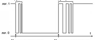
Today, control panels use two types of pushers:
- With self-return , in which the button returns to its original state due to a return spring installed on the pusher on the bottom side.
- Pushers with position fixation (self-holding), which close the contact and hold it until pressed again.
The most common is a two-button starting valve, the design of which is shown in Fig. 2. The remote control consists of a housing 1 and a front panel 2, which are connected to each other by screws 3. The buttons are painted in different colors and control a pair of contacts located inside the housing.
Using a magnetic starter
Before connecting the starter, you need to understand its structure. The electromagnetic starter (MP) itself is a relay, but it is capable of switching a much larger current. This ability is due to large contacts, as well as response speed. For this purpose, the device has more powerful electromagnets.
An electric magnet is a coil containing enough turns of insulated wire to carry a current ranging from 24 to 660 volts. The coil is located on the core, which allows you to increase the magnetic flux. This power is needed to overcome the force of the spring and increase the speed of contact closure.
The spring is installed to quickly open the contacts. The faster the opening occurs, the smaller the electric arc will be. An electric arc is harmful because it creates a very high temperature, and this has a detrimental effect on the contacts themselves. More powerful devices - contactors - are also equipped with an arc-extinguishing chamber, which allows you to break the circuit with an even higher current (on powerful contactors up to 1000 A, for MP - from 6.3 A to 250 A).
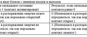
Although the starter control coil is powered by alternating current, any type of current can be passed through the contacts. Unlike contactors and relays, MPs have two groups of contacts:
- power;
- blocking
Power contacts are used to connect the load, and blocking contacts serve to protect against incorrect or dangerous connections. Depending on the design, there may be three or four pairs of power contacts. Moreover, each pair contains movable and fixed contacts. The latter are connected through metal plates to terminals located on the housing. Wires are connected to them. Blocking contacts can be:
- normally closed;
- normally open.
Types of push-button control panels
Today, on the electrical equipment market, a fairly large number of different push-button remote controls are produced that control electrical equipment.
However, functionally and structurally, they are all identical and differ in design and brand. All model lines of this type of electrical fittings can be supplied in various placement categories and different designs.
Typically, these two parameters are reflected in the symbol of a specific model. Russian enterprises produce the PKE, PKT and PKT series for installation in industrial equipment control systems.
The PKE series has found the widest distribution in control circuits of wood and metalworking machines and industrial complexes.
The permissible operating parameters of these devices are as follows:
- Maximum value of switching voltage: constant – 400.0 volts; alternating (frequency 50.0 or 60.0 hertz) – 660 volts;
- Switching current – 10.0 amperes;
- Maximum number of actuation cycles – 5×10 6 .
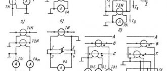
The symbol for push-button stations of the PKE series is shown in Figure 3, in which the following characteristics are indicated by numbers:
- 1 – serial number designation;
- 2 – characteristics of the installation method (built-in or overhead);
- 3 – degree of protection category;
- 4 – body and panel material (metal or plastic);
- 5 – number of controlled contacts (the figure shows the designation for two contacts);
- 6 – a parameter indicating product modernization;
- 7 – category of accommodation and the corresponding climatic modification.
Rice. 4. Designation of the “PKU” series
Posts of the PKU series are intended for operation in an explosion-proof environment where the concentration of dust or gas will not impair their functionality.
The fittings have operational parameters similar to the PKE model line, however, the manufacturer has provided its own designation for this electrical fittings, which is shown in Figure 4.
The digital designations shown in the figure correspond to the following parameters, which allow you to characterize a specific device model:
- 1 – serial number designation;
- 2 – serial modification number;
- 3 – rated current switched by contacts of a separate button;
- 4 – the number of pushers installed in horizontal rows;
- 5 – the number of pushers installed in vertical rows;
- 6 – installation method (overhead, built-in or suspended);
- 7 – degree of electrical protection;
- 8 – category of accommodation and the corresponding climatic modification;
Fig.5 – PKT remote control
The PKT series is designed to work with electrical equipment of lifting mechanisms (electric hoists, overhead cranes and overhead cranes) with ground-based, manual control.
Operational and electrical parameters are similar to devices of the “PKE” and “PKU” series. Under the abbreviation “IEK”, Chinese fittings are sold on the Russian market of electrical products, whose characteristics are completely similar to Russian control posts.
The general view of this electrical fittings is shown in Figure 5.
In the designation “PKT-X1 X2 X3” the digital indices characterize the following parameters:
- X1 – series number;
- X2 – number of control buttons;
- X3 – placement category and corresponding climatic modification.
Explosion-proof starting fittings
Russian explosion-proof valves have in their letter designation an additional index “B” - “PVK”, or “KPVT”. They are most widespread in control circuits for electrical equipment operating in explosive environments in coal mines, oil storage facilities, paint shops and other similar facilities.
Hoist push-button controls “HAS-A” (“Schneider Electric” - Germany) and “KS” (“SN Promet” - Poland) are widely used. In addition, remote push-button control valves are becoming increasingly common in this category.
Cost indicators
The cost of Russian push-button posts is quite low and depends primarily on the number of buttons , category of placement and climatic design. Devices in a metal case are slightly more expensive than analogues installed in a plastic case.
For example, the price of two-button devices “PKE-222-2” is in the range of 250.0...280.0 rubles. A similar device with a mushroom-shaped “Stop” button will cost a little more – 380.0 rubles.
The price of one-button posts does not exceed 150 rubles. The six-button telpher remote control “PKT-60” costs 300.0 rubles. A device with a similar number of buttons and electrical parameters, equipped with a key (“foolproof”), will cost 200.0 rubles more.
>