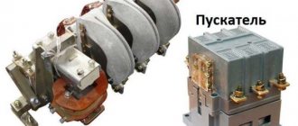
An electromagnetic starter is a device that is very often a component of electrical circuits. As a rule, a 380V three-phase electromagnetic starter is used in electric motor control circuits. However, in addition to switching electric motor circuits, the same element can be successfully used for other purposes.
Let's consider a typical device and operating principle of an electrical appliance. In addition, we will outline the criteria for choosing a starter, decipher its markings and describe the nuances of connecting an EMF to an electrical circuit.
Types of magnetic starters
Depending on the voltage value in the executive, control circuit - 220 V, 380 V; depending on the type of circuits: single-phase, three-phase; from the connected power: for controlling low power motors - 1-10 kW, medium power - 10-100 kW, large motors - 100-1000 kW, powerful electric motors - more than 1 MW.
They produce several series of starters, each of them has its own purpose and design features.
- The most common starting devices are the PME, PMA, PML, PM, PA series.
- In all designations, the letter “P” stands for “starter” and “M” stands for “magnetic”.
Products of the PME series are used to control low-power motors, the PA, PAE series are used to start medium-power motors, the PMA, PML series are used to operate control circuits for asynchronous motors with power up to 90 kW.
Differences between a relay and a contactor
Relays differ from contactors only in design and purpose, and the difference between them is sometimes barely distinguishable.
Usually,
- The relay does not have arc chutes.
- The relay is housed in a sealed housing.
- The relay is designed for low current and purely resistive loads.
- The relay has switching contacts, which means normally open and closed.
- The relay is not designed to connect a reactive three-phase load.
- A relay can have from 1 to 6 equivalent contacts, and a contactor must have 3 power and (as an option) 1-2 low-current contacts.
- The relay does not have additional functions or contacts, and the contactor can be supplemented with attachments for various installations and purposes.
- The relay is mounted on the panel and can be easily replaced using just your hands. In order to replace the contactor, you need to de-energize the equipment and use a screwdriver.
Learn more about what a relay is and what it is needed for in the video:
Design features of starters
In the photo of the magnetic starter in the disassembled position, the largest parts are clearly visible: housing, magnetic circuit, coil, contacts, return spring. The body is collapsible, divided into two parts connected with screws.
- Made of non-flammable, refractory dielectric material. One part of it is a removable molded cover.
- It is divided into three cavities according to the number of closed contacts.
To reduce the negative impact of self-induction currents that occur when contacts open, the design of the magnetic starter includes ribbed electric arc absorbers. They are located in each section of the lid.
An important part of the starter is the magnetic circuit. It consists of movable and fixed parts. Made from a set of electrical steel plates. The plate structure prevents the occurrence of Foucault currents, reduces heating, but does not interfere with the flow of magnetic flux. The plates are shaped like the letter “W”.
The part of the magnetic circuit located at the bottom is stationary, rigidly fixed at the base, the upper part moves; there are movable contacts on it. They come in two types: normally closed, open; When a pulse arrives, open contacts close, and closed contacts break the circuit. The coil is installed in the grooves of the lower part.
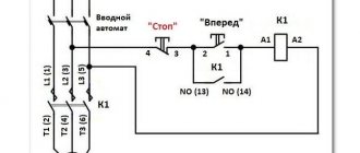
Reversible connection of a three-phase motor
When the switch QF1 is operating , simultaneously all three phases, without exception, are adjacent to the contacts of the starter (KM1 and KM2) and are in this state. In this case, the first stage, which represents power for the control circuit, flowing through the protection device of the control circuit SF1 and the shutdown key SB1, directly supplies voltage to the contacts under the third number, which refers to SB2, SB3. In this case, the existing contact 13NO takes on the role of the main duty officer. In this way, the system is considered completely ready for operation.
System switching during counter rotation
By using the SB2 key, we direct the first phase voltage to the coil, which relates to the KM1 starter. After this, normally open contacts are introduced and normally closed contacts are turned off. In a similar way, by closing the existing contact KM1, the effect of self-capture of the magnetic device occurs. In this case, all three phases, without exception, are supplied to the required winding of the motor, which, in turn, begins to generate rotational movement.
The created model provides for the presence of one working device. For example, only KM1 or, on the contrary, KM2 can function. The marked chain has real elements.
Changing the turning movement
Now, to give the opposite direction of movement, you should change the state of the power phases, which is convenient to do using the KM2 switch. Everything is accomplished thanks to the opening of the first phase. In this case, all contacts without exception will return to their original state, de-energizing the motor winding. This phase is considered standby mode.
Using the SB3 key activates the KM2 electromagnetic starter, which in turn changes the position of the second and third phases. This influence forces the motor to rotate in the opposite direction. Now KM2 will be the leader, and until it is disconnected, KM1 will not be used.
How does the starter work?
In the standby state, the control circuit is de-energized, the contacts of the starting device are held at a short distance by springs.
The principle of operation of the starter is as follows.
- After pressing the start button, current flows through the coil winding, and a magnetic field appears around it, reinforced by the magnetic circuit.
- This part of the starter acts as an electromagnet: It attracts the moving part of the core along with the contacts.
- When the button is released, the control circuit does not open, the electromagnet reliably holds the contacts of the supply circuit in the closed state, and the engine runs.
When the shutdown button is activated, the throttle control circuit opens, the magnetization of the magnetic circuit decreases, and the springs open the contacts.
Design of a reversible magnetic motor
The distribution of these modifications is becoming more widespread every year, as they help control an asynchronous motor at a distance. This device makes it possible to both turn on and off the motor .
The reversing starter housing consists of the following parts:
- Contactor.
- Thermal micro relay.
- Casing.
- Management tools.
After the “Start” command has been received, the circuit is closed. Next, the current begins to be transmitted to the coil. At the same time, a mechanical blocking device operates, which prevents unnecessary contacts from starting. It should be noted here that the mechanical lock also closes the contacts of the key, this makes it possible not to keep it pressed constantly, but to calmly release it. Another important part is that the second key of this device, together with the start of the entire device, will open the electrical circuit. Thanks to this, even pressure produces virtually no result, creating additional safety.
Features of the model's functioning
Pressing the Forward key activates the coil and makes contacts. At the same time, the operation of the start key is performed by constantly open contacts of the KM 1.3 device, due to which, when the key is directly released, the power to the coil acts bypass.
After introducing the first starter, it is the KM 1.2 contacts that open, which turns off the K2 coil. As a result, when you directly press the “Back” key, nothing happens. In order to turn the motor in the opposite direction, you need to press “Stop” and turn off the power to K1. All blocking contacts can return to the opposite state, after which it is possible to drive the motor in the opposite direction. In the same way, K2 is introduced and the block with contacts is turned off . Coil 2 of starter K1 is turned on. K2 contains power contacts KM2, and K1 - KM1. A five-core wire should be connected to the buttons for connection from the starter.
Connection rules
In any installation that requires starting an electric motor in the forward and opposite directions, there is certainly an electromagnetic device with a reversible circuit. Connecting such an element is not considered as difficult a task as it might seem at first glance. In addition, the need for such tasks arises quite often. For example, in drilling machines, cutting structures or elevators, if this does not apply to home use.
The fundamental difference between a three-phase circuit and a single one is the presence of an additional control circuit and a slightly modified power part. In addition, to implement switching, such an installation is equipped with a key. Such a system is usually protected from short circuits. To do this, in front of the coils themselves in the circuit, the presence of two normally closed power contacts (KM1.2 and KM2.2), placed in positions (KM1 and KM2), is provided.
Features of connecting 380 V devices
The choice of type and connection diagram for a magnetic starter depends on the properties of the electrical installation and the conditions of its use. Connecting electrical devices to a three-phase voltage of 380 V has become widespread.
In this case, a signal of 220 V is supplied to the control choke. Based on the conditions and needs, connection options are selected.
- In the simplest connection options there are two buttons: to turn on - “Start”, to stop - “Stop”. They are manufactured separately with their own contacts, in one housing in the form of a push-button post.
- Regardless of the external design, the buttons have two sets of contacts: start and stop. The appearance is complemented by a grounding terminal. The winding terminals are designated A1, A2, the incoming terminals are L1-L3, the outgoing terminals to which the electrical installation is connected are T1-T3.
- A control voltage of 220 volts is supplied to terminals A1, A2. It does not matter which terminal the neutral or phase wire is connected to. To prevent the contacts of the device from being energized all the time, a plug is connected to them in everyday life.
- Power is supplied from the outlet. It is possible to connect the control circuit through a clock relay, temperature controllers, and luminous flux level controllers.
To ensure that the control circuit does not open after the start button returns to its initial state, the circuit uses the pick-up itself.
It is implemented using auxiliary pins (indicated by numbers 13, 14), connected in parallel to the start button circuit. Shutdown occurs by activating the stop button, from a signal from a thermal sensor, a decrease, or absence of voltage in the external line.
Design and principle of operation
Power for the motor or any other load phase from B is supplied to any of the contacts marked with the letter L, and is removed from the contact located underneath it marked T. Below we will look at some diagrams for connecting a magnetic starter for volts and volts, which may be useful at home.
This connection allows switching with buttons from any position.
The connection diagram for a magnetic starter with self-retaining is as follows: Let's consider the operation of the circuits for turning on and off the magnetic contactor.
The power part from to has also been slightly changed. Please note that they use contacts with different purposes to control the starter.
We recommend: Luxar deco switch how to connect
Post navigation
Connection to a 3-phase network It is possible to connect 3-phase power through an MP coil operating from V. On the KM2 contactor, phases L1 are replaced by L3, and L3 by L1, thus changing the direction of rotation of the electric motor. Voltage with a designation means different phases. Connection diagram for a magnetic starter on B Connection to B is practically no different from the first option, the only difference is in the supply voltage of the magnetic coil.
The entire circuit will operate from two phases. The relay is connected to the output from the MP to the electric motor, electricity passes through it in a series manner through the heating of the relay to the electric motor. We also recommend reading our other article where we talked about how to select and connect an electromagnetic starter on V. Connecting a magnetic starter with a thermal relay A magnetic starter is, in fact, a powerful special-purpose relay. The second type is used to supply power; it is the most common.
In case of overload, the thermal sensor P will operate and break contact P, the machine will stop. A coil is installed in the slot in the lower part of the magnetic circuit. What does a practical wiring diagram for connecting a magnetic starter look like?
Next you need to install a jumper in the button post. The faster the opening occurs, the smaller the arc and the better condition the contacts themselves will be. The whole scheme as a whole undergoes minor changes. If there are special safety requirements and high humidity in the room, it is possible to use a starter with a 24-12 volt coil. Reversing magnetic starters in a single-phase network. Reversible electric motor connection diagram.
Reversible motor connection
Some electrical installations use the ability to rotate the motor shaft in opposite directions - reverse. In a three-phase motor, to change the direction of rotational movement, it is enough to swap two phase wires.
In this connection diagram, two identical starters and a push-button assembly are used. It contains three buttons: “Forward” (“Up”), “Back” (“Down”), “Stop”.
- One of the phase wires is connected directly, and the other two are connected through thermal relays. Their use increases the level of engine protection against overheating.
- Various models of starting devices use coils of 220, 380 V.
- A neutral wire from the switchboard is supplied to one of the terminals of the 220 volt choke, and any phase wire is supplied to the other. Any two phase wires are connected to the choke terminals for 380 volts.
To eliminate the possibility of simultaneous submission of two mutually exclusive signals, a blocking is added to the circuit. The wire from the start button with a choice of motion vector (“Right”, “Left”) is fed to the throttle not directly, but through the connected contact plates of another starting device.
Not all models of starting devices have permanently closed contact plates. To implement the reverse connection option, an additional block is used - a contact attachment.
It is held on the body by special holders, its groups of contacts act similarly to the contacts of the main starter.
How to choose the right electromagnetic starter
Considering the somewhat wide range of products of this kind that are present on the commercial market, selection rules become more than relevant for the end user.
Technical parameters of the device
Accurate and correct selection of a 380-volt magnetic starter, for example, for an electric motor, will ensure uninterrupted operation of the motor, and most importantly, the safety of the electrical system.
The technical and operational plate, present on each branded device, is the basis for selecting the device that a potential electrician needs. But besides this criterion, others are also relevant
A specific device is selected, of course, based on the technical and operational parameters of the load expected to be connected. The product’s belonging to a particular brand also has a significant impact on the right choice.
It should be noted that there is a fairly high percentage of low quality products on the market. Therefore, the brand, in this case, is an important selection criterion.
Marking and type of fastening of products
Each device, at least branded, has appropriate markings directly on the body. Based on the technical information contained in the marking, it is enough to simply select a switching device in exact accordance with the required parameters.
Classic markings found on branded devices manufactured under the ABB logo. Using the decryption algorithm, it is not difficult to select the required device
So, switching devices of the same have approximately the following marking system:
A-26-30-10
The encoding string is decrypted as follows:
- “ A” - the letter designation indicates the type of device;
- «26» — the second digital marker determines the rated current in amperes;
- «30» — the third designation indicates the number of power contacts;
- «10» — the last number characterizes the number of auxiliary contacts.
At the same time, the separation of numbers is characteristic of the last two positions of the list. That is, if the number “30” is indicated, this means the presence of three (3) normally open contacts and the absence (0) of normally closed contacts.
There is a similar decoding for the digital code (10), indicating additional contact groups.
The option of “mounting” (installing) an electrical device on a DIN rail is widespread, but at the same time the traditional connection option via a screw connection continues to be practiced
When selecting the design of a 380V magnetic starter for the appropriate purpose, you should pay attention to the technique of mounting the device.
As a rule, a significant proportion of modern devices are configured to be mounted on a DIN rail. But there are also designs of devices for fastening in the traditional way - with screws.
Photo of the magnetic starter connection diagram
A series contactors
Designed to control medium power consumers (current from 9 to 110 A). Version: stationary (mounting on a circuit board).
Table 12.1. A series motor contactors
| Type | Engine power | Rated operating current | |
| AC-3 | AC-1 | ||
| A9-30-10 | 4 kW | 9 A | 25 A |
| A12-30-10 | 5.5 kW | 12 A | 27 A |
| A16-30-10 | 7.5 kW | 16 A | 30 A |
| A26-30-10 | 11 kW | 26 A | 45 A |
| A30-30-10 | 15 kW | 32 A | 55 A |
| A40-30-10 | 18.5 kW | 37 A | 60 A |
| A50-30-10 | 22 kW | 50 A | 100 A |
| A63-30-10 | 30 kW | 63 A | 115 A |
| A75-30-10 | 37 kW | 75 A | 125 A |
| A95-30-10 | 45 kW | 96 A | 145 A |
| A110-30-10 | 55 kW | 110 A | 160 A |
Rice. 6. A series motor contactors
Rice. 7. Overload thermal relays
Table 12.2. Overload thermal relays
| Contactor | Thermal relay | Current setting range |
| A9-30-10 A12-30-10 | TA25DU | 0,1¸0,16; 0,63¸1,0; 2,2¸3,1; 6,0¸8,5; 0,16¸0,25; 1,0¸1,4; 2,8¸4,0; 7,5¸11; 0,25¸0,40; 1,3¸1,8; 3.5¸5.0; 10¸14; 0.40е0.63; 1.7¸2.4; 4.5¸6.5; 13¸19; 18¸25; 24¸32 |
| A16-30-10 | ||
| A26-30-10 A30-30-10 | TA42DU | 18¸25; 22 ¸32; 29 ¸42 |
| A40-30-10 | ||
| A50-30-10 | ||
| A63-30-10 | TA75DU | 18¸25; 24¸32; 29¸42; 36¸52; 45¸63; 60¸80 |
| A75-30-10 | ||
| A95-30-10 | TA80DU | 29¸42; 36¸52; 45¸63; 60¸80 |
| A110-30-10 | TA110DU | 65¸90; 80¸110 |
Auxiliary contacts
Front fastening - 1no or 1nz. Lateral fastening - 1no + 1nc.
Rice. 8. Auxiliary contacts
Rice. 9. Time relay blocks (pneumatic)
Installation of the device
It is best to install the device on a hard, rigidly fixed surface in a vertical position. Incorrect installation often leads to false switching on and off of the device. A flat mounting surface is not so susceptible to strong shocks, vibrations and shocks.
The end of one conductor is bent into a ring when connected to the contact terminal of the device. If two conductors with the same cross-section are attached, then the ends are attached in a straight line on both sides of the clamping screw.
If you connect a copper wire, then the ends need to be tinned. Before connecting aluminum wires, the ends must be cleaned with a file. No lubrication of the device is allowed.
Before work, check the serviceability of the moving elements of the device and the correct connection of the electrical circuit.
If a thermal relay is additionally installed, then the device should not be mounted near thermal objects, so as not to expose it to unwanted load.
Accessories to help the specialist
EKF switching equipment is reliable and easy to use, but to make working with it even more convenient, you can use additional accessories. For contactors, attachments are provided that increase the number of contacts, time delay attachments, control coils, blocking devices and arc extinguishing chambers. In turn, to facilitate the installation of thermal relays, special holders are produced.
Along with contactors and starters, a large range of equipment is used to protect and control electrical networks, including high-current air circuit breakers. These complex devices protect against both high currents and overloads and can be controlled remotely and automatically.
What's new in the VK SamElectric.ru group?
Contactor coil voltage
Electromagnetic coils of contactors are usually available in the following voltages: 24, 36, 110, 230, 380 Volts. Larger starters use higher power coils. The coils are also sold separately, and it can be easily replaced in the contactor if a different voltage value is needed.
As a rule, in the presence of a neutral conductor, it is advisable to use contactor coils for a voltage of 220 V, and in its absence (purely three-phase consumers) - coils for 380 V.
How to replace the contactor coil?
Sometimes a contactor with a coil of the required voltage is not available, so you don’t have to buy the entire contactor you need. Many manufacturers sell coils for different voltages and contactor sizes.
In particular, this applies to IEK, KEAZ. Foreign manufacturers, as a rule, make contactors non-separable, and do not sell coils for them separately.
It is worth saying that contactor coils for the required voltages should be included in repair kits, since this can be considered a consumable item. The main malfunctions of coils are winding breakage and housing deformation.
To increase the service life of contactor coils or electromagnets that remain on for a long time, it is permissible to operate them at a voltage of 85-90% of the nominal voltage.
Contactors EH
Designed to control powerful consumers (current from 145 to 800 A).
Version: stationary (mounting on a circuit board).
Table 13.1. EH series motor contactors
| Type | Engine power, kW | Rated operating current, A | Number of cycles (millions) |
| EH 145 | 75 | 145 | 10 |
| EH 175 | 90 | 185 | 10 |
| EH 210 | 110 | 210 | 10 |
| EH 260 | 140 | 260 | 10 |
| EH 300 | 160 | 305 | 10 |
| EH 370 | 200 | 400 | 5 |
| EH 550 | 280 | 550 | 5 |
| EH 700 | 370 | 700 | 5 |
| EH 800 | 400 | 720 | 5 |
Rice. 11. EH series motor contactors
Table 13.2. Overload thermal relays
| Thermal relay | Contactors | Current setting range, A |
| T 200 DU | EH 145 EH 175 EH 210 | 80¸200 |
| T 450 DU | EH 175 EH 210 EH 260 EH 300 EH 370 | 130¸400 |
| T 900 DU | EH 370 EH 550 EH 700 EH 800 | 265¸850 |
Table 13.3. Time relay blocks (pneumatic)
| Contactor | Relay | Delay range |
| EH 175¸EH 800 | TP 40 D TP 180 D | with pneumatic attraction delay (blue handle) · 0.1¸40 s · 10¸180 s |
| TP 40 I TP 40 I | with pneumatic drop-off delay (black handle) · 0.1¸40 s · 10¸180 s |