Thermostats designed to control heating with electric heated floors have a special designation.
Do not confuse them with other popular models that are produced to work with gas boilers or water heating through a manifold.
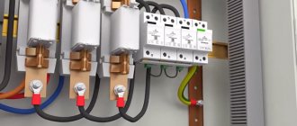
On the back of the device between the two terminals, look for an image in the form of a snake (pins L1 and N1).
This is where the cable for a warm floor or electric mat is connected.
To the end of L1 is the central core of the cable, to N1 is the braid.
An external temperature sensor that prevents overheating of heated floors and controls heating is mounted on blocks with a sensor image (NTC).
The polarity of connecting the sensor wires is not important. Connect them in any order.
Temperature determination error
Please note that the temperature directly at the remote sensor will always be higher than the temperature in the room, which the regulator shows on its display.
This is due to the depth of the sensor in the screed.
Usually this delta, between t on the floor surface and t inside the screed, does not exceed 5-7 degrees.
On the displays of electronic devices you can see both parameters, but in mechanical devices with a wheel, degrees are often not even written around the circumference, but only the numbers 1-2-3, etc. are indicated.
With five digits, one division corresponds to approximately 8 degrees.
Degrees are not indicated for a specific purpose, so as not to confuse the user. You set the thermostat housing to +25C, but the room thermometer in the apartment will only show +20C.
Most people will immediately ask the question: why does the regulator operate with such an error? Is it broken?
No, he's fine. In this case, the sensor in the floor warms up to +25C, not the air in the room. That is why manufacturers simply indicate numbers in mechanics, so that you, focusing only on your feelings, can choose the most comfortable mode for yourself.
If degrees are indicated on your mechanical thermostat, this means that it mainly works and is guided by its own air temperature sensor built into the housing.
The one that is connected to it from the outside and hidden in the tie only plays the role of protecting the cable from overheating.
Supply 220V power to terminals L and N through an RCD with a leakage current of no more than 30mA.
The diagram for connecting a heated floor directly through a thermostat from different manufacturers is the same and looks like this.
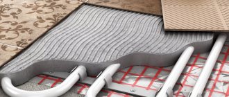
Description of the heating system
The most widespread today are warm electric floors, which can be installed with equal success in apartments in high-rise buildings or in private buildings. The use of modern technologies has made it possible not only to increase the efficiency of home heating, but also to significantly reduce utility bills.
The operating principle of such equipment is based on the property of semiconductors to emit heat when electricity passes through them. Accordingly, by decreasing or increasing the current intensity, you can effectively heat the room.
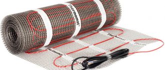
In the past, the most popular heating cables were those that ran under the floor and emitted heat as they passed through an electrical wire. Today, special infrared mats are considered advanced technology, which significantly reduce energy consumption, have high efficiency and are easy to install.
When connecting a heated floor yourself, you need to be careful, any mistake can lead to failures
Connection diagram for high power heated floors
When connecting, be sure to check the power that the thermostat can pass through. Usually it is designed for a load of no more than 16A (3.7 kW at a voltage of 230V).
This is exactly the maximum value. It is recommended to use the device under a constant load of no more than 70% of this power.
In this case, the device will last a long time and function properly. The switch that switches the contact quickly fails when overheated. And along with it you will have to change the entire device.
For loads greater than 3.7 kW, a modular contactor will be required.
The connection diagram in this case will change to the following.
Here, instead of the load, the wires from the regulator go to the contacts of the switching coil (A1-A2), and the heating cable itself is connected to the power terminals of the starter (1-2 or 3-4).
Phasing on the thermostat
A common question is: is there a difference where to connect the phase on the thermostat and where to connect the zero?
Yes, I have. This does not affect the operating logic of the device, but it does not affect the safety.
If you confuse the phase and zero, then when the thermostat is turned off, it will not be the phase conductor that will break, but the neutral one. Thus, the phase will be constantly present on the underfloor heating cable, which is naturally not safe.
In those devices that have a separate switch on the case, when it is pressed, two conductors are broken at once, both phase and zero. But this is in manual shutdown mode, and not in all models.
Often the zero is fed directly through its track. I went into the terminal and immediately went to the heated floor.
In this case, the switch itself is only responsible for interrupting the power supply to the control board. When automatically triggered by a sensor, only one wire is always broken.
What does a thermostat do?
Devices of the type in question belong to the class of thermostats. For example, this is considered a thermostat with a remote temperature sensor. This means that the relay maintains the temperature within the specified limits. When the temperature goes beyond these limits, the relay switches the heating device: boiler, heated floor, heater or heating element. The switching is done in such a way that the temperature returns to the set limits.
In the simplest case, the thermostat turns on the heater when the temperature drops and becomes less than the required one, and turns it off when the temperature rises above the required one. Complex thermostats can connect and disconnect several sections of heaters or smoothly regulate power.
Thermal relay in a heated floor system
Thermal relays consist of two required parts: a temperature sensor and an actuator - this is the part that closes the contacts in the power circuit. These parts are combined into one device or connected using a cable. In each of these cases, the relay operates correctly only when the sensor is located where the set temperature is maintained.
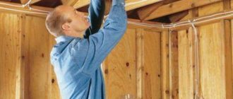
Example of installing a remote sensor
In addition to the sensor and output contacts, thermal relays often also contain a device for setting the desired temperature. In older devices, such a device looked like a rotary knob or dial with a scale marked along the radius of the indicating beak or mark. New, modern devices are mostly digital and contain several keys and a display. But in some models, the temperature is still set with a rotary knob, which is preferred by consumers, mainly older people with established habits. There is enough choice on the market.
Do you need land?
Also note that the protective grounding is directly to the thermostat itself at class=”aligncenter” width=”700″ height=”434″[/img]
This can be a separate, separate terminal through which the heating cable shield is connected to the protective conductor.
The thermostats themselves even have a “square within a square” icon, which means a device with double insulation.
These marks are typically found on portable tools that do not require a grounding pin on the power cord plug.
The difference between expensive electronic thermostats and mechanical ones
What super-tasks are solved by smart thermostats filled with electronics and a display? It would seem, why buy an expensive product if you can buy a regulator with a mechanical wheel and set the desired temperature for yourself in the same way?
And the point here is one of the fundamental problems of comfortable operation of heating systems - inertia.
The fact is that having set an acceptable temperature on warm floors in the region of 23-25C, after reaching it, even with the heating device turned off, the system will still continue to gain degrees by inertia up to a certain point.
The same applies to the minimum parameter. In fact, such fluctuations in a room can reach from 19 to 27C.
There is no question of maintaining comfortable conditions with such variations. In smart electronic thermostats, all this is solved by PWM regulation.
This term comes from radio electronics. There PWM is pulse width modulation. In heating, this principle consists of changing the switching time and operation of the heating elements.
While the temperature in the room is far from the desired parameters (set at +25C, in the room +18C), the heated floors are turned on all the time (heating, heating and heating).
However, as the set point is reached (+25C), heat begins to be supplied as if in small, short pulses (on-off). Due to this, the temperature is accurately maintained in a comfortable area.
In this case, you can forget about inertial processes associated with overheating or, conversely, excessive cooling. You won't get anything like this from a thermostat with a wheel.
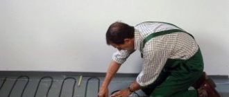
Possible installation errors
For the proper functioning of the film heating system, perfect accuracy of installation and connection of the entire device is required. In the process of performing independent installation work, mistakes are often made. Therefore, you should know what not to do when installing such equipment:
- lay the film overlapping;
- install one thermostat on two separate circuits;
- attach the film to the base using nails or other sharp fasteners;
- install equipment near other heating devices;
- connect the device without isolating the contacts to the electrical network;
- use a material containing foil as a substrate;
- cover the system with cement mortar;
- install large pieces of furniture in places where the film passes;
- bend the material with the carbon mixture at a right angle.
To avoid damage to the film during renovation work indoors, it is recommended to maintain precise laying diagrams.
Compared to many other floor heating systems, installation of film heating equipment is much simpler. Following the diagrams and instructions provided by the manufacturer, you can install the device yourself. But connecting the system to the network requires certain professional skills. Therefore, the process of connecting all devices must be carried out by a qualified electrician.
Thermostat is not working - how to check?
At the same time, do not expect any major changes when replacing a thermostat from one model to another. There is an opinion that if the warm floor does not heat up, then it is worth changing the thermostat to a more expensive one, everything will change by itself.
The air temperature in the room will immediately rise, and where it was previously cold, it will become hot. Roughly speaking, the thermostat is like the speedometer in your car.
You can draw 300-350 km/h on the speedometer, but if the engine is not capable of producing such power, then you will not see this speed. If something is to blame for the poor performance of heated floors, then first of all look at the temperature sensor.
Checking the functionality of the thermostat is very simple. Supply it with 220V power and connect the remote sensor.
Next, instead of a warm floor, connect a regular incandescent light bulb to the thermostat. You begin to unscrew the knob, changing the temperature.
At a certain moment the light should light up.
Next, hold the temperature sensor in your hand and wait. When heat comes from your body, a working thermostat will turn on and the light bulb will go out.
If the sensor is hidden deep in the screed, you can warm up the area with a hairdryer and wait for the same effect. When the lamp does not react at all, this indicates a malfunction of the device.
The fastest way to repair in this case is to transfer the work from the floor sensor to the air sensor built into the housing.
The ends of the cable on the device from the floor temperature source will have to be unscrewed, and the settings of the device itself will have to be reset.
All this will work correctly provided that the thermostat is installed directly in the heated room.
If you have an electronic thermostat with PWM control, then using the above test method, it is not recommended to heat the sensor too quickly with an extraneous heat source. What does this mean?
Firstly, the thermostat will immediately detect an abnormal increase in heat and work ahead of time. Secondly, the “smart brains” of the device will forcibly turn off the heating for the next 20 minutes.
In this case, after just 5 minutes the temperature on the device’s display will be sufficient to turn on, and startup and contact closure will not occur. As a result, you will have doubts about the correct operation of the thermostat.
Therefore, the fast heat test is ideal for mechanical devices, but be careful with electronic ones.
Manual adjustment of TP collectors
The simplest, although time-consuming, setting method is to adjust the temperature of the heated floor using manual valves. The task is somewhat simplified by installing flow meters (rotameters) on the comb.
Flow meters simplify the dosage of the amount of circulating coolant (flow) in one separate circuit of the underfloor heating system. In the case of group temperature control throughout the collector, the rotameter can also be used to balance the flow of coolant (smoothing out the difference in hydraulic resistance) along loops of different lengths.
The main elements of a flow meter valve are:
- housing with shut-off and control valve. It is screwed into the corresponding technical hole of the manifold;
- a flask made of transparent plastic or glass with a printed scale;
- float indicator that allows you to visually control the flow of liquid through the rotameter.
Manual adjustment of the underfloor heating manifold is carried out by screwing/unscrewing manual valves or adjusting the throughput of flow meters.
The sequence of manually setting the temperature of a warm water floor
At the beginning of the adjustment operations, it is necessary to make sure that the pipelines of the TP system (secondary circuit) are completely filled with coolant and have no air pockets. They are filled following the main heating system (primary circuit). At this time, all shut-off and control valves on the collectors must be closed.
After opening the main valves for the supply and return of the distributors for heated floors, the shut-off devices on each of the loops are opened sequentially. Air is bled through Mayevsky valves or automatic comb air vents. It is recommended to fill the next branch only after the previous one has been completely filled and its air has been guaranteed.
Having completed filling the first loop, it is necessary to turn on the heat pump of the secondary heating circuit and circulate the coolant through its system. The efficiency of liquid circulation is checked with built-in or overhead thermometers. As a last resort, you can simply put your hands on the supply and return pipes at the same time - they should be warm, but with a slight difference in heating.
The filled first loop should be cut off from the collectors at both ends using local shut-off and control valves. Then, the above actions are carried out with the next loop.
After sequential filling of all heat pump circuits, their shut-off devices are opened and the heat pump is switched on to operating mode. The temperature of the warm water floor is adjusted through the supply of coolant to each of its branches. It is set by changing the liquid flow rate (with a valve or rotameter), and control is carried out by changing the temperature gradient between the supply and return flow. Ultimately, this difference for different circuits should be the same, within 5-15C. The longer the loop, the more intense the coolant will cool and the greater its consumption required.
To monitor the correct adjustment of a warm water floor, it is rational to use non-contact laser or contact electric thermometers. Their installation to measure the temperature of the supply and return pipes will help reduce the time to obtain the result of changing settings from several hours to 10-15 minutes.
Connecting a temperature sensor
Another error occurs when replacing or connecting sensors from different manufacturers to the same regulator. The fact is that they all have a certain resistance corresponding to a particular temperature.
And if you change the temperature sensor to another without changing the settings, this may lead to incorrect heating operation. The difference in temperature between the detected and actual temperature can reach 10 degrees!
Due to a different resistance, less than the factory one, the regulator will understand this as an excessive temperature and give a command to turn off early, although the heated floors will not yet be warm enough.
For heated floors, so-called NTC sensors are used - negative temperature coefficient sensors. This term means that as the ambient temperature increases, their resistance decreases.
There is also PTC - positive t coefficient. resistance. The reverse process occurs with them.
Advanced devices (Devireg Touch) initially have several types of sensors included in the settings program. At the installation stage, simply select the required one.
If you don't know the brand, you will have to manually measure the resistance with a multimeter.
The received data is compared and checked whether they correspond to the factory settings or not.
The most correct heating system is considered to be one that has its own control zone in each room. What does this mean?
If there is only one thermostat in the house, the temperature spread in different parts of the building will reach 5-6 degrees.
Therefore, you will have to buy and install not one, but several thermostats.
You can set separate controllers for two zones simultaneously, while changing the temperature priority. That is, install it in a thermostat in one room, and run a remote sensor from it into the next room.
In this case, in the settings you will need to select which element the thermostat should respond to - one built into the housing or an external one. You will not be able to achieve the same temperature from one device.
It is prohibited to place thermostats in wet areas. They must have an appropriate IP level of moisture protection and be installed in zone 3.
What kind of zone this is, read in a separate article.
Types, design and principle of operation of infrared film floors
Most of the film materials used on the Russian market for organizing heated floors are of South Korean or domestic origin. This is due to several factors:
- uniform heating of the material over almost the entire area;
- convenient standard sizes: mainly roll deliveries 100 m long of various widths (500–1000 mm) with a cutting pitch of 200–250 mm;
- several types of power ranging from 110–400 W/sq.m;
- record quality guarantees (10–20 years of operation);
- optimal price accessible to most consumers.
The most famous manufacturers of infrared film materials are Q-Term , Heat Plus , RexVA , STEM Energy , Hit-Lite and several other companies. These are carbon-based electric heaters, supplied in coils, the operating features of which we will analyze.
Installation of a film heated floor includes laying a special film across which carbon heaters are located (see figure) having a linear shape.
These heaters have a strictly calculated resistivity. When an electric current passes here, electrical energy is converted into thermal energy, that is, the film heats up. The resulting heat is evenly distributed over the entire surface, quickly warming up the coating of your finished floor.
Current-carrying copper strips (busbars) are located on both edges of the roll. A variety of standard sizes and marking of cutting lines allows you to cut the film material directly on site with virtually no losses. In addition, thanks to its great flexibility, elasticity and minimal thickness (only 0.338 mm ), the material adheres perfectly to any surface, without requiring special preparation when installing a heated film floor. The weight of one “square” electric heater is 0.4 kg .
The main types of power of South Korean films: 150, 220, 300, 400 W/sq.m (less common options are also available). The width of the material most often has the following steps: 0.5, 0.8 and 1.0 m . All South Korean heaters have proven themselves to be excellent. The main thing is an accurate connection diagram for the film heated floor, high-quality installation in accordance with the instructions provided and proper operation. Many of these heaters are suitable not only for equipping heated floors, but also for heated ceilings (including as the main heat sources).
Among Russian manufacturers of infrared electric heaters, ZEBRA EVO-300 WF occupies a special place. This is an excellent development, which gained fame after the release of popular heaters for heated ceilings (ZEBRA EVO-300 series SOFT, ST, PRO, EX). EVO-300 WF was created specifically for heated floors. "Zebra" is a modular device, equipped with a grounding loop and a housing made of aluminum foil .
The main advantage of the Zebra WF is one-way thermal radiation , in which up to 95% of the energy goes directly to heating, providing record system efficiency.
An approximate connection diagram for the ZEBRA EVO-300 WF film heated floor is presented below. .