Thyristor converters make it possible to supply electric current pulses of various configurations to the motor. Features and throughput vary depending on system specifications and the device itself.
Recently, industrial systems driven by electricity increasingly include a thyristor converter for the DC motor. These semiconductor valves allow the drive to be controlled over a significant range: the current can exceed hundreds of amperes, and the voltage reaches 1000V and higher.
Despite its increased technical performance, the thyristor electric drive is distinguished by its compact overall dimensions. At the same time, its performance exceeds that of other systems for similar purposes, and the operating temperature range allows the DC motor to be operated in an environment from -60 to +60 Celsius.
What is a thyristor
A thyristor system is a partially controlled voltage conversion system. The general operating scheme involves activation of the drive at the moment the potential of the required level is applied to the control electrode. To turn off the thyristor DC motor converter, it is necessary to perform a forced circuit break. This can be done in three ways:
- apply a quenching voltage having a value opposite to the starting pulse;
- turn off the power supply to the entire drive;
- pass the supply current through zero.
The rotation speed of the electric motor depends on the average voltage value that has already passed through the rectifier. A thyristor electric drive allows you to control the moment at which the main flow of rectified voltage is supplied and its delay. By adjusting the feed torque, the overall control of a DC motor can be achieved.
System thyristor converter - motor (TP - D)
In the TP-D system, an independently excited DC motor is powered by a thyristor-side converter. The schematic diagram of the system is shown in Fig.
Average value of the rectified voltage of the TP.
, Where
U2 is the effective value of the phase voltage of the secondary winding of the supply transformer (or network in transformerless circuits).
m – number of ripples of rectified voltage;
a is the opening delay angle of the thyristors;
Ud0 – maximum value of the average rectified voltage at a=0.
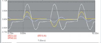
The rectified voltage curves, taking into account the phenomenon of valve commutation, characterized by angles g, are shown in Fig.
The dependence of the EMF of the TP on the control voltage Uу with a linear characteristic of the SIFU is presented in the following figure. When it is replaced by a linearized TP as a dynamic link of the electric drive system in continuous current mode, it is described by the equation , where is the voltage gain of the TP; — small time constant of the TP, taking into account discreteness, delay and the presence of filters in the SIFU.
Equation of electrical equilibrium in the armature circuit of the TP-D system
, Where
Here Rя is the resistance of the motor armature circuit;
is the inductive reactance of the transformer phase due to leakage fields, and x2 and x1 are the inductive leakage reactances of the secondary and primary windings of the transformer;
Rdr – resistance of the smoothing choke;
Rtr – active resistance of the transformer phase windings, reduced to the secondary circuit;
Rav.v – average resistance of valves
Keeping in mind that ; ; , we obtain the equation of the mechanical characteristics of the engine for any operating mode
or
Because , where , then
It follows that in the continuous current mode, the mechanical characteristics of the motor in the TP-D system, under the accepted assumptions, are similar to the characteristics of the GD system.
For , we obtain the equation of static characteristics
or
The equations for the static mechanical and electromechanical characteristics of the motor for the continuous current mode can be presented in the following form:
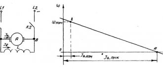
The family of static mechanical characteristics for various a is shown in Fig. These are straight segments cutting off the ordinate axis, corresponding to the ideal idle speed
However, in reality, when separately controlling sets of valves (in the case of two complete converters) or when powered from a single-set transformer in the area of small loads, the current becomes intermittent, and at Uy = 0 and the average value of Ud becomes . A zone of intermittent currents appears; the larger the angle a, the larger it is.
The appearance of a zone of intermittent currents is due to the fact that at certain periods of time the instantaneous value of the rectified voltage of the converter becomes less than the counter-acting EMF of the motor, as can be seen from the graph of the rectified voltage, and, as follows from the EMF equilibrium equation, the difference Ud-e becomes negative. The current must change direction to the opposite. But since the valves have one-way conductivity, the current becomes zero. The valves close, the current appears again when Ud becomes greater than e. At high loads, despite the fact that at certain periods of time the instantaneous value of Ud becomes less than the EMF of the motor, the current is not interrupted and is continuous. This is explained by the fact that at heavy loads the supply of electromagnetic energy in the rectified current circuit is significant. The self-induction emf that appears when the current disappears is added to the instantaneous rectified voltage of the TP and in total they exceed the motor emf. Therefore, the difference between this sum and the EMF of the motor is positive and the current is not interrupted. At low loads, the self-induction EMF turns out to be insufficient to maintain the current and it is interrupted.
The transition from the continuous to intermittent current mode corresponds to the initial continuous current mode, which is the boundary between the two indicated. The magnitude of the boundary current depends on the angle a and circuit parameters, where
Boundary currents (moments) lie on the arc of an ellipse, shifted along the ordinate axis by an amount (see figure with mechanical characteristics).
Note that if the engine is powered by an irreversible TP, then the electric drive system becomes incompletely controllable, because the current can only flow in one direction. Accordingly, mechanical characteristics in the second and third quadrants do not exist.
In the presence of a zone of intermittent currents, the electromechanical and mechanical characteristics in this zone are not expressed analytically. They resemble the mechanical characteristics of a series motor, as shown in Fig. As the load decreases, the motor speed increases and its counter-emf increases, which causes the load current of the converter to decrease. This leads to a decrease in the voltage drop across the internal resistances of the circuit, as well as to a decrease in the average voltage losses caused by the switching phenomenon. In this regard, Ud increases. With an ideal idle speed of the engine, the voltage drops across the valves and internal resistances of the circuit disappear and Ud increases even more. The voltage on the motor (during the current pulse) approaches the amplitude of the AC voltage supplying the converter and the motor speed increases. Therefore, in the zone of low and zero loads, the mechanical characteristics of the engine are soft, as shown in the graph. The ideal engine idle speed for these characteristics can be determined from the expressions:
at and
at
Here E2f.m is the amplitude of the phase EMF of the secondary winding of the supply transformer or the amplitude of the phase voltage of the supply network (in transformerless circuits).
DUV – voltage drop in valves.
Using the equation of dynamics of the TP, the equation of equilibrium of the EMF in the armature circuit, the equation of the mechanical characteristics of the motor in the TP-D system and the equation of motion of the electric drive with rigid mechanical connections, it is possible to depict a block diagram of the TP-D system, which has the form.
When representing the equation in the form
, Where
The block diagram will look like this.
The engine in the TP-D system can operate in all modes.
The motor mode corresponds to the area in squares 1 and 3; the dynamic braking mode corresponds to the characteristic passing through the origin of coordinates at . The counter-switching mode corresponds to the area enclosed between the torque axis and the dynamic braking characteristic. The recuperation mode corresponds to the area between the ordinate axis in squares 2 and 4 and the dynamic braking characteristic. Braking and reversing the engine in the TP-D system and static mechanical characteristics of a reversible valve electric drive.
Reversing the engine consists of braking to a stop and accelerating in the opposite direction. In the TP-D system it can be done:
a) changing the polarity of the motor power supply using reversing contactors or reversing thyristors according to the following scheme. This method is advisable if the reverse time is not significant. Reverse duration is at least 0.1 sec.
b) changing the direction of the magnetic flux of the motor while maintaining the same direction of the armature current, which is possible using reversing contactors in the excitation circuit, as shown in the following diagram. However, the duration of the reverse in this case is on the order of 0.5-2.5 s.
c) For electric drives, where maximum speed during reverse is required, as well as the need for both motor and braking modes in one direction of rotation, transformer transformers with two sets of valves are used, each of which serves to power the motor in one direction of rotation, thereby creating a two-way effect conductivity of the converter.
As mentioned above, reverse consists of braking the engine and accelerating it in the opposite direction. The main method of braking in the TP-D system is braking with energy recovery into the network. Unlike a diesel engine system, this mode cannot be obtained only by increasing the speed above the ideal idle speed. Although at w>w0 the EMF of the motor will become greater than Ud, the current in the armature circuit will be interrupted, because The EMF of the motor will be applied to the valves of the converter in the direction opposite to their conductivity, and the valves will close. To recover energy into the network, it is necessary to convert direct current energy, the source of which at w>w0 is the engine, into alternating current energy. To do this, the TP must be switched to inverter mode. In practice, to enable braking of an electric drive with energy recovery, two sets of valves are used in the network, connected in a bridge circuit, as shown in Fig. and combine their control device into one control element.
In the rectifying mode of the converter, the active component Ia1 of the first harmonic of the phase current coincides in direction with the voltage (EMF) of the phase, and the reactive component Ip1 lags behind by 90°. Consequently, the converter consumes active and reactive power from the network. If j1 becomes greater than 90°, which at g=0 corresponds to a>90°, then Ip1 will still lag behind Eph by 90°, and Ia1 will be directed counter to the phase EMF. In this case, the converter will supply active power to the network while simultaneously consuming reactive power. This mode is inverter. In it, the current source is the EMF of a direct current machine, which exceeds the voltage of the converter.
That. to obtain the inverter mode of operation of the transformer, it is necessary that a be greater than 90°, i.e. it is necessary to force the converter by increasing angle a to forcibly rectify the negative half-waves of the supply voltage. He himself will not do this, so inverter mode can only take place with forced commutation. In this case, the sign of voltage Ud will change.
It is known that in a direct current circuit, a change in the direction of energy transfer is usually associated with a reversal of the current. But the same effect also occurs when the sign of the voltage changes, as can be seen from the relation p=ui.
Because valves have one-way conductivity, then to change the direction of power flow with a constant direction of current, you need to change the sign of the voltage, i.e. it is necessary to force the converter to forcibly rectify the negative half-waves of the supply voltage, which is done to implement regenerative braking of the engine.
The transition of the converter from rectifier to inverter mode can be illustrated using timing diagrams (without taking into account the commutation angle g).
When switching to inverter mode, the AC and DC voltages switch roles so that the valves do not notice this. The polarity of the voltage at the converter terminals and the direction of the current through the valves remain unchanged. The rectifier, switching to inverter mode, continues to rectify the AC voltage, but only its negative half-waves. The control angle in this mode is measured to the left from the point of intersection of the supply network voltage sinusoids in the negative region and is called, as is known, the advance angle b. It is equal to b=pa. Instead of the commutation angle g for the inverter mode, it is customary to use the concept of the locking angle d=bg or, in other words, the safety angle
In the inverter mode of the transformer, the same voltage drops occur as in the rectifier mode of the converter. However, they are covered not by the network, but by the DC source, i.e. engine. Therefore, replacing a with b in the expressions of the electromechanical and mechanical characteristics and taking into account that the current in the armature circuit in the inverter mode of the converter, therefore, the braking mode of the motor, is determined by the difference between the EMF of the motor and Ud of the converter, acting counter to the EMF of the motor and has the opposite direction compared to current in motor mode, the equations for the electromechanical and mechanical characteristics of the engine in regenerative braking mode take the form:
The family of mechanical characteristics corresponding to different angles b when the engine is powered from a single-set TC is presented in the following figure. At low loads, just as in motor mode, current interruptions and a sharp change in speed occur.
In the case of powering the engine from a two-set TP with their joint control and linear coordination, the electromechanical and mechanical characteristics of the reversible valve electric drive are similar to the characteristics of the gas engine system, as shown in the following figure. When sets of valves are jointly controlled, but not fully coordinated, the linearity of the characteristics is violated and they look as shown in the following figure.
The electromechanical and mechanical characteristics of a reversible valve electric drive with separate control of sets of valves significantly depend on the method of matching control angles. With linear matching, in particular, they have the form shown in the following figure.
To implement regenerative braking of an electric drive with two sets of valves, it is necessary to close the valves of the converter operating in rectifier mode, for which it is enough to set the angle and under the influence of the motor EMF the valves will close, and the current in the armature circuit will become equal to 0. After this (if the control is not joint) it is necessary apply unlocking pulses with an advance angle b=bmin to the valves of the second converter, which ensures inverter mode, in which a current will appear in the armature circuit due to the difference between E and Udu, coinciding in direction with E of the motor. The sign of the electromagnetic torque will change to the opposite and the drive will operate in braking mode with energy recuperation into the network. By increasing b to 90° (see characteristics below the torque axis), you can reduce the speed almost to a complete stop of the drive.
With one set of valves and reversing using contactors, to switch to the regenerative braking mode, the converter valves are closed, setting the angle . Then, by means of reversing contactors, the armature circuit of the motor is switched so that its EMF acts in the direction of direct conduction of the valves, and unlocking pulses are supplied to them, ensuring the inverter mode of the converter and the braking mode of the engine.
In the TP-D system, an independently excited DC motor is powered by a thyristor-side converter. The schematic diagram of the system is shown in Fig.
Average value of the rectified voltage of the TP.
, Where
U2 is the effective value of the phase voltage of the secondary winding of the supply transformer (or network in transformerless circuits).
m – number of ripples of rectified voltage;
a is the opening delay angle of the thyristors;
Ud0 – maximum value of the average rectified voltage at a=0.
The rectified voltage curves, taking into account the phenomenon of valve commutation, characterized by angles g, are shown in Fig.
The dependence of the EMF of the TP on the control voltage Uу with a linear characteristic of the SIFU is presented in the following figure. When it is replaced by a linearized TP as a dynamic link of the electric drive system in continuous current mode, it is described by the equation , where is the voltage gain of the TP; — small time constant of the TP, taking into account discreteness, delay and the presence of filters in the SIFU.
Equation of electrical equilibrium in the armature circuit of the TP-D system
, Where
Here Rя is the resistance of the motor armature circuit;
is the inductive reactance of the transformer phase due to leakage fields, and x2 and x1 are the inductive leakage reactances of the secondary and primary windings of the transformer;
Rdr – resistance of the smoothing choke;
Rtr – active resistance of the transformer phase windings, reduced to the secondary circuit;
Rav.v – average resistance of valves
Keeping in mind that ; ; , we obtain the equation of the mechanical characteristics of the engine for any operating mode
or
Because , where , then
It follows that in the continuous current mode, the mechanical characteristics of the motor in the TP-D system, under the accepted assumptions, are similar to the characteristics of the GD system.
For , we obtain the equation of static characteristics
or
The equations for the static mechanical and electromechanical characteristics of the motor for the continuous current mode can be presented in the following form:
The family of static mechanical characteristics for various a is shown in Fig. These are straight segments cutting off the ordinate axis, corresponding to the ideal idle speed
However, in reality, when separately controlling sets of valves (in the case of two complete converters) or when powered from a single-set transformer in the area of small loads, the current becomes intermittent, and at Uy = 0 and the average value of Ud becomes . A zone of intermittent currents appears; the larger the angle a, the larger it is.
The appearance of a zone of intermittent currents is due to the fact that at certain periods of time the instantaneous value of the rectified voltage of the converter becomes less than the counter-acting EMF of the motor, as can be seen from the graph of the rectified voltage, and, as follows from the EMF equilibrium equation, the difference Ud-e becomes negative. The current must change direction to the opposite. But since the valves have one-way conductivity, the current becomes zero. The valves close, the current appears again when Ud becomes greater than e. At high loads, despite the fact that at certain periods of time the instantaneous value of Ud becomes less than the EMF of the motor, the current is not interrupted and is continuous. This is explained by the fact that at heavy loads the supply of electromagnetic energy in the rectified current circuit is significant. The self-induction emf that appears when the current disappears is added to the instantaneous rectified voltage of the TP and in total they exceed the motor emf. Therefore, the difference between this sum and the EMF of the motor is positive and the current is not interrupted. At low loads, the self-induction EMF turns out to be insufficient to maintain the current and it is interrupted.
The transition from the continuous to intermittent current mode corresponds to the initial continuous current mode, which is the boundary between the two indicated. The magnitude of the boundary current depends on the angle a and circuit parameters, where
Boundary currents (moments) lie on the arc of an ellipse, shifted along the ordinate axis by an amount (see figure with mechanical characteristics).
Note that if the engine is powered by an irreversible TP, then the electric drive system becomes incompletely controllable, because the current can only flow in one direction. Accordingly, mechanical characteristics in the second and third quadrants do not exist.
In the presence of a zone of intermittent currents, the electromechanical and mechanical characteristics in this zone are not expressed analytically. They resemble the mechanical characteristics of a series motor, as shown in Fig. As the load decreases, the motor speed increases and its counter-emf increases, which causes the load current of the converter to decrease. This leads to a decrease in the voltage drop across the internal resistances of the circuit, as well as to a decrease in the average voltage losses caused by the switching phenomenon. In this regard, Ud increases. With an ideal idle speed of the engine, the voltage drops across the valves and internal resistances of the circuit disappear and Ud increases even more. The voltage on the motor (during the current pulse) approaches the amplitude of the AC voltage supplying the converter and the motor speed increases. Therefore, in the zone of low and zero loads, the mechanical characteristics of the engine are soft, as shown in the graph. The ideal engine idle speed for these characteristics can be determined from the expressions:
at and
at
Here E2f.m is the amplitude of the phase EMF of the secondary winding of the supply transformer or the amplitude of the phase voltage of the supply network (in transformerless circuits).
DUV – voltage drop in valves.
Using the equation of dynamics of the TP, the equation of equilibrium of the EMF in the armature circuit, the equation of the mechanical characteristics of the motor in the TP-D system and the equation of motion of the electric drive with rigid mechanical connections, it is possible to depict a block diagram of the TP-D system, which has the form.
When representing the equation in the form
, Where
The block diagram will look like this.
The engine in the TP-D system can operate in all modes.
The motor mode corresponds to the area in squares 1 and 3; the dynamic braking mode corresponds to the characteristic passing through the origin of coordinates at . The counter-switching mode corresponds to the area enclosed between the torque axis and the dynamic braking characteristic. The recuperation mode corresponds to the area between the ordinate axis in squares 2 and 4 and the dynamic braking characteristic. Braking and reversing the engine in the TP-D system and static mechanical characteristics of a reversible valve electric drive.
Reversing the engine consists of braking to a stop and accelerating in the opposite direction. In the TP-D system it can be done:
a) changing the polarity of the motor power supply using reversing contactors or reversing thyristors according to the following scheme. This method is advisable if the reverse time is not significant. Reverse duration is at least 0.1 sec.
b) changing the direction of the magnetic flux of the motor while maintaining the same direction of the armature current, which is possible using reversing contactors in the excitation circuit, as shown in the following diagram. However, the duration of the reverse in this case is on the order of 0.5-2.5 s.
c) For electric drives, where maximum speed during reverse is required, as well as the need for both motor and braking modes in one direction of rotation, transformer transformers with two sets of valves are used, each of which serves to power the motor in one direction of rotation, thereby creating a two-way effect conductivity of the converter.
As mentioned above, reverse consists of braking the engine and accelerating it in the opposite direction. The main method of braking in the TP-D system is braking with energy recovery into the network. Unlike a diesel engine system, this mode cannot be obtained only by increasing the speed above the ideal idle speed. Although at w>w0 the EMF of the motor will become greater than Ud, the current in the armature circuit will be interrupted, because The EMF of the motor will be applied to the valves of the converter in the direction opposite to their conductivity, and the valves will close. To recover energy into the network, it is necessary to convert direct current energy, the source of which at w>w0 is the engine, into alternating current energy. To do this, the TP must be switched to inverter mode. In practice, to enable braking of an electric drive with energy recovery, two sets of valves are used in the network, connected in a bridge circuit, as shown in Fig. and combine their control device into one control element.
In the rectifying mode of the converter, the active component Ia1 of the first harmonic of the phase current coincides in direction with the voltage (EMF) of the phase, and the reactive component Ip1 lags behind by 90°. Consequently, the converter consumes active and reactive power from the network. If j1 becomes greater than 90°, which at g=0 corresponds to a>90°, then Ip1 will still lag behind Eph by 90°, and Ia1 will be directed counter to the phase EMF. In this case, the converter will supply active power to the network while simultaneously consuming reactive power. This mode is inverter. In it, the current source is the EMF of a direct current machine, which exceeds the voltage of the converter.
That. to obtain the inverter mode of operation of the transformer, it is necessary that a be greater than 90°, i.e. it is necessary to force the converter by increasing angle a to forcibly rectify the negative half-waves of the supply voltage. He himself will not do this, so inverter mode can only take place with forced commutation. In this case, the sign of voltage Ud will change.
It is known that in a direct current circuit, a change in the direction of energy transfer is usually associated with a reversal of the current. But the same effect also occurs when the sign of the voltage changes, as can be seen from the relation p=ui.
Because valves have one-way conductivity, then to change the direction of power flow with a constant direction of current, you need to change the sign of the voltage, i.e. it is necessary to force the converter to forcibly rectify the negative half-waves of the supply voltage, which is done to implement regenerative braking of the engine.
The transition of the converter from rectifier to inverter mode can be illustrated using timing diagrams (without taking into account the commutation angle g).
When switching to inverter mode, the AC and DC voltages switch roles so that the valves do not notice this. The polarity of the voltage at the converter terminals and the direction of the current through the valves remain unchanged. The rectifier, switching to inverter mode, continues to rectify the AC voltage, but only its negative half-waves. The control angle in this mode is measured to the left from the point of intersection of the supply network voltage sinusoids in the negative region and is called, as is known, the advance angle b. It is equal to b=pa. Instead of the commutation angle g for the inverter mode, it is customary to use the concept of the locking angle d=bg or, in other words, the safety angle
In the inverter mode of the transformer, the same voltage drops occur as in the rectifier mode of the converter. However, they are covered not by the network, but by the DC source, i.e. engine. Therefore, replacing a with b in the expressions of the electromechanical and mechanical characteristics and taking into account that the current in the armature circuit in the inverter mode of the converter, therefore, the braking mode of the motor, is determined by the difference between the EMF of the motor and Ud of the converter, acting counter to the EMF of the motor and has the opposite direction compared to current in motor mode, the equations for the electromechanical and mechanical characteristics of the engine in regenerative braking mode take the form:
The family of mechanical characteristics corresponding to different angles b when the engine is powered from a single-set TC is presented in the following figure. At low loads, just as in motor mode, current interruptions and a sharp change in speed occur.
In the case of powering the engine from a two-set TP with their joint control and linear coordination, the electromechanical and mechanical characteristics of the reversible valve electric drive are similar to the characteristics of the gas engine system, as shown in the following figure. When sets of valves are jointly controlled, but not fully coordinated, the linearity of the characteristics is violated and they look as shown in the following figure.
The electromechanical and mechanical characteristics of a reversible valve electric drive with separate control of sets of valves significantly depend on the method of matching control angles. With linear matching, in particular, they have the form shown in the following figure.
To implement regenerative braking of an electric drive with two sets of valves, it is necessary to close the valves of the converter operating in rectifier mode, for which it is enough to set the angle and under the influence of the motor EMF the valves will close, and the current in the armature circuit will become equal to 0. After this (if the control is not joint) it is necessary apply unlocking pulses with an advance angle b=bmin to the valves of the second converter, which ensures inverter mode, in which a current will appear in the armature circuit due to the difference between E and Udu, coinciding in direction with E of the motor. The sign of the electromagnetic torque will change to the opposite and the drive will operate in braking mode with energy recuperation into the network. By increasing b to 90° (see characteristics below the torque axis), you can reduce the speed almost to a complete stop of the drive.
With one set of valves and reversing using contactors, to switch to the regenerative braking mode, the converter valves are closed, setting the angle . Then, by means of reversing contactors, the armature circuit of the motor is switched so that its EMF acts in the direction of direct conduction of the valves, and unlocking pulses are supplied to them, ensuring the inverter mode of the converter and the braking mode of the engine.
General classification
By conducting a study of a system that assumes the presence of a thyristor, you can determine the most optimal switching circuit. The selected startup type directly determines the average voltage level produced by the rectifier in the absence of operator intervention. In cases where a thyristor is used for a DC motor, two classes of thyristor converters are used - bridge and equipped with a zero-value output.
A bridge-type thyristor converter is usually installed in high-power systems. This is optimal due to the fact that each such thyristor can have a lower voltage level, which makes it possible to distribute the total load between several nodes and reduce the load on each of them. In addition, the voltage rectified through the bridge thyristor will not have a constant component, which increases the stability of operation when electric current passes through the converting windings.
Another difference between different classes of thyristors is the number of phase outputs. Equipment and devices with low power consumption require a thyristor to have only a few phases. If the converter is designed to operate in highly loaded systems, its design may include from 12 to 24 phase contacts.
Regardless of the chosen activation type and overall design, this category of voltage converters will have all the advantages of using thyristors. This includes the complete absence of rotating parts, which accelerate the wear process and require periodic replacement. This leads to another advantage – low inertia. The main difference from simple electromechanical electric current converters is their compactness, which has a positive effect on compatibility with devices where there is little free space.
With all its advantages, the thyristor converter has a number of disadvantages:
- if the voltage is adjusted downward, the output power begins to fall in proportion to the decrease in power supply;
- when the converter operates, higher harmonics are created, which immediately enter the power supply network of the entire system;
- The thyristor is rigidly connected to the power supply circuit, which is why the slightest voltage surge is immediately reflected in the system. Changing the characteristics of the current supplied to the motor creates a push on the axis, abruptly changing the speed of its rotation, and this in turn causes a surge in current.
The performance of an electric motor, which operates in conjunction with a thyristor converter, directly depends on the voltage level supplied to the armature. The load generated by the drive also plays an important role.
Application and features of DC drives with thyristor type converter.
Electric drives with thyristors, due to their high efficiency in operation, have become widespread in various industrial sectors.
The main advantages of this electrical equipment are: - high efficiency rates (up to 98%)
— dynamism and speed
— wide range of production process control
— stability and reliability when working with heavy loads
- relatively small dimensions
An engine equipped with a controlled converter gains the ability to fine-tune and adjust parameters at various stages of its operation. For convenience, modern DC drives are equipped with high-tech electronic interfaces, making them easy and safe to operate.
A new family of thyristor electric drives from SIEMENS (Germany).
The new line of SINAMICS DCM models from the global brand Siemens, which replaced the SIMOREG DC MASTER series, embodies all the best technological developments in the field of AC/DC conversion. First of all, they were developed for the needs of the metallurgical, oil production, woodworking, machine tool industries, and for use in working with handling equipment. The widest choice of powers for motor control, and their communication system features provide opportunities for the implementation of network control.
When creating new thyristor DC drives, the developers tried to preserve as much as possible the architecture and functionality of the previous generation SIMOREG DC Master, thereby ensuring the necessary compatibility with the proposed additional elements and software of the series; replacing old equipment with new one will also not create any additional difficulties.
Distinctive features of this range of DC drives:
— universal application due to a high degree of adaptability and flexibility of integration;
— a unified modular system for the further implementation of additional elements for the installation;
— the variability of input and output currents and voltages has been expanded;
— special functional blocks, the so-called graphical design systems (DCC), have been developed to program the operation of the drive;
— the control board has a separate power supply (24VDC);
— sealing of boards with a compound and power busbars with a nickel-plated coating;
— the ability to connect to a single-phase network has been implemented (only for drives with a current of less than 125 A);
— the power section is completely isolated;
— work in a wide temperature range of the environment;
— a convenient operator panel that makes it easy to start and configure the drive;
— electronic control of the parameters of all settings, both from the operating panel and using a computer (free software).
Main technical characteristics of the SINAMICS DCM family of electric drives:
— a huge selection of operating powers in the range from 6 to 30,000,000 W;
— options for two or four-quadrant control are presented;
— supply voltage range from 400 V to 830 V;
— rated current from 15 to 3000 A, and with parallel operation of several units, the values can be significantly increased;
— two options for control electronics are presented: standard for open and closed loop, as well as an advanced board with additional capabilities for controlling drives and combining them into a network;
— reversible and non-reversible types of rectifiers;
— the cooling system of the installation is air, forced;
— equipped with digital innovative devices for ease of use, there is an LCD panel and special Drive Control Chart software;
- standard or cabinet design.
The website catalog presents various options for thyristor drives to solve any production tasks assigned to you, and our highly qualified specialists are always happy to help in selecting equipment to suit your request.
Having decided to buy this converter, you can be sure of the reliability of the proposed equipment, since the German company Siemens has been an undeniable leader in the production of electric drive equipment for several decades and guarantees the standard quality of its products.
SINAMICS DCM thyristor DC drives are the best solution for the successful implementation of industrial projects, its unparalleled production power of time-tested technologies, combined with modern progressive innovations, takes this series to the highest level of quality and functionality.
Typical design and operating principle
A thyristor is a semiconductor made of silicon. Typically, it consists of four conductive layers. The assembly is carried out on a copper base, which has six sides and a threaded shank. This element is complemented by a main structure, in the production of which special silicon is used.
The four-layer transmission complex has two outputs - control and negative. From the outside, the entire structure is protected by an iron casing shaped like a cylinder and equipped with an insulating layer. Using a thread, the thyristor is installed in a special mounting location and connected to the positive pole of the power circuit with anode voltage.
Work management
The general scheme of operation is the passage of electricity through the thyristor under the action of anode voltage. In this case, the magnitude of the output voltage depends on the control current, which is supplied to the control electrode. If the supply of control current is interrupted, the anode voltage going to the consumer will begin to increase, while maintaining a low value.
As the incoming voltage increases, the amount of current required to turn on the thyristor decreases. There is a direct proportion between these indicators, which can be traced in any design of a thyristor converter.
Using the sine law to control the incoming voltage also allows you to reduce the voltage level. In this case, the control current decreases in proportion to the pulse required to open the main mechanism. Maintaining a constant control voltage does not lead to the opening of the thyristor when its level is lower than that of the control pulse.
Increasing the control voltage causes the thyristor to open under certain conditions. To do this, it is necessary to ensure that the control pulse indicator is exceeded. Using the ability to configure the characteristics of the control pulse, you can change the opening angle of the thyristor in the range from zero to 90 degrees.
In cases where it is necessary to open the thyristor to a larger angle, the control voltage changes to alternating. In most situations, the amplitude of the current is sinusoidal. When the voltage reaches a value equal to the point at which the sinusoid intersects the value of the control pulse, the thyristor opens.
By changing the sine wave interval to a smaller or larger direction, you can also adjust the opening angle of the converter transmission mechanism. This type of thyristor operation control is called horizontal and is implemented through the use of a device called a phase shifter. The opposite type of control - vertical - involves shifting the sinusoid up or down, which also leads to a change in the opening angle of the conductor. To determine the final value required to influence the angle, it is necessary to calculate the sum of the alternating control voltage and the direct current that forms the sine wave. It is possible to set the specific angle at which the thyristor must be opened by adjusting the constant voltage.
Once the thyristor is open to the desired angle, the system maintains the specified position until the positive half-cycle is completed. During this period of time, the control voltage does not affect the functions of the conductor. Thanks to this feature, the use of pulse control becomes possible.
Pulse control consists of applying periodic wave influences equal in magnitude to the control voltage and having a positive indicator. To normalize work, impulses should be released at clearly defined points in time. This type of control allows you to improve the clarity of the functioning of the system, which includes a thyristor converter.
By changing the opening angle of the thyristor, you can adjust the shape of the pulses transmitted to the consumer device. It is worth considering that such control leads to a change in the weighted average voltage level at the terminals of the energy-consuming device or mechanism.
Using a transformer
Sometimes, to ensure more accurate and stable control of the operation of thyristor converters, third-party components, for example, transformers, are used. In this case, the primary winding of the latter will be powered directly from the supply AC network. In this case, the secondary winding will include a full-wave rectifier, which has an increased level of inductance in a circuit where a constant voltage is present.
With this approach, it becomes possible to eliminate the ripple effect of the current released from the rectifier. However, only full-wave rectifiers adapted for alternating voltage have this property. The amplitude of the rectified current must also meet certain characteristics: in this case, its shape must be sawtooth or rectangular. Therefore, the rectifier also performs the function of converting the AC voltage waveform.
During operation, the transformer capacitors alternately receive two forms of electric current at once. A rectangular amplitude of energy supply is observed in charging flows. The plates, in turn, accumulate a sawtooth electric current, which is subsequently applied to the transistor bases. If this type of voltage is present, it is classified as a reference voltage.
Each transistor installed in the transformer is equipped with its own base, which has a dedicated circuit. It operates with a constant voltage, which leads to the appearance of positive potentials on all transistor bases, provided that the sawtooth current on the capacitor plates is zero. In this case, the transistors are opened at the moment of formation on the basis of a negative potential.
In order for the above process to start, it is necessary to increase the negative value of the reference current so much that it exceeds the value of the control voltage. This is done depending on the current level of the latter for a certain phase angle. In this case, the opening time of the transistor will directly depend on the value of the control voltage.
If one or both transistors are open, the second or third primary windings of the transformer installation pass a rectangular pulse through themselves. At the moment the leading edge passes, the secondary winding generates a volume of electric current that is released directly onto the thyristor electrode, which controls its opening.
When the voltage wave passes and the primary winding is touched by the trailing edge of the pulse, the same current is generated in the secondary winding, but of reverse polarity. This voltage is then shorted to a semiconductor diode, which continuously shunts the secondary winding of the transformer. In this case, the thyristor converter is inactive because it does not receive power.
If it is necessary to implement a parallel connection of a thyristor array to two transformers, the circuit configuration changes. To do this, two pulses with opposite phases are generated, the shift of which is 180 degrees.
Thyristor electric drive of a monorail
Introduction: Thyristor electric drives have been used in automation and telemechanics systems for decades. Easy to maintain, low cost, long-term operation with heavy loads, speed stabilization regardless of load power. Easy control allows you to choose this device for adjusting the speed of electric motors when feeding raw materials on conveyors, pumps, powerful fans, electric welding, electric winches and other devices. The thyristor electric drive proposed in this article allows you to perform all the functions previously specified in the technical data.
Electric drive characteristics : Mains voltage - 220 Volts. Maximum load current is 100 Amperes. Load voltage up to 160 Volts. Power frequency 50/60 Hz. Regulation range 1: 10. Power supply from a three-phase power supply is possible with minor changes in the circuit.
The block diagram of a thyristor electric drive is: 1) Power transformer. 2) Electric drive on an electric motor. 3) Powerful rectifier bridge with control thyristors. 4) Low voltage rectifier for pulsed and direct voltage. 5) Phase-pulse regulator for thyristor control.
Arrangement of components : Almost all radio components of the thyristor electric drive circuit are placed on a printed circuit board made of single-sided fiberglass. The power transformer and powerful diode-thyristor assembly are located separately from the drive. The cross-section of the cable supplying the electric motor must correspond to the maximum loads, and the insulation must withstand double the operating voltage; the grounding of radio components adopted in the circuit when the voltage on the electric drive is above 48 volts should not be connected to a housing grounded with the neutral wire of a suitable electrical network. The electric motor speed control knob must have a plastic tip with a mark or beak for visual speed control. Electrical start-up protection equipment is not shown in the diagram and is made separately with possible parameter sensors or an electric drive operating program.
Description of the circuit: The rotation speed of the drive motor depends on the state of the thyristor phase-pulse control unit. The phase shift of the control signal on the control electrodes of thyristors VS1, VS2, relative to the anode voltage, occurs using a phase-shifting circuit consisting of resistor R4, capacitor C7 and transistor VT3. The electronic bridge consists of resistors R13, R14, R16, R17, VD12, capacitor C7, transistor VT3, the diagonal includes elements: the base-emitter junction of transistor VT4, and the supply voltage is supplied to the connection points of the collector VT3 and capacitor C7 and VD12, R16.
While charging capacitor C7, the voltage at the emitter of transistor VT4 will become positive and negative at the base. Transistor VT4 is in a locked state. Upon completion of charging of capacitor C7, the voltage at the terminals of transistor VT4 will change polarity, the transistor will open and avalanche open the forward conduction transistor VT5. The base current of transistor VT4 will increase by the collector current of transistor VT5. To ensure stable operation of the threshold device and increase its noise immunity, a positive bias voltage is supplied to the base of transistor VT5 through resistor R14 from the integrated voltage stabilizer DA1.
The pulse voltage from resistor R12 is supplied to the base of transistor VT2 for amplification. In transformer T2, when current passes, a pulse appears that is sufficient to control the operation of the thyristors. Positive pulses arrive at the control electrodes of the thyristors, negative pulses are cut off by the VD10 diode. To achieve a linear dependence of the rotation speed of the drive motor on the command signal, it is necessary to change the charge voltage on capacitor C7 according to a linear law. To obtain a linear charge voltage on a capacitor, it must be charged with a constant current. Since the charge current of the capacitor and the voltage on it change according to an exponential law, to linearize the voltage on capacitor C7, it is charged through a nonlinear element - transistor VT3.
The voltage at the base of transistor VT3 is stabilized by zener diode VD12. The charging time of capacitor C7 is changed using an amplifier on transistors VT1, VT3; a common resistor R13 is installed in their emitter circuit, through which the collector components of the currents of both transistors flow. Since the voltage at the base of transistor VT3 is stabilized, a change in voltage at the base of transistor VT1 causes a redistribution of the collector currents of transistors VT1, VT3. A change in the collector current VT3 causes a change in the charging time of capacitor C7.
The voltage at the base of transistor VT1 is the input voltage of the circuit, which is used to control powerful thyristors VS1 -VS2. The input voltage is the algebraic sum of the reference voltage across resistor R5 and the feedback voltage from the electric drive supplied through resistor R6.
The speed is controlled by resistor R4, and the initial speed is set by trimming resistor R7. The voltage across resistor R5 is the master voltage, which is supplied to the base of transistor VT1 through resistors R8, R7. A feedback signal proportional to the electromotive force of the motor is removed from the positive motor power bus through resistor R6. As the load on the electric motor shaft increases, its speed drops, which leads to a decrease in E.M.F. engine, the voltage across resistors R6, R7, R8 decreases, the current through transistor VT1 decreases, and through transistor VT3 increases, this leads to a decrease in the charging time of capacitor C7, and therefore to an increase in the conduction angle of the thyristors. The voltage at the armature of the electric motor increases and as a result of this process the speed is restored to its previous level.
As the speed increases, transistor VT1 opens slightly, and as the voltage across resistor R7 increases, the current through transistor VT3 decreases, which leads to a change in the charging time of capacitor C7 and a decrease in the speed of the drive motor. Synchronization of the control signal with the anode voltage on the thyristors occurs with pulsed power supply to the control circuit, in phase with the power supply to the power thyristors.
The diode bridge VD3-VD6 powers the elements of the pulse control circuit through the current-limiting resistor R3. The stabilizer on diodes VD11, VD12 generates a pulse supply voltage of 14-16 volts, rectangular in shape. Integrated stabilizer DA1 supplies the base circuit of transistor VT5 with a stabilized voltage.
Checking the circuit consists of checking the operating modes and oscillograms: a rectangular pulse voltage with a frequency of 100 Hz on the VD11 diode, and a sawtooth voltage on the C7 capacitor. When the speed regulator R4 or the setting resistor R7 changes the voltage based on the transistor VT1, if the radio components are in working order, the voltage on the capacitor C7 should also change. Next, the supply of pulse voltage to the control electrodes of the thyristors is checked; diodes VD8-VD9 make it possible to eliminate the mutual influence of the control electrodes with a large spread of control currents. After connecting the electric motor, resistor R4 should be used to set the minimum rotation speed of the armature; resistor R10 sets the armature voltage to 1/10 of the operating voltage. Next, the speed controller R4 brings the engine to maximum speed and sets the voltage on the armature in accordance with the data sheet for this design.
When the load on the electric motor changes from 0.2 to the rated speed, the speed should not fall by more than 5%; with a higher value, increase the feedback value with resistor R7, moving it to the lower position of the engine. The electric drive control circuit is made of printed wiring and does not have scarce radio components: resistors of type C1-4, C4-2, variables - SP3.
Radio components: The power transformer is selected based on the installed power and voltage of an electric drive type TC 220*127V with a power of 1.2 -3 kW. Thyristors can be replaced with VKDU - 250. Diodes are replaceable with Russian analogues such as D226 or D237B. Reverse conduction transistors are suitable for the KT 312, KT315, KT3102B and KT361, KT3107 series of direct conduction, VT2 transistor type KT817B. Capacitors type K17 or MBM, electrolytic K50-6. The T2 pulse transformer is made on a 2000NM ferrite ring with a diameter of 10-12 mm, the windings are wound with 0.12 PEL wire, 40 turns each.
The design of the thyristor electric drive of the “Monorail” was exhibited at the 9th UNESCO international exhibition in Moscow in 2003
Attached files:
- monorels.rar (823 Kb)