When working in electrical installations, with hand tools, and even when using household electrical appliances, there is a danger of electric shock. To do this, it is not necessary to grab the bare section of the wire under the influence of electric current. Touch tension can be harmful to health and pose a direct threat to life.
Touch voltage
Definition of the concept
The word “touch” itself expresses the essence of this concept. Voltage is the potential difference between two points. It occurs due to insulation breakdown, induced static electricity or an emergency in the technological process. Touch voltage is electricity that appears on the human body as a result of its contact with points that have different potentials.
If in some place conditions are created for simultaneous touching of two conductive elements, then when a living organism appears there, we can talk about the danger of touch voltage. This electrical quantity can be preliminarily measured in order to have an idea of its expected maximum values.
Is touch voltage safe?
The potential difference resulting from various reasons sometimes reaches several hundred volts. To clarify, we can give an example when a person touches a grounded part of equipment that, for some reason, suddenly becomes energized. One of the potentials (ϕ1) is applied to the legs, the second (ϕ2) – at the point of contact with the equipment. The touch voltage value will be equal to:
Step voltage
U = ϕ1 – ϕ2.
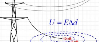
If the obtained values are small, there will be no harm to health. However, as you move away from the equipment grounding point, in this case the U value will increase and reach a maximum where the area of electricity spreading from this grounding point ends.
The presence in the area of current spreading when the wire touches the ground is dangerous for a person to be injured by step voltage. If you experience discomfort when trying to step, you must reduce the step distance to a minimum. You can get out of the danger zone either by jumping on one leg, or by walking without lifting your soles off the ground and placing your feet as close to one another as possible.
Attention! Touch voltage above 42 V AC is dangerous to human life and health. If direct electricity reaches 120 V or more, touching it also poses a significant health hazard.
Violation of the insulation of live cables or wires and simultaneous contact of the human body with grounded metal structures and an area with damaged insulation will lead to electrical injury.
Danger from touch voltage
What is touch voltage, its norms, calculation and protective measures
When working with electrical installations in an alternating current circuit, the possibility of feeling its influence cannot be completely excluded. The cause may be accidental contact with live elements or indirect factors. We have already talked about one of them (step voltage) in detail on the pages of our website. This article will discuss another type of indirect effect of electric current on a person, called touch voltage.
What is “touch voltage”?
In electrical safety, this term refers to the potential difference between two points in an electrical circuit that occurs at the moment a person touches them simultaneously.
This situation can arise as a result of a violation of the insulation of current-carrying circuit elements, their short circuit to electrically conductive surfaces, which leads to the formation of dangerous zones of current flow.
Contact with such a surface is called indirect contact with the housing or electrically conductive elements (depending on the electrical installation design).
Rice. 1. Example of indirect touch
In such cases, the degree of exposure to electric current depends on both the resistance of the human body (R) and the magnitude (Upr). Let us assume in this case that R = 800 Ohm, Upr is close to the phase voltage (230 V). Using Ohm's law, it is easy to calculate the amount of current in the resulting electrical circuit: Ipr=Upr/R= 220/800 = 287.5 mA. This value is several times higher than the permissible standards.
In most cases, indirect contact is single-pole, that is, in this case, the threat is posed by phase rather than line voltage, which is 1.73 times higher. But this is little consolation, since electric shock can still be fatal.
The danger of indirect touching lies in the fact that the risk of its occurrence, in most cases, does not depend on human actions, unlike direct touching, which can occur through negligence, as a result of an error or non-compliance with safety regulations.
Ways to reduce the danger
GOST 12.1.038-82 (2001) dated March 01, 2022 is the main regulatory document that is used to guide when taking the necessary measures. This GOST considers the standards for the maximum possible values of touch voltage.
Induced voltage
To ensure electrical safety for people, the following steps apply:
- installation of protective grounding devices;
- zeroing of working equipment;
- installation of potential equalization systems (EPS);
- fencing and installation of protective shields on live equipment;
- use of reduced voltage in work in areas with increased danger and especially dangerous ones;
- providing personnel with collective and individual protection items: insulated power tools and dielectric means;
- use of residual current devices (RCDs) and alarms.
Grounding devices are designed to protect against phase-to-frame short circuits. They are installed to reduce the voltage between the ground and live parts of electrical installations.
Important! All metal parts of installations, engines, switchboards, consoles, metal housings of power tools and other elements accessible to touch that can conduct current are subject to mandatory grounding.
To protect against extraneous voltage in places where connection to the ground loop is impossible, grounding is used. Using a separate conductor, the device body is connected to a grounded zero. When a phase hits it through this conductor, the short-circuit protection device is triggered.
To reduce the risk of electric shock to people, industrial and domestic premises are equipped with potential equalization systems (PES). They are basic (OSUP) and additional (DOSUP). The main system is independent and provides potential equalization on accessible metal surfaces of the equipment. DOSUP takes additional measures to reduce the level of potential difference in particular cases.
The implementation of protective fences and the installation of shields protect people from accidental contact with live parts. As an additional measure, warning posters are posted on the fences.
In places with increased danger and particularly dangerous work can only be done with power tools whose supply voltage is not higher than 42 V. For this, step-down transformers are used.
Information. Rooms with increased danger include those where there are: a chemically aggressive environment, high humidity (more than 70%), elevated temperature (above 500C), accessible contact with metal parts or concrete floors.
Collective and personal protective equipment (PPE) includes: dielectric mats and stands, boots, galoshes, gloves and tools with insulating handles. The use of such protective kits reduces the risk of touch voltage.
RCD - residual current devices installed in the apartment allow you to control the occurrence of current leaks and dangerous voltage in places with increased danger (kitchen, bathroom). When dangerous quantities appear, the device turns off the power supply until the cause of their occurrence is eliminated.
A way to reduce the risk of electrocution
What is touch voltage and what does its magnitude depend on?
Electric current does a lot of useful work and the life of a modern person is impossible without it, but in addition to benefit, it can also cause harm. Electric shock can cause pain, burns and even death. Electrical safety is a very broad topic that is covered in more than one publication. In this article we will talk about what touch tension is and what is meant by it.
Definition of the concept
When a person or animal touches with his body exposed live parts, the body of a device that for some reason is under potential, a cable with damaged insulation, etc., while he himself is standing on the ground, then the potential difference between the point of contact and the ground is called voltage touch.
In other words, this is the voltage under which two exposed conductive parts are not connected to each other.
The conditions for occurrence are as follows - the enclosures of electrical appliances are usually grounded, but damage to the insulation of electrical equipment inside these enclosures causes touch voltage to appear when you put your hand on the metal part of the enclosure and associated metal parts.
Is touch voltage safe?
Let's start with what exactly is dangerous? Tension in itself is not particularly dangerous. Electric current has destructive and dangerous effects. However, the likelihood of receiving an electric shock depends on the voltage.
An alternating current voltage of 42 Volts is considered safe; previously it was considered 36 V. It is used for arranging portable lamps and for powering power tools, when working in hard-to-reach places, in garages, basements, wet rooms, as well as in places of temporary work.
But touch tension and safe tension for a person are slightly different things.
The effect of electric current on a person is destructive, it can cause fibrillation contraction of the heart and death, therefore the values of permissible voltages and currents are prescribed in regulatory documents. According to the standards described in GOST 12.1.038-82, touch voltage under normal conditions (without accidents) should not be greater than:
- with alternating current with a frequency of 50 Hz – 2 V (current – 0.3 mA);
- with alternating current with a frequency of 400 Hz – 3 V (current – 0.4 mA);
- at direct current – 8 V (current – 1 mA);
These are the maximum permissible values for exposure up to 10 minutes per day. It is worth noting that for people who work at temperatures greater than 25°C and relative humidity greater than 75%, these values are reduced by 3 times.
Since touch voltage is measured between the place of a person’s position on the ground (his contact with a conductive surface) and the place of contact with electrical equipment, it follows that it depends on the location in the room, more precisely relative to the grounding point. The farther you stand at the moment when you touched a dangerous device, on whose body there was potential (from the grounding point), the greater the value of the touch voltage.
A few more definitions are worth noting:
- Spread zone. This area on the ground, beyond which the potential that arises when a ground fault current flows, is equal to zero. Outside the spreading zone, the touch voltage is numerically equal to the potential on the surface you touch.
- Step voltage. This is the voltage between two points on the ground (soil) around the point where the live part is shorted to ground. The idea is that if a high-voltage cable falls near you, you need to move away from it in small incremental steps, without lifting your feet from each other and from the ground, thus reducing the distance between steps. The potential from the ground fault point decreases exponentially. This means that at the point of the ground fault it is equal to the potential of the shorted conductor, and outside the spreading zone it is zero. Then the voltage between these two points is equal to the voltage of the closed cable.
You should have noticed that touch voltage, spread zone and step voltage are all related.
Ways to reduce the danger
Let's figure out how to protect yourself from touch tension. To reduce the risk of potential occurring on the housings of electrical appliances, it is necessary, firstly, to ensure reliable grounding. Moreover, the resistance of the transition contact of the ground electrode (metal connection) should not exceed 0.01 Ohm. The connection point must be securely bolted or welded and must be checked regularly.
Secondly, before turning on devices after a long period of inactivity and generally old ones (more than 10 years), you need to check the quality of the insulation of wires and cables; for this, use a megohmmeter. As a guide, the insulation resistance should be 1 MOhm (megaohm) per 1 kV. For an electrical network of 220-380 Volts, 0.5 MOhm is sufficient.
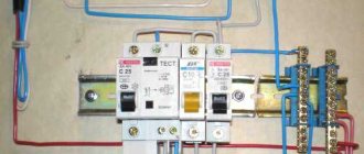
To reduce the possibility of electric shock, it is necessary to install an RCD or a circuit breaker. Their purpose is to protect people from electric shock. But here we need a TN-CS or TN-S grounding system, that is, the network must have separate PE and N wires, but not a combined neutral wire. It is necessary to comply with the protection requirements, otherwise the RCD will not perform its tasks correctly.
Calculation of touch voltage
In networks with an isolated neutral, the touch voltage is calculated using the formula:
Uprik=Fland-Fcorps
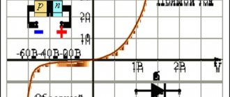
The ground potential decreases with distance from the grounding point, this is illustrated in the picture above. In the case where there is only one ground electrode, the most dangerous contact will be with the body of the device that is located farthest from the ground electrode. Therefore, the grounding circuit must unite the entire area of the room and ensure uniform potential equalization.
The complete formula, taking into account all resistances (touching, spreading zones), is as follows:
U=Фзa1a2,
Where a1 is the contact U coefficient, it is influenced by the shape of the potential drop curve, a2 is the contact coefficient, takes into account the resistance to spreading over the area on which the person stands, shoes, and phase isolation from the ground.
In networks with a solidly grounded neutral, when a person is exposed to a voltage lower than linear (with linear 380V, phase is 220V), the current flowing through the human body is limited by the resistance of shoes, floor (ground) and body.
Measurement methods
When introducing and routinely checking the condition of electrical installations, touch voltage is measured, let's learn about the measurement procedure. First, disconnect the neutral wire from the electrical panel. Then the resistance is measured with a milliohmmeter or a ground loop meter, type MRU-101.
Then a circuit is assembled, where at a distance of at least 25 m from the ground electrode (number 2 in the figure), a pin is installed to a depth of 25-30 cm and an electrode similar to a human foot (indicated by number 3 in the figure). Voltage V1 is applied between the ground electrode and the pin. Voltmeter V2 – touch voltage.
A 1000 Ohm resistor is installed in parallel to it (simulating the resistance of the human body) and a disconnector (when it is closed, a measurement is performed).
This is what an electrode that imitates a human foot looks like:
Where 1 is a cloth pad (wet), 2 is a conductive copper plate, 3 is a dielectric, 4 is a handle, 5 is a wire connected to the meter.
Calculation of touch voltage
By performing calculations, the possible value of the current in case of contact is determined. For calculations, two electrical network diagrams are considered:
- circuit with solidly grounded neutral;
- system with isolated neutral.
Electrical voltage
In the first case, when a person is exposed to phase voltage (220 V), the amount of current through it is restrained by the resistance of the circuit: phase - body - shoes - floor (ground). Based on this, the formula looks like:
Ich = Uph/(Rch + Rob + Rp + R0) ≈ Uph / Rch,
Where:
- R0 – resistance of the transformer neutral protective conductor, R0 ≤ 10 Ohm;
- Uph – phase voltage;
- Rch – human resistance;
For linear voltage, the flow current is calculated using the formula:
Ich = Ul/√3*( Rch + Rob + Rp + R0).
In the second case, where the neutral is isolated, they work with the formulas:
- Ich = Ul/Rch – for the moment of two-phase contact;
- Ich = 3Uph/(3Rch + Riz) – a variant of single-phase contacting, where Riz is the insulation resistance of the phase wires in relation to the ground.
Note! If the ground electrode is singular, then touching the body of the device furthest from it will be the most dangerous.
How is touch current measured?
Touch currents must be measured in accordance with the requirements of the GOST R IEC 60990-2010 standard.
GOST R IEC 60990-2010, which is a fundamental safety standard, established methods for measuring touch current and protective conductor current, which are gradually replacing methods for measuring leakage current in international standards. The international standard provides for the measurement of direct current and alternating current, sinusoidal or non-sinusoidal, that may flow through the human body and through the protective conductor, excluding the following electrical currents [3]:
- touch currents with a duration of less than 1 s;
- currents arising when using medical electrical devices in accordance with GOST R IEC 60601-1-2010;
- alternating current with a frequency of less than 15 Hz;
- AC in combination with DC, since the use of a single multi-terminal network to summarize the effects of combined AC and DC has not been explored;
- electrical currents exceeding the currents selected as electrical burn limits.
The requirements of the standard in question apply to electrical equipment of classes 0, I, II, III. Touch current measurement methods are based on the possible effects of electric current flowing through the human body. Touch current measurements are carried out using special multi-terminal networks, which are an approximate equivalent of the total resistance of the human body.
Kharechko Yu.V. Having analyzed the IEC 60990 standard, I concluded the following [2]:
“The GOST R IEC 60990-2010 (IEC 60990) standard also notes that in the past, electrical standards used two traditional methods to measure leakage current. Either they measured the actual current in the protective conductor, or they used a simple resistor-capacitor multi-terminal network, which is a simple model of the human body. In the latter case, the leakage current was defined as the electrical current flowing through the resistor. IEC 60990 now provides measurement methods for four body responses to electrical current (sensation, response, release and burn), using a more representative model of the human body. »
“This model has been chosen as a generalizable model for most common cases of electric shock. In relation to the path of electric current flow and contact conditions, the international standard uses a human body model that approximates full hand-to-hand or hand-to-foot contact under normal conditions. For small contact areas (for example, touching with one finger), another human body model may be more appropriate. »
Yu.V. Kharechko continues [2]:
“The GOST R IEC 60990-2010 (IEC 60990) standard establishes that of the four indicated reactions of the human body to electric current, sensation, response and release are associated with the amplitude value of the touch current and change with frequency. Traditionally, when considering electrical shock problems, one has dealt with sine waveforms, for which effective measurement values are most convenient. Amplitude measurements are more appropriate for non-sinusoidal waveforms where significant touch current values are expected, but are equally suitable for sine waveforms. »
“Multipoles designed to measure currents of sensation, response and release are weighted by frequency, that is, they take into account the change in the impedance of the human body when the frequency of the electric current flowing through it changes. Electrical burns are related to the effective value of the touch current and are relatively independent of the frequency of the electrical current flowing through the human body. However, for electrical equipment whose touch currents can cause electrical burns, two separate measurements are required, one at the peak value for electrical shock and one at the rms value for electrical burns. »
In Fig. 3–5 of the GOST R IEC 60990-2010 standard [3] (respectively, Fig. 1–3 in this article) show diagrams of three multi-terminal networks that should be used when measuring touch currents for various reactions of the human body to electric current. These multi-terminal devices are designed to measure touch currents in the range from 100 µA (rms value) / 140 µA (amplitude value) to respectively 10 mA / 14 mA DC or AC with a frequency of up to 1 MHz in sine or non-sinusoidal waveforms. The touch current is determined by calculation as the quotient of dividing the corresponding voltage (U1, U2 or U3) by the resistance value RB equal to 500 Ohms. The standard requires that voltages be measured with a voltmeter that has an input impedance of at least 1 MΩ, an input capacitance of no more than 200 pF, and a frequency range of at least 15 Hz to 1 MHz.
When measuring touch currents that can cause electrical burns, a measuring multi-terminal network must be used, the diagram of which is shown in Fig. 1. It is used to measure the effective value of the unweighted (by frequency) touch current IT, equal to:
IT = U1 / 500 ;
When measuring touch currents that cause sensation and response, you should use a measuring multi-terminal network, the diagram of which is shown in Fig. 2. It is used to measure the amplitude value of the weighted (by frequency) touch current, equal to:
IT = U2 / 500 ;
Rice. 1. Measuring multi-port network, unweighted touch current (based on Figure 1 from [2] by Yu.V. Kharechko)
Rice. 2. Measuring multi-port network, weighted touch current for sensation or response (based on Figure 2 from [2] by Yu.V. Kharechko)
Measuring touch currents at which release is possible should be carried out using a measuring multipole shown in Fig. 3. It is used to measure the amplitude value of the weighted touch current, equal to:
IT = U3 / 500 ;
Moreover, this multi-terminal network should be used only in cases where the inability to release is a significant factor taken into account, i.e. if all the following conditions are met:
- the available electric current is alternating current and its limit value specified in the electrical equipment standard exceeds 2.0 mA (rms value) or 2.8 mA (amplitude value);
- electrical equipment has a part that can be grasped by hand;
- It is expected that it will be difficult to let go of the part that can be grasped by the hand due to the flow of electrical current through the person's hand and arm.
Otherwise, a multiport network must be used, the diagram of which is shown in Fig. 2.
Rice. 3. Measuring multi-port network, weighted touch current for release (based on Figure 3 from [2] by Yu.V. Kharechko)
When measuring direct touch currents that do not have ripple or have a ripple of no more than 10%, unless otherwise specified in the electrical equipment standard, any of the three presented multi-terminals should be used. The touch current is:
IT = U1 / 500 ;
The GOST R IEC 60990-2010 standard [3] establishes nine connection diagrams for single-phase and three-phase electrical equipment when measuring touch currents, which model its operation in low-voltage electrical installations corresponding to various types of system grounding. As examples in Fig. 4 and 5 show two diagrams, respectively shown in Fig. 6 and 11 standard.
Kharechko Yu.V. describes the technique for measuring touch current as follows [2]:
“During the tests, terminal “A” of the measuring multi-terminal network must be connected in turn to each accessible part of the electrical equipment. For electrical equipment that has a protective ground connection or a functional ground connection, the “A” terminal of the measuring multi-terminal is connected to the ground terminal of the electrical equipment being tested. When testing Class 0 and Class II electrical equipment, the protective conductor is ignored. The “B” terminal of the measuring multipole must be connected to the grounding device (protective grounding conductor). »
Rice. 4. Test setup: single-phase equipment in a TN or TT system with a star-connected power supply (based on Figure 4 from [2] by Yu.V. Kharechko)
Rice. 5. Test setup: three-phase equipment in a TN or TT system with a star-connected power supply (based on Figure 5 from [2] by Yu.V. Kharechko)
Kharechko Yu.V. continues to specify the technique for measuring touch current [2]:
“Measurement of touch currents should be carried out in normal mode, when all test switches “I”, “n” and “e” are closed, and in several abnormal modes of operation of electrical equipment and its power supply. In particular, the GOST R IEC 60990-2010 standard provides for measurements under conditions of damage to the protective conductor connected to the open conductive part of class I electrical equipment, which is simulated by opening the switch “e”. »
“The standard also requires measurements to be carried out under conditions of damage to the neutral conductor, simulated by opening the switch “n”, and linear conductors, simulated by opening the switches “I”. For single-phase electrical equipment, additional measurements are performed with different connection options for linear and neutral conductors, which are modeled using the “p” switch. »
The GOST R IEC 60990-2010 standard [3] prescribes measuring touch currents under normal operating conditions of electrical equipment and under certain damage conditions that relate only to the power supply system and the low-voltage electrical installation and do not occur in the electrical equipment being tested.
Measurement methods
The measurements are carried out by a visiting team of a special laboratory that has a license to perform such measurements. Work and non-work places are measured. Measurements are carried out at an ambient temperature of 5-400C and air humidity of 35-80%.
Measuring circuit at the workplace
Attention! The workplace is the area of operation of operational personnel within the framework of the regular work process. A non-work place is an area where there may be people who are not performing official duties related to work in electrical installations.
Before making measurements, the neutral conductor is disconnected from the shield to preliminary measure the resistance of the grounding loop. Next, when assembling the measurement circuit, one output of the device is connected to the protective grounding bus, and the second to the current electrode. Maintaining a distance of more than 25 m from the ground electrode, drive the pin into the ground and install a plate on which a load of 50 kg is placed. This is an imitation of a human leg. The soil under the plate is moistened. The voltmeter V monitors the touch voltage, the resistance R = 1 kOhm is equivalent to the resistance of the human body.
When performing measurements at non-working places, the terminal of the T2 device must be connected to the grounding point of the equipment housing located nearby.
The placement of the current electrode must be done so that the artificial reproduction of the phase voltage ground fault circuit is as accurate as possible.
Another measurement method is a circuit using a voltmeter and an ammeter.
The first tests the touch voltage, the second shows the amount of current flowing through the ground electrode. The power source of the measuring circuit is a transformer with an output voltage of 500 V and a rated power of 100 kVA.
Ammeter and Voltmeter Testing
How to determine and test touch voltage
A welding transformer can be used to determine touch voltage. Since measurements can reach large values, a short circuiter (ITK-1) is connected to the current circuit and the state of the current is checked using a pulse voltmeter.
Pulse current measurement circuit
The main NS meters are an ammeter and a voltmeter.
For measurements, a circuit is used where two electrodes are presented in the form of metal plates. They are located on the ground or floor and imitate the soles of a person. The gap between them is 0.8 m (approximate step width). The surfaces should be in water at a depth of 3 cm. A load with a mass of at least 50 kg is placed on the plates.
Touch voltage is determined by the formula U = (Upp x Uph)/Ut, where:
- Upp is the value of the indicator between the plates;
- Uф – numerical characteristic of the network by phase;
- Ut – voltage of the welding transformer on the secondary winding.
Touch voltage detection circuit
Single ground
This is the simplest type of equipment grounding, in which there is no need to construct a special circuit. Nevertheless, it is a very effective protective component that allows the protective shutdown to operate and “bypass” a person who has come under voltage.
Single protective earthing includes:
- grounding electrode 2500 mm long - angle steel 50*50*0.5 mm or pipe with a diameter of at least 4 mm;
- grounding conductor - rolled steel wire with a diameter of at least 0.8 mm outdoors and 0.6 indoors or a steel strip 25 mm wide and 0.5 mm thick;
- The connection point for the grounding conductor is a bolt for connection on the electrical installation body.
As a grounding conductor indoors, it is permissible to use a flexible stranded copper wire of yellow-green color, with a cross-section of at least 2.5 mm. All connections are made using electric welding. The seams are at least 10-15 mm long. Welding areas and metal grounding parts (except for the electrode driven into the ground) are painted with black paint to protect against corrosion.
Important! The minimum grounding resistance for a 220 V network should be no more than 8 Ohms, for a three-phase 380 V line the minimum value of R ≤ 4 Ohms.
The ground electrode is driven or buried into the ground so that its upper part is 0.4-0.5 m below ground level.
TABLE OF CONTENTS
Part 1
1. General provisions 2. Methods for checking the status of the memory 2.1. Checking the implementation of memory elements 2.1.1. Visual check of the memory 2.1.2. Determination of the actual memory circuit 2.2. Checking the connection of grounding conductors with grounded elements, as well as natural grounding conductors with a charger 2.3. Checking the corrosion state of charger elements located in the ground 2.4. Measuring the resistance of chargers of substations and power lines 2.4.1. Measuring the resistance of substation chargers 2.4.2. Measuring the resistance of grounding conductors of overhead line supports 2.5. Measuring touch voltage 2.6. Checking the voltage at the substation charger when a ground fault current drains from it 2.7. Checking the condition of breakdown fuses 2.8. Checking the phase-zero circuit in electrical installations up to 1 kV
with solid neutral grounding
Part 2
3. Determination of the level of interference from external electromagnetic disturbances 4. Safety measures when monitoring the charger 5. Documentation for the charger of an electrical installation 6. Recommendations for repairing and strengthening the charger Appendix 1. Measuring equipment for monitoring the electrical parameters of the charger Appendix 2. An example of determining a real charger circuit using measuring complex KDZ-1 Appendix 3. Selection of the seasonal coefficient, measurement of the electrochemical potential and determination of the presence of stray currents Appendix 4. Determination of the resistance of the artificial grounding system of an electrical installation without taking into account outgoing communications Appendix 5. Numerical calculation of the electrical installation's charger Appendix 6. Passport for the grounding device of the power facility Appendix 7. Protocol for checking the condition of grounding devices
Group grounding
A grounding loop is formed from single grounding conductors. They are placed in one row or in the form of a geometric figure to reduce the overall resistance of the structure. Calculations are made in advance, as a result of which the required number of elements in the circuit is determined.
Information. The distance between adjacent electrodes in the circuit is maintained equal to the length of the electrode. This is due to the fact that the maximum efficiency of a single ground electrode (90%) is achieved by its area of action. The zone includes all points equidistant from it at a distance of its length. The areas of action of the nearest grounding conductors should not intersect.
Ground loop
Protection against indirect contact
The main task of protection against indirect contact is to follow the basic rule of protection against electric shock, to turn off the power to the dangerous circuit in time to avoid injury.
According to the standards of PUE ed. 7 (section 1, chapter 1.7.) and IEC 60 364_4_41 (section 413), protection against indirect contact is the following measures:
1.residual current devices 2.3.4.
Important protective measure
6.Grounding schemes
TN (TN-C, TN-S, TN-CS) – power supply from a source with a solidly grounded neutral and with grounding conductors connected to the neutral.
These grounding systems are historically the most used in Russia and the CIS. We will discuss them in more detail in the following articles. Here briefly, the TN system assumes that the power is supplied from a transformer, the common point of the windings of which is grounded. Grounding of parts of the electrical installation itself (house, entrance, apartment, production) is carried out by connecting the grounding wire to the neutral of the transformer. Depending on the actual point of connection to the neutral, the TN-C, TN-S, TN-CS circuits are divided.
TT – power supply from a source with a solidly grounded neutral and with grounding conductors not connected to the neutral;
This system is not typical for our country. However, it finds application in suburban construction of individual housing construction.
IT – grounding system powered from a source with an isolated neutral.
This grounding system, in its autonomy, stands next to the TT system. In all documents they are described in pairs, separately from the TN system.
It is worth noting that TT and IT systems are more widespread in the West, which is why they are given more attention in the IEC than in the PUE
- pue_7
- pue_6
- pue_6_7
Ehto.ru
Types of electrical injuries
Electrical injuries occur due to the action of an arc or current. There are local or general damage to the body.
With local exposure to electricity on the human body, the following may occur:
- burns;
- metallization of the skin;
- electrical signs;
- burn of the cornea of the eyes;
- mechanical injuries to the skin and soft tissues.
They do not pose a danger to life; treatment of local affected areas of the body is required. The exception is burns - if the percentage of damage to the skin surface is too high, death is possible.
The severity of an electric shock depends on the path the electricity takes through the victim's body. There are five degrees of electric shock, which results in the following consequences:
- weak, involuntary muscle contraction - cramps are barely noticeable;
- convulsions with severe pain;
- lack of consciousness without failure of the heart and respiratory organs;
- lack of consciousness with loss of breathing and heartbeat;
- clinical death.
Note! The outcome depends on how quickly the person is freed from the effects of electricity and how successfully medical care is provided.
Paths of current passing through the human body
Touch current limits
Having analyzed a large amount of regulatory documentation, Kharechko Yu.V. in his book [2] he writes:
“ Information on the effects of electric current flowing through the human body, from which its limit values can be derived, is contained in the technical specification IEC 60479-1. However, despite this, and the fact that the specification or inclusion of certain limit values of touch current is not the scope of the GOST R IEC 60990-2010 (IEC 60990) standard, reference Appendix D “Selection of current threshold values” has been included in this standard. . It provides examples of electrical current limits and their selection that can be used by technical committees when selecting touch current limits for a particular electrical equipment. »
Let's look at examples of electric current limits.
The GOST R IEC 60990-2010 standard [3] notes that the current limit for ventricular fibrillation is not accepted. It is expected that the limits chosen for touch currents will be well below the threshold for ventricular fibrillation.
The approximate average threshold value of the release current1 is specified in the technical specification IEC 60479-1 to be 10 mA rms. A value of 5 mA (RMS) would cover the entire adult population2.
“ Note: 1) The term “release threshold” is defined in the technical specification IEC 60479‑1 as follows: the maximum value of touch current at which the person holding the electrodes can release the electrodes.
Note: 2) The GOST R IEC 60990-2010 standard states that men and women have an average release threshold of 16 mA and 10.5 mA, respectively, and 99.5% of men and women have 9 mA and 6 mA, respectively. The release threshold for children is lower. »
The response threshold3 specified in the technical specification IEC 60479-1 for low frequencies (15-100 Hz) is approximately 0.5 mA rms or 0.7 mA peak for sinusoidal current.
“ Note: 3) The term “response threshold” is defined in the technical specification IEC 60479-1 as follows: the minimum value of touch current that causes involuntary muscle contraction. »
Kharechko Yu.V. in his book [2] focuses on the following:
“The GOST R IEC 60990-2010 standard [3] also notes that touch current can be felt at very small values, such as several microamps. If this current is not accompanied by an unintended reaction resulting in harmful consequences, it is not considered to be a hazardous electrical current. The maximum permissible value of leakage and touch currents for Class II electrical equipment in IEC standards is usually set equal to half the response threshold - 0.25 mA (rms value). Limits less than 0.25 mA rms are specified for some medical applications. »
Appendix D of the GOST R IEC 60990-2010 standard [3] also contains general recommendations for the selection of electric current limits, which are usually expressed in maximum values of direct current and alternating current at frequencies up to 100 Hz. For electrical equipment with parts that can be grasped by hand, the highest electrical current limit is the release threshold.
Between the response and release thresholds, there may be an incidental risk of injury due to surprise or involuntary muscle contraction. However, it is not usually expected that a person will suffer injury directly caused by the flow of electrical current through his or her body. When a release limit is applied to electrical equipment, this electric current can be considered as acceptable under single fault conditions, such as a faulty connection when making a protective earth connection.
Reaction current limits and lower limits are used for electrical equipment for which there is a need to avoid unintended reaction where serious consequences could result (for example, a person falling down a ladder or falling electrical equipment). An electrical current limit of less than 0.25 mA rms or 0.35 mA peak value is set where the user is particularly sensitive or there is a hazard due to environmental or biological reasons.
The GOST R IEC 60990-2010 standard (see Appendix D.3) [3] also states that there is no generally accepted limit value for touch current, which in all cases will not cause electrical burns. According to research, skin burns begin to occur at electric current densities of approximately 300 mA/cm2 to 400 mA/cm2 (rms value).
Regulatory documents limit the maximum permissible values of touch currents for electrical equipment. For example, Table 5A “Maximum Current” of the GOST IEC 60950-1-2014 standard [4], part of which is reproduced below, shows the maximum permissible values of touch current of information equipment. The measurement of touch currents is prescribed to be carried out using a multi-terminal measuring network, the diagram of which is shown in Fig. 4 of the IEC 60990 standard (see Fig. 2 of this article), or using an alternative measuring device, the circuit of which is shown in Fig. D.2 of the GOST IEC 60950-1-2014 standard (Fig. 6 of the current article).
| Equipment type1 | Effective value of the maximum touch current, mA |
| Any | 0,25 |
| Portable equipment | 0,75 |
| Mobile equipment (other than portable, but including transportable equipment) | 3,5 |
| Stationary equipment with detachable connection type A2 | 3,5 |
| All other stationary equipment not subject to the conditions of clause 5.1.73 | 3,5 |
Extract from Table 5A of the GOST IEC 60950-1-2014 standard
Notes to Table 5A of the GOST IEC 60950-1-2014 standard:
1) For this electrical equipment, as erroneously stated in the IEC 60950-1 standard, accessible parts and circuits are not connected to protective earth. That is, electrical equipment is mentioned here that does not have accessible conductive parts and electrical circuits that are subject to protective grounding.
2) Type A plug-in electrical equipment is electrical equipment that is designed to be connected to the supply circuit through a non-industrial plug and socket and/or a non-industrial connecting device.
3) For electrical equipment subject to the conditions of clause 5.1.7, the IEC 60950-1 standard establishes a maximum protective conductor current, which should not exceed 5% of the line conductor current under normal operating conditions.
Clause 5.1.7 of the GOST IEC 60950-1-2014 standard [4] contains requirements for equipment that has a touch current exceeding 3.5 mA (rms value). Such equipment must have a main protective earth terminal and be:
- stationary permanently connected equipment;
- stationary equipment with plug-in type B connection;
- fixed type A plug-connected equipment with a single connection to the a.c. supply circuit, equipped with a separate protective earthing terminal in addition to the main protective earthing terminal, if any. Its installation instructions shall state that this separate protective earth terminal must be permanently connected to the earthing device;
- mobile or stationary equipment with a Type A plug connection for use in a restricted area, with a single connection to the a.c. supply circuit, equipped with a separate protective earthing terminal in addition to the main protective earthing terminal, if applicable. The installation instructions must state that this separate protective earth terminal must be permanently connected to the earthing device;
- fixed type A plug-in equipment with multiple simultaneous connections to an alternating current supply circuit, intended to be used in an area having potential equalization (such as a telecommunications center, specialized computer room or restricted area). The equipment must be provided with a separate, additional protective grounding terminal. Instructions for its installation must require the following conditions:
- the electrical installation of the building must provide means for connection to the protective grounding device and the equipment is connected to these means;
- The service person must check that the socket outlet from which the equipment is to receive its electrical power actually provides connection to the building's protective earthing device. Otherwise, the servicer must make arrangements to install a protective earth conductor from the separate protective earth terminal to the protective earth conductor in the building.
The GOST IEC 60950-1-2014 standard [4] provides some examples of national requirements. In Finland, Norway and Sweden, equipment with a touch current greater than 3.5 mA rms may be:
– stationary equipment with a type A detachable connection, which:
intended for use in a restricted access area where potential equalization is applied, for example in a telecommunications center; has a precaution for permanent connection of the protective grounding conductor; provided with instructions for installation of this conductor by the service person;
– stationary equipment with a detachable connection type B; – stationary, permanently connected equipment.
In Denmark, the specified equipment can only be permanently connected equipment and fixed type B plug-in equipment.
One of the following labels, or a label with similar wording, must be affixed to the AC supply circuit near the point where equipment having a touch current greater than 3.5 mA rms is connected:
| WARNING HIGH LEAKAGE CURRENT GROUNDING CONNECTION REQUIRED BEFORE CONNECTING POWER | WARNING HIGH TOUCH CURRENT GROUNDING CONNECTION REQUIRED BEFORE CONNECTING POWER |
The requirements for measuring touch current given in subsection 5.1 (Touch current and protective conductor current) of the GOST IEC 60950-1-2014 standard [4] are based on similar requirements set out in the GOST R IEC 60990-2010 standard [3]. Touch current is measured using special multi-terminals that simulate the total resistance of the human body. The schematic diagram of the main measuring device is borrowed from Fig. 4 standards GOST R IEC 60990-2010 (see Fig. 2 of this article). This device measures the voltage value U2 in the frequency range from 20 Hz to 1 MHz. The value of touch current IT in amperes is calculated by the formula:
IT = U2 / 500
It is also possible to use an alternative measuring device shown in Fig. D.2 of the GOST IEC 60950-1-2014 standard (Fig. 6), which was developed for earlier editions of this standard. However, its use for measuring touch current is less preferable, since it gives less accurate measurements than the main measuring device if the waveform is non-sinusoidal and the fundamental frequency exceeds 100 Hz.
Rice. 6. Alternative measuring device
Kharechko Yu.V. described in his book [2] the design and operating principle of an alternative measuring device as follows:
“An alternative measuring device is used to measure the effective value of the touch current. This measuring device consists of a magnetoelectric measuring device M, which has a measuring range of 0–1 mA, a rectifier D1-D4 (diode bridge), two additional resistances R1 and RV1, shunted by a capacitor C, which reduces sensitivity to harmonics and other frequencies above industrial frequency. In this case, the following numerical values of the characteristics must be provided at a constant current of 0.5 mA: R1 + RV1 + Rm = 1500 Ohm ± 1% and C = 150 nF ± 1% or 2000 Ohm ± 1% and C = 112 nF ± 1% . The measuring device must also have a measuring range of × 10, which is obtained by bridging the winding of the measuring device with a non-inductive resistor RS. To ensure maximum sensitivity of the device, you need to press the S button. »
To test single-phase equipment used in TN or TT systems having a star-connected power supply, use the test circuit shown in Fig. 5A standard GOST IEC 60950-1-2014 [4], three-phase equipment - in Fig. 5B (Fig. 7 and 8, respectively). These circuits are developed based on Fig. 6 and 11 of the IEC 60990 standard (see Fig. 4 and 5, respectively). In the case of the use of information equipment in low-voltage electrical installations that have an IT system grounding type or are connected to a delta-connected power source, the GOST IEC 60950-1-2014 standard requires the use of other test circuits that meet the requirements of the GOST R IEC 60990-2010 standard.
Rice. 7. Test circuit for touch current of single-phase equipment in a TN or TT system with a star-connected power supply
An isolation transformer T, intended to provide protection, is not required to be used for testing. The equipment port (port in the figures) intended for its connection to the telecommunications network is not connected to the specified network during testing. If single-phase equipment is connected between two line conductors, it is tested using a three-phase test circuit such as in Fig. 8.
Rice. 8. Test circuit for touch current of three-phase equipment in a TN or TT system with a star-connected power supply
During testing, the “B” terminal of the multi-terminal measuring network is connected to the grounded (neutral) conductor of the power source. Clamp “A” of the measuring multipole is connected as follows. For equipment having a protective or functional earth connection, the "A" terminal is connected through the measuring switch "s" to the main protective earth terminal of the equipment, with the protective earth conductor switch "e" open. The test is also carried out on the entire equipment, with terminal "A" connected through test switch "s" to each ungrounded or non-conductive accessible part and each ungrounded accessible circuit in turn, with switch "e" closed. The terminal “A” of the measuring multipole is connected to the non-conducting part using metal foil 100 × 200 mm, which is placed on this part. The foil test simulates contact between the equipment and a human hand.
Single-phase equipment is additionally checked with reverse polarity (switch “p1”). Three-phase equipment is also tested with reverse polarity (switch “p1”), with the exception of equipment that is sensitive to phase sequence.
Information equipment generates touch currents in the telecommunication networks and cable distribution systems connected to it, which the GOST IEC 60950-1-2014 standard [4] limits to 0.25 mA (rms value). The equipment is checked using the test circuits shown in Fig. 7 and 8.
For class I electronic equipment, the requirements of section 9 “Electric shock hazard under normal operating conditions” of the GOST IEC 60065-2013 standard [5] set the maximum permissible touch current value to 3.5 mA. The measurement of touch currents is prescribed to be carried out using a multi-terminal measuring network, the diagram of which is shown in Fig. 4 standards GOST R IEC 60990-2010 (see Fig. 2). The same maximum value of touch current is provided for by GOST IEC 60065-2013.
Subsection 10.3 “Touch current, protective conductor current and electrical burn” of the GOST IEC 60598-1-2017 standard [6] states that the touch current or protective conductor current that occurs during normal operation of the luminaire should not exceed the values established in the table 10.3 “Limit values of touch current or protective conductor current and electrical burns.” For all class II and class I luminaires with a rated current up to and including 16 A, equipped with a plug connected to an ungrounded socket outlet, the international standard sets a maximum touch current limit of 0.7 mA (amplitude value). The measurement of touch currents is prescribed to be carried out using multi-terminal measuring networks, the diagrams of which are shown in Fig. 4 and 5 of the GOST R IEC 60990-2010 standard (see Fig. 2 and 3), on the test setup shown in Fig. 6 of the GOST R IEC 60990-2010 standard (see Fig. 4).
Clause 18.5.1 “Touch current” of the GOST IEC 61558-1-2012 standard [7] states that the measured touch current must be equal to or less than in table 8b “Limit values for currents”. In this table, the maximum permissible touch current value is set to 0.5 mA rms for all class I and class II transformers equipped with a plug in accordance with technical report IEC 600831. For other transformers, the standard specifies the maximum value of the protective conductor current. The measurement of touch currents is intended to be carried out in a test circuit, the diagram of which is shown in Fig. 6 of the GOST R IEC 60990-2010 standard (see Fig. 4). As a measuring multi-port network, a multi-port network should be used, the diagram of which is shown in Fig. 4 standards GOST R IEC 60990-2010 (see Fig. 2 of this article).
Prevention
In a timely manner, at least 2 times a year, it is necessary to measure the protective grounding and the phase-zero loop at workplaces.
Eliminate the following causes of electrical injuries:
- failure to comply with safety regulations;
- being near a broken wire;
- contact with exposed parts of electrical installations under power;
- touching parts of equipment that suddenly become energized;
- touching elements of electrical appliances with damaged insulation.
Electrical safety training must be carried out at workplaces.
When is it necessary to measure touch voltage?
Tests are usually carried out in the following cases:
- On the eve of putting objects into operation.
- After activities related to current or major repairs of electrical installations and grounding devices, as well as electrical equipment.
- After planned work to modernize grounding devices and electrical equipment.
- According to the plan established by the management of the facilities, which is carried out at least once every 6 years.
- When connecting additional electrical installations, equipment and additional lines.
- After a decision of the court or supervisory authorities.
Weather and external conditions
Grounding connections are tested in winter during the period of greatest freezing of the soil and in summer when the soil is most dry at the locations of the protective contours. The resistance value of the grounding device, which means its effectiveness, depends on the condition of the soil. If we take into account that the potential difference from static electricity during a thunderstorm can reach values above a thousand volts, then the potential equalization system (EPS) must withstand such loads.
It is impossible to completely eliminate potential differences. There is always a danger of exposure to touch voltage. Compliance with safety precautions and a set of protective measures will help reduce the risk of electric shock to a minimum.