Zener diode refers to one of the used radio-electronic elements. Each more or less high-quality power supply contains a voltage stabilization unit, which can change when the load resistance changes or when the input voltage deviates from the nominal value.
Voltage stabilization is performed mainly to ensure normal operation of the remaining radio elements of the device, for example microcircuits, transistors, microcontrollers, etc.
Zener diodes are widely used in low-power power supplies or in individual units, the power of which rarely exceeds tens of watts.
The main advantage of zener diodes is their low cost and size, so they still cannot be replaced by integrated voltage stabilizers such as LM7805 or 78L05, etc.
A zener diode is very similar to a diode because its semiconductor crystal is housed in a similar package.
The conventional graphic designation of a zener diode on electrical circuit drawings is also similar to the designation of a diode, only on the cathode side a short horizontal line is added, directed towards the anode.
The principle of operation of a zener diode
Let's consider the principle of operation of a zener diode using the example of its connection circuit and current-voltage characteristic. To perform its main function, the zener diode VD is connected in series with a resistor Rb and together they are connected to a source of unstabilized input voltage Uin. The already stabilized output voltage Uout is removed only from pins 2, 3 VD. Therefore, the load Rн is connected to the corresponding points 2 and 3. As can be seen from the diagram, VD and Rb form a voltage divider. Only the resistance of the zener diode does not have a constant value and is called dynamic, since it depends on the amount of electric current flowing through the semiconductor device.
The voltage Uin supplied to the zener diode from the resistors must be at least a couple of volts higher than the output voltage Uout, otherwise the semiconductor device VD will not open and will not be able to perform its main function.
Let's say that at some arbitrary point in time at outputs 1 and 3 the value of Uin began to increase. The following processes will begin to occur in the circuit. As the voltage increases, according to Ohm's law, the current will begin to increase, let's call it the input current Iin. As the current increases, the voltage drop across the resistor Rb will increase, and at VD it will remain unchanged (this will be explained further in the characteristic), therefore Uout will remain at the same level. Consequently, the increase in input voltage will drop or be extinguished by resistor Rb. Therefore, Rb is called damping or ballast.
Now, let’s say the load has changed, for example, the resistance Rн has decreased, and the current In will increase accordingly. In this case, the current flowing through the zener diode Ist will decrease, and Iin will remain virtually unchanged.
How to distinguish a stabilization diode from a conventional semiconductor
Very often people wonder how they can distinguish a zener diode from a standard semiconductor, because, as we found out earlier, both of these elements have almost identical symbols on the electrical circuit and can perform similar functions. The easiest way to distinguish a stabilization semiconductor from a regular one is to use a multimeter attachment circuit. With its help, you can not only distinguish both elements from each other, but also identify the stabilization voltage, which is characteristic of a given SMD (if it, of course, does not exceed 35V). The multimeter attachment circuit is a DC-DC converter, in which there is galvanic isolation between the input and output. This diagram looks like this:
Multimeter attachment circuit
In it, a generator with pulse-width modulation is implemented on a special microcircuit MC34063, and to create galvanic isolation between the measuring part of the circuit and the power source, the control voltage should be removed from the primary winding of the transformer. For this purpose there is a rectifier on VD2. In this case, the value for the output voltage or stabilization current is set by selecting resistor R3. A voltage of approximately 40V is released at capacitor C4. In this case, the tested SMD VDX and the stabilizer for current A2 will form a parametric stabilizer. The multimeter, which is connected to terminals X1 and X2, will measure the voltage at this zener diode. When connecting the cathode to the “-” and the anode to the “+” of the diode, as well as to the asymmetrical SMD of the multimeter, the latter will show a slight voltage. If you connect in reverse polarity (as in the diagram), then in a situation with a conventional semiconductor, the device will register a voltage of about 40V.
Here the T1 transformer will be wound on a torus-shaped ferrite core with an outer diameter of 23 mm. Such winding 1 will contain 20 turns, and the second winding will contain 35 turns of PEV 0.43 wire
In this case, it is important to lay the turn to the turn when winding. It should be remembered that the primary winding goes on one part of the ring, and the second on the other. When setting up the device, connect a resistor instead of smd VDX
This resistor should have a value of 10 kOhm. And resistance R3 needs to be selected in order to achieve a voltage of 40V on capacitor C4. This is how you can find out whether you have a zener diode or a regular diode.
Volt-ampere characteristic of a zener diode
The current-voltage characteristic (volt-ampere characteristic) of a zener diode is similar to the current-voltage characteristic of a diode and has two branches: forward and reverse. The forward branch is the working one for the diode, and the reverse branch characterizes the operation of the zener diode, so it is connected to the electrical circuit in the opposite direction (cathode to positive and anode to negative) compared to the diode. Therefore, I call a zener diode a reference diode , and the power source with this semiconductor element is called a reference voltage source . We will also use this terminology.
On the reverse branch of the current-voltage characteristics of the reference diode, we highlight two characteristic points 1 and 3. Point 1 corresponds to the minimum value of the stabilization current, which is within units of milliamps. If the current flowing through the zener diode is below point 1, then it will not be able to perform its functions (it will not open). If the current exceeds point 3, the reference diode will overheat and fail. Therefore, the optimal point in most cases will be the point in the middle of the reverse branch of the current-voltage characteristic, that is, point 2. Then, when the current changes within a wide range (see the Y axis), point 2 will change its position, moving up or down along the reverse branch, and the voltage will change slightly (see X axis).
A little more about the module and how it works
This is a semiconductor diode that has the property of producing a certain voltage value regardless of the current supplied to it. This statement is not completely true for absolutely all options, because different models have different characteristics. If you apply a very strong current to an SMD module (or any other type) that is not designed for this purpose, it will simply burn out. Therefore, the connection is made after installing a current-limiting resistor as a fuse, the value of the output current of which is equal to the maximum possible value of the input current to the stabilizer.
Schemes for connecting a zener diode and a stabilistor to a circuit
It is very similar to an ordinary semiconductor diode, but has a distinctive feature - its connection is done in reverse. That is, the minus from the power source is supplied to the anode of the zener diode, and the plus to the cathode. Thus, a reverse branch effect is created, which provides its properties.
A similar module is a stabistor - it is connected directly, without a fuse. It is used in cases where the parameters of the input electricity are precisely known and do not fluctuate, and the output also produces an exact value.
Back-to-back, parallel, series connection of zener diodes
To increase the stabilization voltage, two or more zener diodes can be connected in series. For example, you need to get 17 V at the load, then, if the required rating is not available, support diodes of 5.1 V and 12 V are used.
Parallel connection is used to increase current and power.
Zener diodes are also used to stabilize alternating voltage. In this case, they are connected in series and counter.
During one half-cycle of alternating voltage, one zener diode operates, and the second operates like a regular diode. In the second half-cycle, semiconductor elements perform opposite functions. However, in this case, the shape of the output voltage will be different from the input voltage and will look like a trapezoid. Due to the fact that the reference diode will cut off a voltage exceeding the stabilization level, the tops of the sine wave will be cut off.
Main characteristics
The passport of the stabilizing diode indicates the following parameters:
- Rated stabilization voltage Ust
. This setting is selected by the device manufacturer. - Operating current range
. Minimum current – the current value at which the stabilization process begins. Maximum current is the value above which the device is destroyed. - Maximum power dissipation
. In low-power elements this is the nameplate value. In the passports of high-power zener diodes, to calculate the cooling conditions, the manufacturer indicates: the maximum permissible temperature of the semiconductor and the coefficient of thermal resistance of the housing.
In addition to the parameters indicated in the passport, zener diodes are characterized by other quantities, including:
- Differential resistance
. This property determines the instability of the device in terms of supply voltage and load current. The first drawback is eliminated by powering the stabilizing diode from a direct current source, and the second by connecting a DC buffer amplifier with an emitter follower between the zener diode and the load. - Temperature coefficient of voltage
. In accordance with the standard, this value is equal to the ratio of the relative change in stabilization voltage to the absolute change in outside temperature. In non-heat-stabilized zener diodes, when heated from +25°C to +125°C, the stabilization voltage shifts by 5-10% from the original value. - Drift and noise
. These characteristics are not defined for conventional zener diodes. For precision devices they are very important properties. In conventional (non-precision) zener diodes, noise is created by: a large number of foreign impurities and crystal lattice defects in the region of the pn junction. Methods for reducing noise (if necessary): protective passivation with oxide or glass (impurities are directed deep into the crystal) or by moving the pn junction itself deep into the crystal. The second method is more radical. It is in demand in low noise diodes with a hidden structure.
Marking of zener diodes
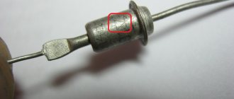
Markings are applied to the zener diode housing in the form of numbers and letters (or letters). There are fundamentally two different types of markings. The zener diode in a glass case has the usual markings for us, directly indicating the rated stabilization voltage. The numbers can be separated by the letter V, which acts as a decimal point. For example, 5V1 means 5.1 V.
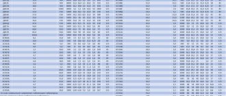
A less clear way of marking consists of four numbers and a letter at the end. If you are not an experienced radio amateur, then you can’t do without a datasheet. For example, let's decipher the parameters of the reference diode of the 1N5349B series. We are most interested in the first column, which shows the rated voltage of 12 V. The second column is the rated current value - 100 mA.
The cathode of a zener diode of any type is indicated by a black or blue ring, which is applied to the body from the side of the corresponding terminal.
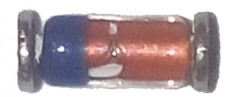
Marking of SMD zener diodes
The most widely used reference diodes are in a glass case and in a plastic case with three terminals. The SMD marking of a zener diode in a glass case consists of a colored ring, the color of which indicates the parameters of this semiconductor device.
If you come across an SMD zener diode with three terminals, then you should know that one terminal is a “dummy”, that is, it is not used and is used only for securely fixing the element on the printed circuit board after soldering. The anode and cathode of such an instance are most easily determined using a multimeter.
Zener diode power dissipation
The power dissipation of a zener diode Pst characterizes its ability not to overheat above a certain temperature for a long time. The higher the Pst , the more heat the semiconductor device can dissipate. Uin and the smallest values of Rb and In are substituted into the formula below :
There are a number of standard ratings for this parameter: 0.3 W, 0.5 W, 1.3 W, 5 W, etc. The larger Pst, the larger the dimensions of the semiconductor device.
How to check zener diode
You can check the zener diode for serviceability quite simply and quickly using a simple multimeter. To do this, the multimeter should be switched to the “continuity” mode, usually indicated by a diode sign. Then, if we touch the anode with the positive probe of the multimeter, and the cathode with the negative probe, then on the display of the measuring device we will see a certain value of the voltage drop across the pn junction. Since direct voltage is applied to the semiconductor device (see the direct branch of the current-voltage characteristic), the reference diode will open.
Now, if the probes of the multimeter are swapped, thereby applying reverse voltage to the terminals of the semiconductor device (see the reverse branch of the current-voltage characteristic), then it will be locked and will not conduct current. The meter display will show a unit, indicating infinitely high resistance.
If in both cases the multimeter shows one or rings, then the zener diode is unusable.
What is a diode and what is it for?
First of all, let's consider the classification of radioelements. Since vacuum and gas-filled diodes are rather exotic, we will consider only semiconductor devices.
Classification by purpose:
Rectifiers. The most common element type. Used to obtain direct current from alternating current. For this purpose, special rectifier circuits are used - bridges.
Rectifier assemblies are so popular that they are produced immediately in finished form; the diodes have a common body and four contacts with markings.
Detector. The ability of the part to detect a signal is used. Mainly used in radio receivers. Many radio amateurs are familiar with the term “detector receiver”. Its operation is based on a detector diode.
Pulse. Based on the name, they are used in pulse circuits.
Mixing. Used in systems for converting high-frequency currents into intermediate-frequency signals.
Restrictive. They are used to build circuits to protect equipment from power surges.
Multiplying. Their scope of application is voltage multipliers.
Generating. Used in frequency generators.
Tuning and parametric. Used in circuits with controlled characteristics to configure and maintain parameters.
Depending on the purpose, diodes are:
- Low frequency;
- High frequency;
- For working with ultra-high frequencies (microwave).
Design classification:
Schottky diode.
Metal is used as a semiconductor, instead of the classic pn junction. Due to this, the diode has a negligible voltage drop at forward current. The widespread use of this design is limited by a significant drawback - with a significant reverse current, the diode quickly fails. This feature is taken into account when checking it.
How to test a Schottky diode? Testing with a multimeter in the “diode check” mode can show a positive result, even if the semiconductor is broken. It is necessary to measure the resistance between the working electrodes in direct and reverse connection in the “continuity” mode.
The tester shows low resistance in one case, and infinitely high in the other. This diode is fine.
If you suspect a breakdown, take a measurement in the “20 kOhm” range. The resistance to reverse current must be infinitely large. If the value is 1-2 kOhm, the diode is faulty.
Watch the video on the topic: “How to test a Schottky diode with a multimeter.”
Zener diode. The ability to produce stable currents in breakdown mode is a feature of the diode, which is used in voltage stabilizers. In this case, the design flaw is used as the main characteristic. How to check a zener diode with a multimeter? Just like a regular diode. The tester voltage is not capable of organizing a breakdown with reverse current.
Stabistor. The purpose is the same as that of a zener diode, but the dependence of voltage on current is less. Therefore, stabistors are used for lower voltages.
Gunn diode. These parts do not have a pn junction at all in the semiconductor crystal. Its operation is based on the intrinsic effects of a single crystal, in contrast to the transition in a classical diode. Used in microwave ranges
Attention! Testing a diode with a multimeter is impossible. Microwave stands are used for this. Varicap
Some kind of mixture of a diode and a capacitor. The capacitance depends on the reverse voltage of the pn junction. Used in radio communications, oscillatory circuits are built on them
Varicap. Some kind of mixture of a diode and a capacitor. The capacitance depends on the reverse voltage of the pn junction. They are used in radio communications; oscillatory circuits are built on them.
Photodiode.
When light energy hits a sensitive element, a potential difference occurs in the pn junction. By closing the circuit, we receive an electric current. The principle of photodiodes is applied in solar cells of power plants. These elements are widely used in light and motion sensors.
How to check a photo diode with a tester? Connect to the electrodes in constant voltage measurement mode and send a powerful light to the crystal. The voltage value will appear on the scale.
Light-emitting diode.
Let's look at this element in more detail. The element works in the same way as a conventional semiconductor diode. Passes current in only one direction. However, its crystal begins to emit light at a certain current. To enhance brightness, the pn junction is coated with a phosphor. As a result, the light intensity can reach tens of lumens on a single chip.
By selecting different materials, you can get any spectrum - from infrared to visible (different colors), and ultraviolet.