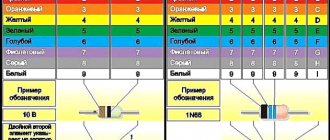
Color coding of diodes in SOD-123 packages
Diodes in SOD-123 packages are coded with colored rings located on the cathode side. The brands of diodes corresponding to these colors are shown in the table.
| Stripe on the cathode | Device |
| Red | BA620, BB620 |
| Yellow | BA619, BB619 |
| Green | BA585 |
| Blue | BA582, 583, 584 |
| White | BA512, 515, BB515, 811 |
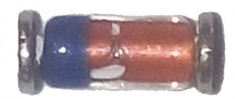
Color coding of diodes in SOD-80 packages
The SOD-80 body, also known as MELF, is a small glass cylinder with metal leads.
Examples of diode markings.
Marking 2Y4 to 75Y (E24 series) BZV49 1W silicon zener diode (2.4 – 75V) Marking C2V4 to C75 (E24 series) BZV55 500mW silicon zener diode (2.4 – 75V)
The cathode terminal is marked with a colored ring.
Marking of devices with colored rings.
| Cathode output | Device |
| Black | BAS32, BAS45, BAV105 LL4148, 50, 51,53, LL4448 BB241,BB249 |
| Black and Kochichnevy (Black Brown) | LL4148, LL914 |
| Black and orange (Black Orange) | LL4150, BB219 |
| Brown and green | LL300 |
| Brown and black | LL4448 |
| Red | BA682 |
| Red and orange | BA683 |
| Red and green | BA423L |
| Red and White | LL600 |
| Orange and Yellow | LL3595 |
| Yellow | BZV55,BZV80,BZV81 series zeners |
| Green | BAV105, BB240 |
| Green and black (Green Black) | BAV100 |
| Green and nomadic (Green Brown) | BAV101 |
| Green and red (Green Red) | BAV102 |
| Green and orange | BAV103 |
| Gray | BAS81, 82, 83, 85, 86 |
| White | BB219 |
| White and green (White Green) | BB215 |
Some SMD diodes in MiniMELF (SOD80 / DO213AA / LL34) or MELF (DO213AB / LL41) cylindrical packages are often marked with colored stripes (the first stripe closest to the edge is located at the cathode) in accordance with the table on the left.
Having a radio-electronic laboratory at home, you can make a variety of devices for electrical equipment or the devices themselves, which will allow you to significantly save on the purchase of equipment. An important element of many electrical circuits of devices is the zener diode.
Such an element (smd, smd) is a necessary part of many electrical circuits. Due to its wide range of applications, the zener diode has different markings. The markings applied to the body of such a diode provide detailed, but encrypted, information about this element. Our article today will help you understand what color markings are found on the housing (glass or not) of imported zener diodes.
Except for diodes
A billion modifications of diodes have been created based on pn junctions. This includes varicaps, zener diodes and even thyristors. Each family has its own characteristics; there are many similarities with diodes. We see three global views:
- today's outdated element base is relatively large in size, clearly visible markings formed by standard letters and numbers;
- glass cases equipped with color symbols;
- SMD elements.
Analogues are selected based on the conditions specified above: power dissipation, maximum voltage, current flow.
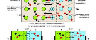
A zener diode is also called a reference diode. Zener diodes are designed to stabilize the output voltage when the input voltage fluctuates or when the load changes ( Fig. 1
).
Rice. 1 – Functional diagram of the zener diode
For example, if you need to get 5 V from the load, and the voltage of the power source fluctuates within 9 V. To reduce and stabilize the voltage supplied from the power source to the required 5 V, zener diodes are used. Of course, you can also use voltage stabilizers; in this case, or are suitable. However, their use is not always justified, so in some cases zener diodes are used.
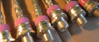
Outwardly, they look like diodes and have the appearance shown in Fig. 2
.
Rice. 2 – Appearance of zener diodes
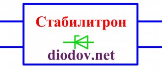
The designation of zener diodes in the diagrams is shown in Fig. 3
.
The principle of operation of a zener diode
Now let's figure out how a zener diode performs voltage stabilization.
The main characteristic of a zener diode, as well as a diode, is the current-voltage characteristic (volt-ampere characteristic). It shows the dependence of the magnitude of the current flowing through the zener diode on the magnitude of the voltage applied to it ( Fig. 4
).
The current-voltage characteristic of the zener diode has two branches.
Rice. 4 – I-V characteristics of the zener diode
The direct branch of a zener diode is practically no different from the direct branches of conventional diodes, and for the latter it will also be working.
The normal operating mode of the zener diode is when it is under reverse voltage. Therefore, the working branch for him will be the reverse branch. It is located almost parallel to the axis of reverse currents. There are two characteristic points on this curve: 1
and
2
(
Fig. 4
), between them there is a working area of the zener diode.
At a certain value of the reverse voltage Ust
,
the p - n
occurs and a significant current already flows through it.
However, when the current changes over a wide range from the value Imin
to
Imax
, the voltage drop across the zener diode
Ust
practically does not change (
Fig. 4
). Thanks to this property, voltage stabilization is achieved.
If the current flowing through the zener diode exceeds the Imax
, then the semiconductor structure will overheat, thermal breakdown will occur and the zener diode will fail.
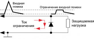
To power supply Uip
The zener diode is connected through a current-limiting resistor
Rogr
, which serves to limit the current flowing through the zener diode, and also, together with it, forms a voltage divider (
Fig. 5
).
Rice. 5 – Zener diode connection circuit
Please note that, unlike a diode, the zener diode is connected in the opposite direction, i.e., “+” of the power supply is supplied to the cathode, and “-” to the anode.
R
n
is connected to the zener diode terminals , at the terminals of which it is necessary to maintain a stable voltage.
The process of voltage stabilization is as follows. I increases
, and consequently the current
Ist
flowing through the zener diode
VD
, and the voltage drop across the current-limiting resistor
R limit
. In this case, the voltage on the zener diode and, accordingly, on the load remains almost unchanged.
I is redistributed
between the zener diode and the load, and the voltage across them practically does not change.
If the load voltage is greater than the stabilization voltage of the zener diode, then several zener diodes connected in series are used. For example, if you need to get 10 V of a stable voltage, then in the absence of the required zener diode, you can connect two 5 V zener diodes in series ( Fig. 6
).
Rice. 6 – Series connection of zener diodes
Zener diodes are also successfully used in automation systems as sensors that respond to voltage changes. For example, if the voltage exceeds a certain value, the zener diode will open and current will flow through the relay coil. As a result, the relay will operate and give a command to other devices or simply signal that a certain voltage level has been exceeded.
In addition to stabilizing direct voltage, using zener diodes you can also stabilize alternating voltage. To do this, use sequential counter
turning on two zener diodes (
Fig. 7
).
Rice. 7 – Circuit diagram for connecting a zener diode to alternating voltage
Only the output will not be an ideal sinusoid, but with cut off tops, i.e. the voltage shape will be close to a trapezoid ( Fig. 8, 9
).
Rice. 8 – Oscillogram of input voltage
Rice. 9 – Voltage oscillogram on the zener diode
Several methods of marking zener diodes are used. Zener diodes in a glass case with flexible leads are marked in the most understandable way. As a rule, numbers separated by the Latin letter “V” are applied to the body. For example, 4
V 7
means that the stabilization voltage is 4.7 V;
9 V 1
– 9.1 V and so on (
Fig. 10
).
Rice. 10 – Marking of zener diodes in glass cases
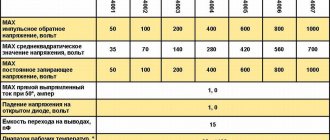
Zener diodes in a plastic case are marked in the form of numbers and letters. By themselves, these numbers do not mean anything, however, with the help of a datasheet they can be easily deciphered. For example, the designation 1N5349B means that the stabilization voltage is 12 V ( Fig. 11
). In addition to voltage, this marking also takes into account other parameters of the zener diode.
Rice. 10 – Marking of zener diodes in plastic cases
A black or gray ring applied to the zener diode body indicates its cathode ( Fig. 12
).
Rice. 12 -
Marking of smd zener diodes
Colored rings are used to mark SMD zener diodes. Similar markings are also used for Soviet non-smd zener diodes. In imported zener diodes, the color ring is applied from the cathode side ( Fig. 13
). To decipher color rings, datasheets or online decryptors are used.
Rice.
13 – SMD zener diode in a glass case
SMD zener diodes with three terminals are also manufactured ( Fig. 14
). One of them is not used. These findings can be determined using a multimeter.
Rice. 14 – SMD zener diode with three terminals
In the absence of a reference book, datasheet or unclear markings, the rated voltage of the zener diode can be determined experimentally. First, using a multimeter, you need to find out the corresponding terminals and connect the zener diode through a current-limiting resistor ( see Fig. 5
). Then apply voltage from a regulated power source. By smoothly changing the supplied voltage, you need to monitor the change in voltage on the zener diode. If the voltage on the zener diode does not change when the voltage of the power source changes, then this will be its stabilization voltage.
The zener diode pins are determined in exactly the same way as . The multimeter should be set to continuity mode and touch the corresponding terminals with probes ( Fig. 15, 16
).
Rice. 15 – Forward voltage
Rice. 16 – Reverse voltage
Under the influence of current flowing through the zener diode, it heats up. The released heat is dissipated into the surrounding space. The more heat a zener diode can dissipate without overheating, the higher its dissipation power and the more current can be passed through it. As a rule, the larger the dimensions of the zener diode, the greater its dissipation power ( Fig. 17
).
Rice. 17 – Power dissipation of zener diodes
Having a radio-electronic laboratory at home, you can make a variety of devices for electrical equipment or the devices themselves, which will allow you to significantly save on the purchase of equipment. An important element of many electrical circuits of devices is the zener diode.
Such an element (smd, smd) is a necessary part of many electrical circuits. Due to its wide range of applications, the zener diode has different markings. The markings applied to the body of such a diode provide detailed, but encrypted, information about this element. Our article today will help you understand what color markings are found on the housing (glass or not) of imported zener diodes.
What is this element of electrical circuits?
Before we begin to consider the question of what color markings exist for such elements, we need to understand what it is all about.
Volt-ampere characteristic of a zener diode
A zener diode is a semiconductor diode, which is designed to stabilize the DC voltage across the load in an electrical circuit. Most often, such a diode is used to stabilize voltage in various power supplies. This diode (smd) has a section with a reverse branch of the current-voltage characteristic, which is observed in the region of electrical breakdown.
Having such an area, the zener diode in a situation where the parameter of the current flowing through the diode changes from IST.MIN to IST.MAX, practically no changes in the voltage indicator are observed. This effect is used to stabilize voltage. In a situation where the RH load is connected in parallel to the SMD, then the diode voltage will remain constant, and within the specified limits of change in the current flowing through the zener diode.
Note! Zener diode (smd) is capable of stabilizing voltages above 3.3 V.
In addition to SMD, there are also zeners, which are turned on when switched on directly. They are used in situations where there is a need to stabilize the voltage in a certain range. A conventional diode can be used when it is necessary to stabilize the voltage in the range from 0.3 to 0.5 V. The region of their forward bias is observed when the voltage drops to 0.7 - 2v. Moreover, it practically does not depend on the current strength. In their work, stabistors use the direct branch of the current-voltage characteristic. They should also be turned on when connected directly. Although this will not be the best solution, since a zener diode in such a situation will still be more effective. Stabistors, like SMD, are often made from silicon. Zener diodes are labeled according to their main characteristics. This marking looks like this:
- UST. This marking indicates the rated voltage for stabilization;
- ΔUST. Indicates the deviation of the voltage indicator of the rated stabilization voltage;
- IST. Indicates the current that flows through the diode at the rated stabilization voltage;
- IST.MIN - the minimum value of the current that flows through the zener diode. At this value, such an SMD diode will have a voltage in the range UST ± ΔUST;
- IST.MAX. Indicates the maximum permissible amount of current that can flow through the zener diode.
SMD diodes
In the SMD version, the diode body is sometimes so small that there are no markings at all. The characteristics of the devices depend little on the dimensions. The latter greatly influence the dissipated power. A larger current flows through the circuit; a diode must be larger in size to remove the resulting heat (Joule-Lenz law). As written, the marking of an SMD diode can be:
- Full.
- Abbreviated.
- Lack of markings.
SMD elements in the total volume of electronics occupy approximately 80% of the volume. Surface mounting. The invented method of electrical connection is as convenient as possible for automated assembly lines. The SMD diode marking may not match the contents of the case. With a large volume of production, manufacturers begin to cheat, putting inside something that is not at all what is marked with the symbol. A large number of inconsistent standards causes confusion in the use of microcircuit pins (for diodes - microassemblies).
Frame
The marking may include 4 digits indicating the housing size. They don’t directly correspond to the dimensions, take a closer look at the question in GOST R1-12-0.062, GOST R1-12-0.125. For hobbyists who cannot afford to obtain regulations, it is easier to use reference tables. Let's keep this fact in mind: SMD cases may differ in small ways from company to company. Since each manufacturer tailors the element base to its own products. Samsung has one distance from the washing machine motherboard, LG another. The dimensions of SMD housings will require different conditions, heat dissipation conditions, and other requirements will be met.
Therefore, when purchasing an element according to the numbers in the reference book, take additional measurements, if this is important. For example, in the case of repairing household appliances. Otherwise, the purchased diodes may not fit at their destination. Amateurs do not bother with SMD due to the apparent complexity of installation, but for craftsmen this is a common thing, since microelectronics is impossible without such a successful technology.
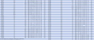
When choosing a diode, it is worth keeping in mind the fact: many cases can be essentially the same, but labeled differently. Some designations are completely devoid of numbers. Convenient to use search engines. The cross table of size correspondence shown is taken from the site selixgroup.spb.ru.
SMD diodes are often available in SOD123 package. If one end has a stripe of some color or embossing, then this is the cathode (the place where negative polarity needs to be applied to open the pn junction). If only the case has inscriptions, then this is the designation of the case. If there is more than one line, the one characterizing the shell is larger.
Item type and manufacturer
It is clear that the type of case is a secondary thing for the designer. Some heat will dissipate through the surface of the element. It is from this point of view that the diode should be considered. Other important characteristics are:
- Operating and reverse voltage.
- Maximum permissible current through the pn junction.
- Power dissipation, etc.
These parameters for semiconductor diodes are indicated in reference books. Labeling helps you find what you need among mountains of waste paper. In the case of an SMD element, the situation is much more complicated. There is no unified notation system. And at the same time it is easier - the parameters from one diode to another do not change too much. The power dissipation and operating voltage differ by and large. Each SMD element is marked with a sequence of 8 letters and numbers, and some of the acquaintances may not be used at all. This is the case with industry veterans, giants of the electronics industry:
- Motorola (2).
- Texas Instruments.
- Now converted and partially sold to Siemens (2).
- Maxim Integrated Product.
The mentioned manufacturers are sometimes marked with two letters MO, TI, SI, MX. In addition, a couple of letters address:
- AD – Analog Devices;
- HP – Hewlett-Packard;
- NS – National Semiconductors;
- PC, PS – Philips Components, Semiconductors, respectively;
- SE – Seiko Instruments.
Of course, the appearance of the case does not always make it possible to determine the manufacturer, then you need to immediately type the alphanumeric sequence into a search engine. Other examples have been noticed: the NXP diode assembly in the SOD123W package does not carry any information other than the line indicated above. The manufacturer considers the information provided sufficient. Because SOD itself stands for small outline diode. We’ll find more on the company’s official website (nxp.com/documents/outline_drawing/SOD123W.pdf).
Printing space is limited, which explains these simplifications. The manufacturer tries to make the marking process as minimal as possible. Laser or screen printing is often used. This will allow you to fit 8 characters in an area of only 4 square millimeters (Kashkarov A.P. “Marking of radio elements”). In addition to those indicated for diodes, the following types of housings are used:
- Cylindrical glass MELF (Mini MELF).
- SMA, SMB, SMC.
- MB-S.
To top it off, the same alphanumeric code sometimes corresponds to different elements. In this case, you will have to analyze the electrical circuit. Depending on the purpose of the diode, operating current, voltage, and some other parameters are assumed. According to the catalogs, it is recommended to try to determine the manufacturer, since the parameters have an insignificant scatter, making it difficult to correctly identify the product.
other information
In addition to those indicated at times, other information is provided. Batch number, release date. Such measures are taken to make it possible to track new product modifications. The design department issues corrective documentation with a number and date. And if the assembly shop needs to take a feature into account when working on the changes made, the craftsmen should read the markings.
If you assemble the equipment according to new drawings (electrical diagrams), using old parts, the result will not be what was expected. Simply put, the product will fail, it is gratifying if this is a reversible process. Nothing will burn. But even in this case, the shop manager will probably get hit in the head; the product will have to be remade in terms of the unaccounted factor.
Designations for the operation of an electrical circuit element
Schematic designation of a zener diode
Since the zener diode is a special diode, its designation is no different from them. Schematically, smd is designated as follows:
A zener diode, like a diode, has a cathode and anode part. Because of this, there is direct and reverse inclusion of this element.
At first glance, the inclusion of such a diode is incorrect, because it should be connected “the other way around”. In a situation where reverse voltage is applied to the SMD, the phenomenon of “breakdown” is observed. As a result, the voltage between its terminals remains unchanged. Therefore, it must be connected in series to a resistor in order to limit the current passing through it, which will ensure that the “excess” voltage from the rectifier drops.
Note! Each diode designed to stabilize voltage has its own “breakdown” (stabilization) voltage and also has its own operating current.
Due to the fact that each zener diode has such characteristics, it is possible to calculate the value of the resistor that will be connected in series with it. For imported zener diodes, their stabilization voltage is presented in the form of markings on the body (glass or not). The designation of such an smd diode always begins with BZY... or BZX..., and their breakdown (stabilization) voltage is marked V. For example, the designation 3V9 stands for 3.9 volts.
Note! The minimum voltage for stabilization of such elements is 2 V.
Semiconductor diodes
Perhaps the name of the section is somewhat trivial; it was necessary to distinguish ordinary diodes from obsolete electronic tubes and the most modern SMD modifications. Ordinary semiconductor diodes are the simplest disaster for a radio amateur. The side of the cylindrical body with a disk base and legs contains an easily visible inscription painted with paint.
Semiconductor resistors. Can you tell the difference with the naked eye?
The color of the case does not matter; the size indirectly indicates the power dissipation. Powerful diodes often have a thread for the radiator mounting nut. The result of calculating the thermal regime shows the lack of the body’s own capabilities; the cooling system is supplemented by an external element. Today, power consumption is falling, reducing the linear dimensions of device housings. This allowed the use of glass. The new housing material is cheaper, more durable, and safer.
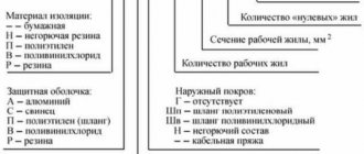
- The first place is occupied by a letter or number that briefly characterizes the material of the element:
- G (1) – germanium compounds.
- K (2) – silicon compounds.
- A (3) – gallium arsenide.
- And (4) – indium compounds.
- The second letter in our case is D. Rectifier or pulse diode.
- The third place was chosen by the figure characterizing the applicability of the diode:
- Low frequency, current below 0.3 A.
- Low frequency, current 0.3 - 10 A.
- Not used.
- Pulse, recovery time over 500 ns.
- Pulse, recovery time 150 - 500 ns.
- The same, recovery time 30 - 150 ns.
- The same, recovery time 5 - 30 ns.
- The same, recovery time 1 - 5 ns.
- Pulsed, minority carrier lifetime below 1 ns.
- The development number is composed of two digits and may be absent altogether. Denominations below 10 are padded on the left with a zero. For example, 07.
- The group number is indicated by a letter and determines the differences in properties and parameters. The letter is often the key letter; it can indicate the operating voltage, forward current, and much more.
In addition to the markings, the reference books provide graphs that can be used to solve the problem of choosing the operating point of a radio element. Information about production technology, body material, and weight may be indicated. The information helps the equipment designer, but has no practical meaning for amateurs.
Imported designation systems differ from domestic ones and are well standardized. Therefore, using special tables it is quite easy to find suitable analogues.
Operating principle of stabilization diodes
Despite the fact that the SMD is similar to a diode, it is essentially a different element of the electrical circuit. Of course, it can serve as a rectifier, but is usually used to stabilize the voltage. This element is capable of maintaining a constant voltage in a DC circuit. This principle of operation is used in power supply of various radio equipment.
Zener diode and diode
Externally, SMD is very similar to a standard semiconductor. The similarity remains in the design features. But when designating such a radio element, unlike a diode, the letter G is placed on the diagram. If you do not delve into mathematical calculations and physical phenomena, then the operating principle of smd will be quite clear.
Note! When turning on such an SMD diode, you must observe reverse polarity. This means that the connection is made with the anode to the minus.
Passing through this element, a small voltage in the circuit provokes a strong current. As the reverse voltage increases, the current also increases, only in this case its growth will be observed weakly. When you reach the mark, it can be anything. It all depends on the type of device. When the mark is reached, a “breakdown” occurs. After the “breakdown” has occurred, a large reverse current begins to flow through the smd. It is at this moment that the operation of this element begins until its permissible limit is exceeded.
Diodes - characteristics, designation and marking of diodes
- current passing through the diode in the forward direction (direct current Ipr);
- current passing through the diode in the opposite direction (reverse current Irev);
- the highest permissible rectified CURRENT Ivypr.max;
- the highest permissible direct current Ipr.add.;
- direct voltage Unp;
- reverse voltage IOBR;
- highest permissible reverse voltage iobr.max
- capacitance CD between the diode terminals;
- dimensions and operating temperature range.
How to distinguish a stabilization diode from a conventional semiconductor
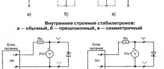
Very often people wonder how they can distinguish a zener diode from a standard semiconductor, because, as we found out earlier, both of these elements have almost identical symbols on the electrical circuit and can perform similar functions. The easiest way to distinguish a stabilization semiconductor from a regular one is to use a multimeter attachment circuit. With its help, you can not only distinguish both elements from each other, but also identify the stabilization voltage, which is characteristic of a given SMD (if it, of course, does not exceed 35V). The multimeter attachment circuit is a DC-DC converter, in which there is galvanic isolation between the input and output. This diagram looks like this:
Multimeter attachment circuit
In it, a generator with pulse-width modulation is implemented on a special microcircuit MC34063, and to create galvanic isolation between the measuring part of the circuit and the power source, the control voltage should be removed from the primary winding of the transformer. For this purpose there is a rectifier on VD2. In this case, the value for the output voltage or stabilization current is set by selecting resistor R3. A voltage of approximately 40V is released at capacitor C4. In this case, the tested SMD VDX and the stabilizer for current A2 will form a parametric stabilizer. The multimeter, which is connected to terminals X1 and X2, will measure the voltage at this zener diode. When connecting the cathode to the “-” and the anode to the “+” of the diode, as well as to the asymmetrical SMD of the multimeter, the latter will show a slight voltage. If you connect in reverse polarity (as in the diagram), then in a situation with a conventional semiconductor, the device will register a voltage of about 40V.
Note! For symmetrical SMD, the breakdown voltage will appear in the presence of any connection polarity.
Here the T1 transformer will be wound on a torus-shaped ferrite core with an outer diameter of 23 mm. Such winding 1 will contain 20 turns, and the second winding will contain 35 turns of PEV 0.43 wire. In this case, it is important to lay the turn to the turn when winding. It should be remembered that the primary winding goes on one part of the ring, and the second on the other. When setting up the device, connect a resistor instead of smd VDX. This resistor should have a value of 10 kOhm. And resistance R3 needs to be selected in order to achieve a voltage of 40V on capacitor C4. This is how you can find out whether you have a zener diode or a regular diode.
A little more about the module and how it works
This is a semiconductor diode that has the property of producing a certain voltage value regardless of the current supplied to it. This statement is not completely true for absolutely all options, because different models have different characteristics. If you apply a very strong current to an SMD module (or any other type) that is not designed for this purpose, it will simply burn out. Therefore, the connection is made after installing a current-limiting resistor as a fuse, the value of the output current of which is equal to the maximum possible value of the input current to the stabilizer.
It is very similar to an ordinary semiconductor diode, but has a distinctive feature - its connection is done in reverse. That is, the minus from the power source is supplied to the anode of the zener diode, and the plus to the cathode. Thus, a reverse branch effect is created, which provides its properties.
A similar module is a stabistor - it is connected directly, without a fuse. It is used in cases where the parameters of the input electricity are precisely known and do not fluctuate, and the output also produces an exact value.
Details about the color coding of the stabilizing diode
Any diode (zener diode, etc.) contains a special marking on its case, which reflects what material was used to manufacture each specific semiconductor. Such marking may look like this:
In addition, the marking reflects the electrical properties and purpose of the device. Usually a number is responsible for this. The letter, in turn, reflects the corresponding type of device. In addition, the marking contains the date of manufacture and the symbol of the product. Integral type SMDs often contain full markings. In such a situation, there is a conditional code on the product body that indicates the type of microcircuit. An example of decoding the code markings for microcircuits applied to the housing is shown in the figure:
Marking of zener diodes
Markings are applied to the zener diode housing in the form of numbers and letters (or letters). There are fundamentally two different types of markings. The zener diode in a glass case has the usual markings for us, directly indicating the rated stabilization voltage. The numbers can be separated by the letter V, which acts as a decimal point. For example, 5V1 means 5.1 V.
A less clear way of marking consists of four numbers and a letter at the end. If you are not an experienced radio amateur, then you can’t do without a datasheet. For example, let's decipher the parameters of the reference diode of the 1N5349B series. We are most interested in the first column, which shows the rated voltage of 12 V. The second column is the rated current value - 100 mA.
The cathode of a zener diode of any type is indicated by a black or blue ring, which is applied to the body from the side of the corresponding terminal.