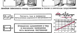
Ohm's law for a section of a circuit is one of the fundamentals of electrical engineering. This law indicates the relationship between current, voltage and resistance.
Ohm's Law itself for a section of a circuit reads like this:
The current strength in a conductor (section of an electrical circuit) is directly proportional to the applied voltage and inversely proportional to the resistance of the conductor (section of an electrical circuit)
[G.S. Om, 1826]
From this definition, Georg Ohm derived the following formula:
I = U/R or U = R*I
The formula resulting from Ohm's law is also known colloquially as the URI formula . This name comes from the sequence of letters in the formula:
U = R*I
- R—conductor resistance (Ohm);
- I is the current strength in the conductor (Ampere);
- U is the voltage applied to the conductor (Volts).
Basic Concepts
Voltmeter
Voltage drop is the value reflected in the change in potential in different parts of the conductor. The current flowing from the source towards the load changes its parameters due to the resistance of the wires, but its direction remains unchanged. You can measure the voltage using a voltmeter:
- two devices at the beginning and end of the line;
- alternate measurements in several places;
- a voltmeter connected in parallel to the cable.
The simplest circuit is a power source, conductor, load. An example would be an incandescent lamp plugged into a 220 V socket. If you measure the voltage on the lamp with a device, it will be slightly lower. The drop occurred in the lamp resistance.
The voltage or voltage drop across a section of a circuit can be calculated using Ohm's law using the formula U = IR, where:
- U – electrical voltage (volts);
- I – current strength in the conductor (ampere);
- R – resistance of the circuit or its elements (ohms).
Knowing any two quantities, you can calculate the third. In this case, it is necessary to take into account the type of current - alternating or direct. If there are several parallel connected resistances in the circuit, the calculation becomes somewhat more complicated.
Basic concepts and laws of electrical circuits. Question answer.
Question 1. Define the concept of “electrical circuit”, “electrical circuit”, “node”, “branch”, “current sources”, “EMF source”. Answer. An electrical circuit is a collection of devices designed to carry electric current. The devices that form an electrical circuit are sources of electromagnetic energy - generators, consumers of electromagnetic energy - receivers and energy transmission systems. An electrical diagram is a graphical representation of an electrical circuit. The diagram shows the sequence of connecting the two-terminal networks that make up the electrical circuit. A branch is the entire section of an electrical circuit along which the current has the same value. A node is a junction of three or more branches. An electrical circuit node in the diagram is marked with a bold dot. A current source is a generator that creates a current independent of the load resistance. The voltage source (EMF) is a generator with internal resistance equal to zero.
Question 2. What is meant by current-voltage characteristic? Answer. A graph depicting the dependence of the voltage on a two-terminal network on the current through a two-terminal network is called the current-voltage characteristic (CVC) of this two-terminal network.
Rice. 1. Current-voltage characteristics. Curve a represents the current-voltage characteristic of such a two-terminal network, the resistance of which does not depend on either the current through the two-terminal network or the voltage across it; its current-voltage characteristic will be a straight line passing through zero; such two-terminal networks are called linear. Curve b represents the current-voltage characteristic of such a two-terminal network, the resistance of which increases with increasing current. An example of such a two-terminal circuit is an incandescent light bulb with a tungsten filament. The resistivity of tungsten increases with increasing temperature, and therefore with increasing current through the filament. Curve b depicts the current-voltage characteristic of a gas-discharge device. According to this current-voltage characteristic, the resistance of the device should decrease with increasing current. Characteristics b, e, and d belong to resistances that do not obey Ohm's law. An incandescent lamp and a gas-discharge device are nonlinear resistances.
Question 3. Draw the current-voltage characteristic of a real source, EMF source, current source, linear resistance. Answer.
Rice. 2. Current-voltage characteristic: a - real EMF source; b - ideal EMF source; c - ideal current source; g - linear resistance.
Question 4. Formulate Ohm’s law for the section of the circuit with EMF, Kirchhoff’s first and second laws. Write down in letter form how many equations should be formed according to Kirchhoff's first and second laws? Answer. Ohm's law: with a constant resistance of a conductor, the voltage across it is proportional to the current in the conductor. The mathematical expression of this Ohm's law is:
. Kirchhoff's first law. The first law determines the balance of currents in the nodes of an electrical circuit: the algebraic sum of currents in the branches connected by a common node of the electrical circuit is equal to zero; or the sum of currents leaving a node in an electrical circuit is equal to the sum of currents coming to this node. We will consider outgoing currents to be positive and incoming currents to be negative. The mathematical expression of Kirchhoff's first law has the form: or , where are the numbers of branches connected by a given node. Kirchhoff's second law. Kirchhoff's second law establishes the balance of voltages in the circuits of an electrical circuit: in any circuit of an electrical circuit, the algebraic sum of the voltages on the individual elements of the circuit is zero. The mathematical expression of the law or the second Kirchhoff equation has the form: or , where are the indices of all active and passive elements of the circuit, including the internal resistance of generators; - voltages on these elements. The second Kirchhoff equation can be written as follows: , where is the number of passive elements; — number of voltage sources. This equation is read as follows: in any circuit of an electrical circuit, the algebraic sum of the voltage drops is equal to the algebraic sum of the emf acting in this circuit. Formulas and examples of solving TOE problems are here.
Question 5: What is the difference between voltage and voltage drop? Answer. Voltage (for a generator) is the potential difference between the terminals of a running generator. The voltage drop (in the generator) is the difference between the emf. and the voltage at its terminals, created by the current in the resistances of the current-carrying elements of the generator itself. Voltage (in a line) is the potential difference between the wires. Voltage drop (in a line) is the potential difference along the wires that occurs when there is current in the line due to the resistance of the line wires themselves. Voltage and voltage drop (at the receiver) are the same potential difference between its terminals.
Question 6. What manifestations of a magnetic field do you know? Answer. The energy of the magnetic field is stored in the inductance.
Question 7. Define L. Answer. Proportionality factor equal to
is called the static inductance of the coil. Coil flux linkage: - the product of the number of turns of the coil and the value of the magnetic flux. The dynamic inductance of the coil is determined by the formula: LД=. If the coil is linear, then the dynamic inductance of the coil does not differ from its static inductance and is simply called inductance.
Question 8. What manifestations of the electric field do you know? Answer. The energy of the electric field accumulates in the container.
Question 9. Define C. Answer. Capacitance (C) between two conductors is the absolute value of the ratio of the electric charge of one conductor to the potential difference between the conductors, provided that these conductors have charges of equal but opposite sign. The unit of capacitance is the farad (F). Capacitance is an ideal capacitor that has neither inductance nor resistance.
Question 10. Formulate the Joule-Lenz law. Answer. Joule-Lenz law: the work done by current i in resistance r during time t is determined by the expression:
or , where u is the voltage across resistance r, equal to .
Source: Nikolsky O.K., Kulikova L.V., Semichevsky P.I., Germanenko V.S. Theoretical foundations of electrical engineering: In 2 volumes. Textbook for universities.
Source
In ordinary human life, the words “loss” and “fall” are used to denote the fact of a decrease in certain achievements, but they mean different amounts.
In this case, “losses” means the loss of a part, damage, or a decrease in the amount of a previously achieved level. Losses are undesirable, but they can be tolerated.
The word “fall” refers to more serious damage associated with complete deprivation of rights. Thus, even occasional losses (say, of a wallet) over time can lead to a decline (for example, of the standard of material life).
In this regard, let's consider this issue in relation to the voltage of the electrical network.
How losses and voltage drop occur
Electricity is transmitted over long distances via overhead lines from one substation to another.
Overhead line wires are designed to transmit permissible power and are made of metal cores of a certain material and cross-section. They create an active load with a resistance value of R and a reactive load with a resistance value of X.
On the receiving side there is a transformer that converts electricity. Its windings have an active and pronounced inductive reactance XL. The secondary side of the transformer reduces the voltage and transmits it further to consumers, the load of which is expressed by the value Z and is active, capacitive and inductive in nature. It also affects the electrical parameters of the network.
The voltage applied to the wires of the overhead line support closest to the substation transmitting electricity overcomes the reactive and active resistance of the circuit in each phase and creates a current in it, the vector of which deviates from the vector of the applied voltage by an angle φ.
The nature of the voltage distribution and current flow along the line for a symmetrical load mode is shown in the picture.
Since each phase of the line feeds a different number of consumers, which are also randomly disconnected or connected to operation, it is technically very difficult to perfectly balance the phase load. There is always an unbalance in it, which is determined by the vector addition of the phase currents and is written as 3I0. In most calculations it is simply ignored.
The energy expended by the transmitting substation is partially spent on overcoming the line resistance and reaches the receiving side with minor changes. This fraction is characterized by loss and voltage drop, the vector of which decreases slightly in amplitude and shifts in angle in each phase.
How are losses and voltage drop calculated?
To understand the processes occurring during the transmission of electricity, a vector form of representing the main characteristics is convenient. Various mathematical calculation methods are also based on this method.
To simplify calculations in a three-phase system, it is represented by three single-phase equivalent circuits. This method works well with a symmetrical load and allows you to analyze processes when it is violated.
In the above diagrams, the active R and reactive X resistance of each line wire are connected in series to the complex load resistance Zн, characterized by the angle φ.
Next, the loss and voltage drop in one phase are calculated. To do this, you need to specify data. For this purpose, a substation is selected that receives energy, at which the permissible load must already be determined.
The voltage value of each high-voltage system is already specified in reference books, and the resistance of the wires is determined by their length, cross-section, material and network configuration. The maximum current in the circuit is specified and limited by the properties of the conductors.
Therefore, to start the calculations we have: U2, R, X, Z, I, φ.
We take one phase, for example, “A” and plot for it on the complex plane the vectors U2 and I, shifted by an angle φ, as shown in Figure 1. The potential difference across the active resistance of the wire coincides in direction with the current, and in magnitude is determined by the expression I ∙R. This vector is set aside from the end of U2 (Fig. 2).
The potential difference across the reactance of the wire differs from the direction of the current by an angle φ1 and is calculated by the product I∙X. We set it aside from the vector I∙R (Fig. 3).
Reminders: the positive direction of rotation of vectors on the complex plane is taken to be the movement opposite to the clockwise direction. The current passing through an inductive load lags behind the applied voltage.
Figure 4 shows the drawing of the vectors of the potential difference at the total resistance of the wire I∙Z and the voltage at the input to the circuit U1.
Now you can compare the vectors at the input to the equivalent circuit and the load. To do this, we position the resulting diagram horizontally (Fig. 5) and from the origin we draw an arc with module radius U1 until it intersects with the direction of vector U2 (Fig. 6).
Figure 7 shows an enlargement of the triangle for clarity and the drawing of auxiliary lines and the designation of characteristic intersection points with letters.
The bottom of the picture shows that the resulting vector ac is called the voltage drop, and ab is called losses. They differ in size and direction. If we return to the original scale, we will see that ac was obtained as a result of geometric subtraction of vectors (U2 from U1), and ab was obtained as a result of arithmetic subtraction. This process is shown in the picture below (Fig. 8).
Deriving formulas for calculating voltage loss
Now let's go back to Figure 7 and notice that the segment bd is very small. For this reason, it is neglected in calculations, and voltage losses are calculated based on the length of the segment ad. It consists of two segments ae and ed.
Since ae=I∙R∙cosφ, and ed=I∙x∙sinφ, the voltage loss for one phase can be calculated using the formula:
The values of active P and reactive power Q can be taken from the readings of line electricity meters.
Thus, voltage losses in an electrical circuit depend on:
active and reactance circuit resistance;
components of applied power;
the magnitude of the applied voltage.
Deriving formulas for calculating the transverse component of the voltage drop
Let's return to Figure 7. The vector quantity ac can be represented by the hypotenuse of a right triangle acd. We have already calculated the leg ad. Let us determine the transverse component cd.
The figure shows that cd=cf-df.
Using the derived patterns, we will carry out small mathematical transformations and obtain the transverse component of the voltage drop.
Determining the formula for calculating the voltage U1 at the beginning of the power line
Knowing the magnitude of the voltage at the end of the line U2, the losses ∆Uл and the transverse component of the drop δU, we can calculate the magnitude of the vector U1 using the Pythagorean theorem. In expanded form it looks like this:
Calculation of voltage losses is carried out by engineers at the stage of creating an electrical circuit design for the optimal selection of the network configuration and its constituent elements.
During the operation of electrical installations, if necessary, simultaneous measurements of voltage vectors at the ends of lines can be periodically carried out and the results obtained can be compared using simple calculations. This method is relevant for devices that are subject to increased requirements due to the need for high precision operation.
Voltage losses in secondary circuits
An example is the secondary circuits of measuring voltage transformers, which sometimes reach several hundred meters in length and are transmitted by a special power cable of increased cross-section.
The electrical characteristics of such a cable are subject to increased requirements for the quality of voltage transmission.
Modern protection of electrical facilities requires the operation of measuring systems with high metrological indicators and an accuracy class of 0.5 or even 0.2. Therefore, the voltage losses supplied to them must be monitored and taken into account. Otherwise, the error they introduce into the operation of the equipment can significantly affect all operational characteristics.
Voltage losses inside long cable lines
The design feature of a long cable is that it has capacitance due to the fairly close arrangement of the conductive cores and a thin layer of insulation between them. It additionally deflects the current vector passing through the cable and changes its magnitude.
The effect of reducing the voltage on the capacitance must be taken into account in the calculation for changing the value of I∙z. Otherwise, the technology described above remains unchanged.
The article provides examples of losses and voltage drops on overhead power lines and cables. However, they occur in all electrical consumers, including electric motors, transformers, inductors, capacitor units and other devices.
The amount of voltage loss for each type of electrical equipment is legally regulated in relation to operating conditions, and the principle of their determination in all electrical circuits is the same.
If you liked this article, share a link to it on social networks. This will greatly help the development of our site!
Subscribe to our channel on Telegram!
Just follow the link and connect to the channel.
Don't miss updates, subscribe to our social networks:
Source
Result of undervoltage
A common phenomenon is when the input voltage is detected below the established norm. Subsidence along the length of the cable occurs due to the passage of high current, which causes an increase in resistance. Losses also increase on long lines, which is typical for rural areas.
According to regulations, losses from the transformer to the most remote area should be no more than 9%. The result of deviation of parameters from the norm may be as follows:
- failure of energy-dependent installations and equipment, lighting devices;
- failure of electrical appliances at low input voltages;
- reduction in torque when starting an electric motor or compressor unit;
- starting current leads to overheating and shutdown of the engine;
- uneven current load at the beginning of the line and at the remote end;
- lighting fixtures operate at full intensity;
- losses of electricity, underutilization of current power.
The characteristics and operating parameters of electrical appliances are changing. For example, due to low power, the time for heating water by a boiler increases. A decrease in voltage leads to failures in the electronics.
In operating mode, voltage loss in the cable can be up to 5%. This value is acceptable for energy industry networks, since high power currents are delivered over long distances. Such lines are subject to increased requirements. Therefore, in case of household losses, attention should be paid to secondary energy distribution networks.
Checking the cable for voltage loss
Everyone knows that the flow of electric current through a wire or cable with a certain resistance is always associated with a loss of voltage in this conductor.
According to the rules of the River Register, the total loss of electrical voltage in the main distribution board to all consumers should not exceed the following values:
- for lighting and signaling at a voltage of more than 50 volts - 5%;
- for lighting and signaling at a voltage of 50 volts - 10%;
- for power consumption, heating and heating systems, regardless of electrical voltage – 7%;
- for power consumption with short-term and intermittent operating modes, regardless of electrical voltage – 10%;
- when starting engines – 25%;
- when powering a radio switchboard or other radio equipment or when charging batteries – 5%;
- when supplying electricity to generators and distribution boards - 1%.
You may be interested in this: How to find out amperage
Based on this, various types of cables capable of supporting such voltage loss are selected.
Example of a calculator for automating calculations
Causes of voltage drop
Phase imbalance in a three-phase circuit
First of all, you need to figure out whether it is the fault of the electricity supplier or the consumer. Network problems arise for the following reasons:
- deterioration of power lines;
- insufficient power of transformers;
- power imbalance or phase imbalance.
These problems are related to the supplier and cannot be resolved independently. To understand whether high-voltage lines are working correctly or not, you will have to call energy sales representatives. They will take measurements and draw up a conclusion.
You can make sure that the fault of the fall is not related to the supplier yourself. First of all, you should find out from your neighbors if they have similar problems. A multimeter is suitable for measuring voltage at home. Its cost is up to 1000 rubles. If the device at the entrance to the apartment shows normal voltage, the reason must be looked for in the home network.
The voltage may drop due to the long length of the wiring. When the length of the network exceeds 100 meters and the cross-section of the conductors is 16 mm, the oscillations will become regular. To correct the situation, you will have to change the wiring.
Weak contacts are additional resistance to current. It reaches devices in insufficient quantities. In addition, faulty contacts can cause a short circuit and lead to a fire. To normalize the performance, you need to replace the faulty section of the circuit and burnt contacts.
The culprit may be an incorrect connection of the wires running from the power lines to the house. Sometimes, contrary to safety requirements, copper wires are connected to aluminum or copper conductors are connected by twisting instead of terminals. The terminals and clamps are made of low-quality materials or their expiration date has expired.
Perhaps the fault lies in the input device itself. In this case, it should be replaced.
Real voltage measurement examples
The simplest example of measuring voltage at home is a AA battery. In it you need to attach the black probe to the “–” terminal and the red one to the “+” terminal, set the switch position to 2 V DC voltage.
Rice. 4. Example of measuring voltage on a battery
If the readings for a 1.5 V battery are in the range from 1.6 to 1.2 V, then such a power source is considered suitable for all equipment; if the values reduce to 1 - 0.7 V, pulsed devices will be started from the battery, for example, a watch. If the voltmeter shows 0.6 V or less, the discharge has reached a critical value.
When measuring the potential difference in a household network, you should touch the contacts of the socket with the probes. Since the insulated part of the probe has a restrictive ring behind which there is a long rod, you can safely reach into the outlet without the risk of touching live parts. Deviations from the nominal value by 10% are considered acceptable, that is, from 198 to 142 V.
You can also measure the potential difference at the output of a car battery or at another element of the electrical wiring circuit. To do this, the black probe of the multimeter is installed on the “–” terminal of the battery, and the red one on the “+” terminal.
If the battery is charged, then the voltmeter readings should be in the range from 12 to 14 V, but there are models with a large spread. This measurement allows you to diagnose various causes of problems.
How to calculate losses
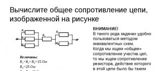
Linear relationship between voltage and current
When calculating an electrical line, voltage deviations should not exceed regulated standards. Permissible fluctuations for household single-phase networks are 209–231V; for a three-phase network, the voltage can vary from 361 to 399 V.
Fluctuations in current and power consumption lead to changes in voltage in the conductors near the consumer. Therefore, when drawing up a wiring diagram, it is necessary to take into account the allowable losses.
In a single-phase network there are two wires, so the voltage drop can be found using the following formula: U=I*R, in turn, R=(r*2i)/S.
- where r is the resistivity, which is equal to the resistance of a wire with a cross-section of 1 mm2 and a length of 1 m;
- i – designated as the length of the conductor;
- S – cable section.
AutoCad program for calculating voltage drop
In a three-phase network, the powers on the phase wires compensate each other, and the length of the neutral conductor is not taken into account, since no current flows through it. If the load across the phases is uneven, the calculation is performed as for a single-phase network. For long lines, capacitive and inductive reactance are additionally taken into account.
The fall can be calculated using an online calculator, and there are also special tables. They show the permissible current loads for different types of cables. When calculating the cable cross-section, the following data must be taken into account:
- conductor material;
- hidden or open laying of the line;
- current load;
- environmental conditions.
When current flows through a cable, wire or bus, it heats up. This process changes the physical properties of the conductors. The insulation melts, the contacts overheat, and the wire burns out. The reliability and uninterrupted operation of the electrical network depends on the correct selection of cable.
How to calculate resistance for voltage drop: resistor drop formula
A resistor is one of the most common elements in an electrical circuit. With its help, the current is limited and the voltage is changed. When designing circuits, you may often need to calculate the resistance to reduce the voltage. This is relevant when constructing dividers for digital devices or power supplies, so every radio amateur should be able to perform such calculations.
A resistor is an element used in an electrical circuit and does not require a power source for its operation. It is designed to transform current into voltage and vice versa. In addition, it can convert electrical energy into thermal energy and limit the amount of current. But before calculating the voltage drop across a resistor, it is advisable to understand the essence of this process.
A resistor is a very common element characterized by a number of parameters. The main ones are:
- resistance;
- the amount of energy dissipated;
- operating voltage;
- power;
- resistance to environmental influences;
- parasitic component.
A passive electrical element is indicated in the diagram as a rectangle with two terminals from the middle of its sides. In the center of the figure, power can be indicated in Roman numerals or dashes. For example, a vertical stripe indicates the element's withstand power of 1 W. The crossed out rectangle in the notation in the diagram indicates that such a resistor is variable.
Resistors can be produced with constant and variable resistance. A type of the latter are tuning elements. The only difference between them and variables is the way they are set to the desired value.
On diagrams and in technical literature, the device is designated by the Latin letter R, next to which the serial number and its denomination are indicated in accordance with the International System of Units (SI). For example, R12 5 kOhm is a five kilo-ohm resistor located in the circuit under number 12.
When manufacturing an element, a resistive layer is used, which can be film or volumetric. It is applied to a dielectric base and covered with a protective film on top.
Resistance value
Resistance is a fundamental quantity in electrical processes. Its meaning is invariably related to current and voltage. Their general dependence is described using Ohm's law: the current strength arising in a section of the circuit is directly proportional to the potential difference between the extreme points of this section and inversely proportional to its resistance. From this law the resistance is found using the following formula:
R = U / I, where:
- R is the resistance in the circuit section, Ohm.
- I is the current strength passing through this section, A.
- U is the potential difference at the nodes of a part of the circuit, V.
In fact, the resistance of an element is determined by its physical structure and is caused by the vibrations of atoms in the crystal lattice. Therefore, all materials are classified as conductors, semiconductors and dielectrics depending on their ability to conduct electricity.
Current is the directed movement of charge carriers. For it to occur, the substance must have free electrons. If an electric field is applied to such a physical body, then the charges it moves will begin to collide with inhomogeneities in the structure. These defects are formed due to various impurities, violation of lattice periodicity, and thermal fluctuations. By hitting them, the electron expends energy, which is converted into heat. As a result, the charge loses momentum, and the magnitude of the potential difference decreases.
But Ohm's law cannot be applied to all substances. In electrolytes, dielectrics and semiconductors, a linear relationship between the three quantities is not always observed. The resistance of such substances depends on the physical parameters of the conductor, namely its length and cross-sectional area, and it is sensitive to temperature changes.
This dependence is described using the formula R = p * l / S. That is, the resistance is directly proportional to the length and inversely proportional to the area of the conductor. The value p is called resistivity and is determined by the type of material. Its meaning is taken from the reference book.
Resistor impedance
Ohm's law applies to an ideal resistor that has no parasitic resistance. The total resistance (impedance) is determined based on the equivalent circuit. Accurate calculation of resistance to reduce voltage must be carried out using other formulas. The equivalent circuit of a resistor, in addition to active impedance, also contains capacitive and inductive reactance.
The first leads to a slow accumulation of charge, which dissipates when the direction of the current changes. The larger the parasitic capacitance, the longer it takes to charge. Accordingly, the faster the current changes its direction, the lower its capacitance. The second is characterized by a magnetic field, whose appearance prevents the current from changing direction, therefore, the faster the current changes its movement, the greater the inductive reactance becomes.
Impedance is calculated using the formula: I = U/Z, where Z = (R2+(Xc-Xl)2)½. Where:
- R is the active value, R = p*l/s.
- Xc is a capacitive value, Xc = 1/w*C.
- Xl is an inductive quantity, Xl = w*C.
- w is the cyclic frequency, w = 2πƒ.
Knowing the total resistance of the resistor, you can more accurately calculate the voltage drop in it. But to measure parasitic components you will need to use highly specialized instruments. In conventional calculations, resistance is calculated taking into account only its active value, and parasitic values are taken as negligible.
Parallel connection
Electrical circuits use both parallel and series connections in sections of the circuit. The first is a circuit in which each element is connected to the other by both contacts, but there is no direct electrical connection between its own terminals. That is, there are two points (electrical nodes) to which several resistors are connected.
With this switching on, the current passing through the node begins to split, and a different value will flow through each element. The amount of current in each element will be directly proportional to the resistance of the resistor, so the total conductivity in this section will increase, and its impedance will decrease.
The formula with which you can calculate the total conductivity looks like this: G = 1/ Rtot = 1/ R1 + 1/ R2 +…+ 1/ Rn, where n denotes the serial number of the resistor in the circuit.
Transforming this formula, you get an expression of the form: R total = 1/G = (R1*R2*…* Rn) / (R1*R2 + R2*Rn +…+ R1*Rn. Having analyzed it, we can conclude that with parallel connection, the impedance will always be less than the smallest value of an individual resistor.
With such a connection, the voltage between the nodes is simultaneously the total potential difference for the entire section and at each individual resistor. Therefore, if you calculate the voltage drop on one device, then it will be the same on any parallel-connected element: U total = U 1 = U 2 =...= U n.
But the electric current passing through a separate element, based on Ohm’s law, will be equal to: I Rn = U Rn / R n.
Serial connection
This is the name for combining two or more resistors into one section of a circuit, in which their connection to each other occurs only at one point. Impedance when connected in series is defined as the sum of the resistances of each individual element: Rtotal = R1+R2+…+Rn.
Consequently, the current flowing through such a chain will become less and less after passing through a series-connected resistor. The more elements there are in the chain, the more difficult it will be for him to pass them all. Thus, its overall value is determined as Itotal = U / (R1+R2+…+Rn).
Therefore, it can be argued that in a series connection there is only one path for current to flow. The greater the number of resistors in the line, the less current will be in this section.
We recommend reading: How to check a battery with a multimeter: for performance
The drop in potential difference with this type of connection on each element will have its own meaning. It is determined by the formula URn = IRn*Rn, and the greater the impedance of the element, the more energy it will begin to release.
Voltage divider calculation
A resistive voltage divider represents a basic circuit for reducing voltage. It can consist of two or more elements. The simplest divider can be represented as two sections of the chain, which are called shoulders. One of them, which is located between the positive and zero potential points, is the upper one, and the other, between the negative and minus ones, is the lower one.
This circuit is used to reduce voltage in both constant and variable circuits. The essence of the process is as follows.
- The resistive circuit is supplied with voltage U from the power source.
- Current begins to flow through the resistors of the series section of the circuit formed by resistors R1 and R2.
- As a result, a certain amount of energy is released at each of them, i.e., a voltage drop occurs.
The sum of the voltages across the entire line span is equal to the potential difference of the power source. In accordance with the formula: U = I*R, the voltage drop is directly proportional to the current strength and resistance value. Considering that the current flowing through the resistors is the same, the formulas U1 = I*R1 and U2= I*R2 will be valid.
Then the total voltage drop in the section will be equal to U = I * (R1+ R2). Based on this, you can find the current strength: I = U / (R1+ R2). Using these two expressions, the final formulas for calculating the voltage drop across each element can be obtained:
- U1 = R1*U/(R1+R2);
- U2 = R2*U/(R1+R2).
The practical use of such a divider is very common due to the ease of implementing voltage reduction. For example, let the power supply supply 12 V, and the load needs to be supplied with 6 V, while its resistance is 10 kOhm. To solve this problem, it is recommended to use resistors whose resistance is ten times less than the load value, therefore, taking R 1 = 1 kOhm and substituting all known values into the voltage formula on the resistor, it turns out that 6 = R 2 * 12 (1000+ R 2 ) hence R 2 = 1 kOhm.
Now, knowing all the values, you can check the accuracy of the calculation. The potential difference drop across the first element is calculated as U 1 = 1000*12/(1000+1000) = 6 V, and the total voltage is Utot = U 1+ U 2 = 12 V, which corresponds to the value of the power source.
It should be noted that the use of pull-down resistors is only used for low-power loads, since some of the energy is converted into heat and the coefficient of performance (COP) is very low.
How to Reduce Voltage Drop and Cable Loss
You can reduce the amount of losses by reducing the resistance throughout the electrical network. Savings come from the method of re-grounding the zero on each power line support.
The cost of power supply with a long-distance line selected based on the permissible voltage drop is higher than the choice made based on cable heating. There is still an opportunity to reduce these costs.
- Strengthen the initial potential of the supply cable by connecting it to a separate transformer.
- You can achieve constant voltage levels in the network by installing a stabilizer near the load.
- Connection of consumers with low loads of 12–36 V is carried out through a transformer or power supply.
The longer the power line cable, the greater the resistance that occurs when current passes through it. Obviously, the voltage loss is also higher. They can be reduced by combining methods with each other.
- Reduce costs by increasing the cross-section of the power cable. But this method will require large financial investments.
- When developing power supply lines, you should choose the shortest possible path, since a straight line is always shorter than a broken line.
- As the temperature decreases, the resistance of metals decreases. Ventilated cable trays and other designs reduce line losses.
- Load reduction is possible if there are many power sources and consumers.
Savings come from proper maintenance and prevention of electrical networks - checking the density and strength of contacts, using reliable terminal blocks.
The issue of energy conservation must be approached with full responsibility. The problem of voltage loss can damage expensive devices and tools. Do not neglect safety measures; they will level out power surges and protect household appliances and equipment in the enterprise.