Purchase
You can buy a wire with the most favorable conditions by contacting our company. We work with trusted manufacturers and do not use the services of intermediaries, which allows us to reduce the cost of cable and wire products to a minimum. Placing an order is done in the fastest and most convenient way - through the website or by email. After receiving your questionnaire, we immediately begin to formulate the terms of purchase.
We work with individuals and legal entities, engaged in wholesale and retail trade. Complete with the product, the customer receives a certificate of conformity and a quality certificate. If necessary, our consultants will answer all your questions. You can buy products from the assortment available in the warehouse or from the manufacturer to order. The price of SIP-3 wire depends on the delivery conditions and order volume. For regular customers, we have provided a system of discounts and special offers.
Advantages and disadvantages of using SIP
These wires allow:
- ensure the required electrical safety class;
- increase network reliability during operation;
- reduce the cost of maintaining the electrical network (up to 80%);
- reduce installation time and reduce labor costs;
- place electrical lines on the walls of buildings;
- reduce losses during electricity transmission (due to low resistance);
- connect objects without disconnecting the main supply line;
- lay and connect lines on your own.
Disadvantages of SIP:
- cost 20-25% more than conventional wires without insulation;
- many energy suppliers are not ready to use SIP (outdated equipment and no tools for installation);
- Only overhead power lines can be laid.
Application
The cable is used when installing overhead power lines. The cable transmits and distributes electrical energy between consumers; the alternating current parameters in the network must correspond to the characteristics of 20 kV (35 kV maximum), 50 Hz. Laying is carried out in areas with temperate, cold and tropical climates in industrial and marine areas (sea coast, shore of a salt lake, areas with saline sand).
The conductor is used when constructing sections of routes, branches and taps in compliance with the rules of voltage distribution. The self-supporting wire SIP-3 can be installed in urban areas, rural areas, and uninhabited areas where it is necessary to lay long-distance mains with minimal voltage losses. Thanks to the possibility of installation on supports installed at a large distance from each other, the cable is laid over historical and architectural monuments. This does not disrupt the overall composition.
The wire is applicable only for connecting the first category of consumers. Due to the possibility of selecting the required cross-section, a reduction in material costs for the construction of additional substations is achieved.
From the history of self-supporting insulated wire (SIP)
Self-supporting insulated wire (SIP) appeared on the Russian market as an imported development in the late 80s, and simultaneously in two ways - from Finland (Nokia Cables) and from France (Alkatel)
It is difficult to determine now which of these manufacturers was the first to pay attention to Russia, and this is not so important. The main thing is that their SIP wire systems were different. And in those regions where these firms were most active, the corresponding systems were promoted. A little later, the production of SIP wires began to develop in Russia
Irkutskkabel became a pioneer, but in those years the plant produced an incompletely developed product. Only since 1997 did Sevkabel, Irkutskkabel, and a little later Moskabelmet begin to produce high-quality SIP wires. Now other cable factories are catching up to the level set by these enterprises. Due to the general positive consumer properties of SIPs, there is great interest in such wires. With a relatively small increase in costs (about 20 percent) compared to uninsulated “bare” wires, the reliability and safety of a line equipped with SIP increases to the level of reliability of cable lines. As part of the implementation of the long-term technical policy of RAO UES of Russia, RAO enterprises are transitioning to a power supply system via overhead lines with self-supporting insulated power supply
And in those regions where these firms were most active, the corresponding systems were promoted. A little later, the production of SIP wires began to develop in Russia. Irkutskkabel became a pioneer, but in those years the plant produced an incompletely developed product. Only since 1997 did Sevkabel, Irkutskkabel, and a little later Moskabelmet begin to produce high-quality SIP wires. Now other cable factories are catching up to the level set by these enterprises. Due to the general positive consumer properties of SIPs, there is great interest in such wires. With a relatively small increase in costs (about 20 percent) compared to uninsulated “bare” wires, the reliability and safety of a line equipped with SIP increases to the level of reliability of cable lines. As part of the implementation of the long-term technical policy of RAO UES of Russia, RAO enterprises are transitioning to a power supply system via overhead lines with self-supporting insulated insulation.
SIP wires are intended for the transmission and distribution of electrical energy in overhead power and lighting networks for voltages up to 0.6/1 kV (SIP-1A; 2A; 4; 5) and up to 20 kV (SIP-3).
The primary area of application of self-supporting insulated wires: for main overhead power lines and branches to inputs into residential buildings and outbuildings. Advantages of self-supporting insulated wires:
- A sharp reduction (up to 80%) of operating costs caused by high reliability and uninterrupted power supply to consumers, because Short circuits due to the clashing of wires during the vibration dance, breaks due to falling trees, ice formation and snow accumulation are excluded.
- Reduced costs for installation of VLI, associated with the cutting of a narrower clearing in a forest area, the ability to install wires along the facades of buildings in urban areas, the use of shorter (4 meters instead of 6) supports, the absence of insulators and expensive traverses (for VLI-0, 4 kV), the possibility of joint suspension on existing low and high voltage overhead lines and communication lines.
- Reduction of electrical losses in the line due to a more than threefold reduction in the reactance of insulated wires compared to non-insulated ones.
- Simplicity of installation work, the ability to connect new subscribers under voltage, without disconnecting the rest from the power supply and, as a result, reducing repair and installation time.
- High fire safety of VLI, associated with the exclusion of short circuits when phase conductors overlap and the use of lightning protection devices.
- Significant reduction in unauthorized line connections and incidents of vandalism and theft.
- Improving overall aesthetics in urban environments.
- Significant reduction in cases of electric shock during installation, repair and operation of the line.
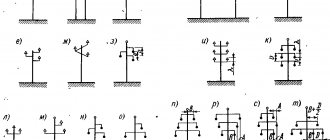
Cable installation on poles
Overhead power lines with SIP wires are called VLI. Their installation traditionally begins with clearing the area of trees, bushes, and other possible obstacles that interfere with rolling out and tensioning the wires on the supports.
When building a new power line, it is more convenient to attach the brackets for the wire to the pole on the ground before installing it. The brackets are fastened to the supports using a clamp made of corrosion-resistant steel tape. After tightening, excess tape is removed.
The poles with mounting brackets are installed and the installation of overhead power lines begins. Installation of SIP on supports takes place using components at an outside air temperature of at least 20 o C. The technology for installing SIP has its own peculiarity associated with rolling out the wire. It protects the insulation from damage. The wire is rolled out from a drum installed on the machine. SIPs are distributed on the supports using rollers and a tension rope - leader.
Manual wire rolling
The technology for unwinding from a SIP coil involves manual execution of the process, provided that the area is limited to one hundred meters and the cross-section of the phase conductors does not exceed 50 square meters. mm. Manual rolling of wires is allowed in populated areas where the span length does not exceed 50 m. Manual rolling technology has the following sequence:
- A drum with wire is installed near the first anchor support, where the power line will begin. Its distance to the pillar should be no less than the height of the support itself. The rope is attached to the end of the SIP with a mounting stocking.
- Rollers are installed on each intermediate post, while the rope is laid in them. Under the supervision of an electrician, the wire is pulled along the supports. Laying occurs smoothly without jerking with simultaneous rotation of the drum and tension of the rope. The maximum speed of manual rolling should not exceed 5 km/h, while preventing the SIP from touching the ground and any building structures.
- On the last pole of the power line, the neutral core is fixed with a clamp to the anchor bracket. A free protrusion of the cores is left behind the bracket for further connection.
- After laying out the wires on the supports, their tension begins. A winch with a measuring device - a dynamometer - is fixed to the first post. The tension is carried out with a certain force, displayed by a dynamometer. The tension force is determined from the tables, while simultaneously inspecting the quality of the wire tension between the posts. After tensioning the entire power line, the insulated wire is left to hang for a while.
- Further installation on the first post involves attaching a clamp to the bracket and fixing the zero core in it. The wiring harness is tightened with clamps, the winch and transport roller are removed. The SIP is cut off from the coil, leaving the ends of the required length.
- On the intermediate post, the wires are transferred from the roller to the clamp. Plastic wedges are used to separate the carrier core from the phase wires, while simultaneously securing it with clamps in the clamp. After removing the unrolling roller, all the cores are tightened with clamps at a distance of 150 mm from the clamp on both sides. An intermediate clamp is used to tighten and secure the phase conductors under the clamp.
At this stage, the installation of SIP in one span is completed. The following spans are mounted using a similar method.
Cable connection
Having laid the self-supporting wire on the supports, you need to connect it to the main power line and lead from it to the house:
- The cable is connected to the mains power supply using hermetically sealed clamps that ensure good contact. The connection involves stripping the insulation from the wire, after which a clamp is placed on its end. The edge of the clamp is covered with a press, squeezing it until the two parts of the matrix are closed. The end of the other wire being connected is secured in a similar way. You can connect SIPs to bare main wires using these clamps or sleeves for bare wires. In the second case, the sleeves must be supplemented with materials for sealing.
- To connect the building input to the main line from bare wires, branch clamps are used. Typically, SIPs without a neutral wire are used for branches. Then the conductors of the same cross-section of one phase are secured in one clamp with the entire bundle.
- You can connect the house input without removing the insulation from the main wire using a piercing clamp. As the bolts are tightened, the teeth of the clamp pierce the wire insulation, making contact with the aluminum core. The tightening force of the bolts is determined by the breaking of the calibration head.
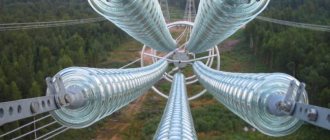
SIP design
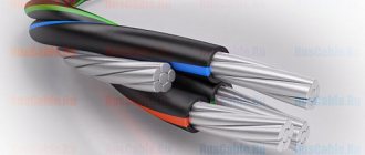
The phase aluminum wires are coated with a light-stabilizing black insulating coating. The polyethylene coating is highly resistant to moisture and ultraviolet sunlight, which destroy rubber or conventional polymer insulation.
The wires are twisted into a bundle around a zero aluminum core, in the center of which there is a steel wire. The core of the neutral core is the supporting basis of the entire cable. Some designs of SIP cables with a small cross-section and a small number of cores are light in weight, since these types do not have a steel core. SIP stands for self-supporting insulated wire.
Types and structure
Five main types of SIP wires are produced:
- SIP-1 includes three phases, each of which is twisted into a bundle of several aluminum wires around an aluminum alloy core. The wires of the fourth neutral core are twisted around a steel core. The phases are insulated with UV-resistant thermoplastic. On the SIP-1A cable brand, the neutral wire, like the phase conductors, is in an insulated sheath. Such cables can withstand prolonged heating times at 70°C.
Cable design SIP-1, SIP-1A
- SIP-2 and SIP-2A have a similar design to SIP-1 and 1A, the only difference is in the insulating shell. The insulation is “cross-linked polyethylene” - a connection of polyethylene at the molecular level into a network with wide cells with three-dimensional cross-links. This insulation structure is much more resistant to mechanical stress and can withstand lower and higher temperatures during prolonged exposure (up to 90°C). This allows the use of this brand of SIP cable in cold climates under heavy loads. The maximum voltage of transmitted electricity is up to 1 kV.
Internal structure of cable SIP-2, SIP-2A
- SIP-3 is a single-core cable with a steel core, around which wires made of AlMgSi aluminum alloy are twisted. The insulating shell made of “cross-linked polyethylene” allows the use of SIP-3 for the construction of overhead power transmission lines with voltages up to 20 kV. The operating temperature of the cable is 70°C, it can be used for a long time at temperatures ranging from minus 20°C to + 90°C. Such characteristics allow the use of SIP-3 in various climatic conditions: in temperate climates, cold or in the tropics.
Internal structure of the SIP-3 cable
- SIP-4 and SIP-4N do not have a neutral wire with a steel rod; they consist of paired wires. The letter H indicates that the wires are made of aluminum alloy. PVC insulation is resistant to ultraviolet radiation.
Design of self-supporting insulated wire SIP-4
- SIP-5 and SIP-5N - two cores have a similar structure to SIP-4 and SIP-4N, the difference is in the insulating sheath. Cross-linked polyethylene technology allows you to increase the operating time at the maximum permissible temperature by 30 percent. Power lines using SIP-5 are used in cold and temperate climates, transmitting electricity with voltages up to 2.5 kV.
Internal structure of self-supporting insulated wire SIP-5
Depending on the operating conditions and the load of electricity consumed, the brand and cross-section of the SIP cable are selected.
Rules for entering the house
After the SIP cable has been connected from the overhead line to the wall of the house, the owner is faced with the question of how to properly bring it into the house? Is it permissible to do this using a SIP cable, or should it be a copper cable that must be brought inside the house, having first connected it to the main trunk wire? To give the correct answer to this question, you must first familiarize yourself with a number of regulatory documents. First of all, you need to refer to the PUE, where there is no indication that the SIP cable can be installed inside residential premises.
Another document GOST R 52373−205 states that SIP cable can be used exclusively for laying overhead lines. Although, if you carefully read clause 10.3 of this GOST, then the SIP cable can be laid along the wall of the building, but this must be done while observing the following requirement - laying the wire on combustible bases should only be done in a corrugated or cable channel.
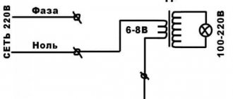
Cable entry
Based on the above, it becomes clear how exactly it is necessary to introduce an electrical cable into the house. The first step is to install a sealable box on the facade of the house. It must be outdoor rated and have a protection level of at least IP65. We already install a circuit breaker in it - two or four poles - it all depends on the voltage (220 or 380 V). We connect a SIP cable to the machine, and from the machine we lead a cable that meets the requirements into the building.
For example, this could be a VVGng wire with a cross section of 10 mm2. The place where the cable enters the house must be reinforced with a plastic or steel pipe. For the machine, try to set the rated current to a level higher than the current of the machine, which is installed in your electrical panel.
Incorrect installation option
Another option is also possible - the cable is inserted into the building directly without installing a box with a circuit breaker on the facade of the house. This option is quite acceptable, even though it will be somewhat contrary to the rules. Many electricians and companies resort to this method. Controlling organizations are also not against it; they accept this installation option without any comments. Although, if you still want to protect yourself from possible problems, we advise you to choose the first input option.
Allowable distance
To ensure that no problems arise after connecting the house to the main power line, this must be done in compliance with certain rules. A SIP cable that was introduced into a house without taking them into account may one day lead to a fire and even electric shock to a person. If we turn to the requirements of the PUE, they list the following distances that must be observed when introducing a self-supporting insulated cable into a house:
- The branch support should be located no further than 10 m from the facade of the building.
- The overhead line support should be installed no further than 25 m from the facade of the building.
- The overhead line support should be located no further than 15 m before the branch support.
- The laid cables should sag in the overhead line span by no more than 6 m.
- Installation of cables on the facade of a building is permitted at a height of at least 2.7 m.
No tags for this post.
Advantages of SIP wire
Insulated wires are superior in all respects to their predecessors, which did without a protective sheath:
- Installation speed. Instead of running 4 separate wires, you only need to run one cable.
- Ease of connection - in this regard, an electrical wire without insulation requires increased attention and careful double-checking.
- Qualification of installers. During installation, you do not need to accurately check the distance between the wires to avoid a short circuit.
- Installation cost. There is no need to use insulators - accordingly, their purchase and installation are removed from the expense item.
- The ability to connect new points without disconnecting the entire line - special clamps have been developed for such wires that pierce the insulation and are pressed tightly against the current-carrying core.
Manufacturers claim that the cable design makes it possible to almost completely eliminate the theft of electricity. Of course, we are not talking about complete protection of the cores, but making an unauthorized connection to them is indeed more difficult.
For more information about the characteristics and use of the cable, watch this video:
Selecting a section and checking the product
When going to the store to purchase a self-supporting insulated wire, pay attention to the rated current. To calculate the required value, a diagram is formed that takes into account the length of the power network sections and the load on each of them
After you calculate the approximate current value, compare it with the one indicated in the table below to select the SIP brand and cross-sectional size. Table of SIP cross-sections depending on permissible currents:
| Core cross-section, sq. mm | Permissible current for LPDE insulation | Permissible current for XLPE insulation |
| 16 | 70 | 100 |
| 25 | 95 | 130 |
| 35 | 115 | 160 |
| 50 | 140 | 195 |
| 70 | 180 | 240 |
| 95 | 220 | 290 |
| 120 | 250 | 340 |
For example, if the calculated current is 110 A, then you need to purchase SIP-1 with a cross-section of 35 square meters. mm or SIP-2 with a cross section of 25 sq. mm. The latter option is preferable, since such a wire will be lighter, stronger and more protected from wind and precipitation.
Advice! When choosing SIP, try to buy a wire with current-carrying conductors of a larger diameter than required according to the calculation. This will cover any load increases that occur in the future.
Before installing the wire, make sure that all wires are intact. To do this, use a multimeter:
- Switch the toggle switch to the “Test” position of the resistance sector, then connect the red and black probes to each other. If the device is working properly, you will hear a signal indicating that the dialing mode is activated.
- Using two probes, touch both ends of the SIP wire. If there is no damage to the conductor, you will hear a beep indicating that the charge has passed from one end to the other.
- These steps will need to be repeated for each core.
Similar checks should be carried out for a toggle switch installed in the resistance measurement sector from 200 Ohm to 200 kOhm. If the display shows “0”, then the conductor is intact, “1” - there is a break in the line.
Advantages and disadvantages
Let us list the main advantages of SIP wires:
- Easy to install and lay. The process takes less effort and time compared to installing other bare wires. There is no need to attach the conductors to insulators.
- Reducing the likelihood of unauthorized connection to the line. Switching requires certain skills and work experience, so not everyone can perform such actions.
- SIP insulating shells are made from high-quality material that repels wet snow and condensation, which eliminates serious icing of the line. If ice appears, it is in small quantities.
- Reducing the likelihood of electric shock. The presence of conductor insulation reduces the risk of electric shock during repair work and maintenance of power lines. Many operations can be performed without turning off the voltage.
- Economical. Due to the SIP design, the wire is less susceptible to breakage. Minimal funds are spent on maintenance; the wire can be installed on the facades of residential buildings (with the exception of some categories), thereby reducing the number of installed supports.
- Reduced inductance. Due to the low reactance in the wire, the amount of power and voltage losses is significantly less. This eliminates the formation of current pickups and allows you to mount self-supporting insulated insulated wires on supports for low-voltage lines.
The disadvantages include:
- High cost compared to simple bare wires. For quite objective reasons, the price of SIP is significantly higher than the cost of conventional non-insulated cables.
- When using SIP, you must contact qualified specialists. Only they can perform high-quality installation and maintenance of power lines using these wires. This is due to the fact that such products appeared relatively recently, so they have not yet become so widespread. Add to all this the fact that domestic electrical supply systems are not suitable for the transition to self-supporting insulated conductors.
Specifications
When choosing a specific brand of SIP wire, it is important to pay attention to the compliance of the characteristics and parameters with the individual requirements of the consumer and the installation method. To do this, the following technical characteristics are taken into account:
To do this, the following technical characteristics are taken into account:
- Number of cores - as a rule, models with the number of current-carrying elements from 1 to 4 are used;
- Cross-section – for different SIP models, this parameter varies from 16 to 240 mm²;
- Voltage class - there are two categories in total - up to 1 kV (SIP-1, 2, 4, 5) and up to 35 kV (SIP-3);
- Temperature regime - implies a normal operating temperature at which the wire will transmit electricity for a long time without losing its parameters;
- Permissible short-term heating - can occur in emergency modes, but should not exceed more than 8 hours of the annual load;
- Bending radius - determines the ability to bend the wire without compromising the mechanical strength of the insulation and its dielectric properties.
All technical characteristics compared for all brands are shown in the table below:
Table comparing characteristics of SIP brands
| Wire brand | SIP-1 | SIP-2 | SIP-3 | SIP-4 | SIP-5 |
| Number of current-carrying cores, pcs. | 1 ÷ 4 | 1 ÷ 4 | 1 | 2 — 4 | 2 — 4 |
| Core cross-section, mm2 | 16 ÷ 120 | 16 ÷ 120 | 35 ÷ 240 | 16 ÷ 120 | 16 ÷ 120 |
| Zero core, bearing | aluminum alloy (with steel cores) | aluminum alloy (with steel cores) | absent | absent | absent |
| Current-carrying core | aluminum | aluminum | aluminum alloy (with steel cores) | aluminum | aluminum |
| Voltage class, kV | 0.4 ÷ 1 | 0.4 ÷ 1 | 10 ÷ 35 | 0.4 ÷ 1 | 0.4 ÷ 1 |
| Core insulation type | thermoplastic polyethylene | light stabilized polyethylene | light stabilized polyethylene | thermoplastic polyethylene | light stabilized polyethylene |
| Operating temperature | -60оС ÷ +50оС | -60оС ÷ +50оС | -60оС ÷ +50оС | -60оС ÷ +50оС | -60оС ÷ +50оС |
| Permissible heating of cores during operation | +70оС | +90оС | +70оС | +90оС | +90оС |
| min wire bending radius | not less than 10 Ø | not less than 10 Ø | not less than 10 Ø | not less than 10 Ø | not less than 10 Ø |
| Life time | at least 40 years | at least 40 years | at least 40 years | at least 40 years | at least 40 years |
| Application | branches from overhead lines; — power supply to living quarters; - household construction laying along the walls of buildings and structures. | branches from overhead lines; — power supply to living quarters; - household construction laying along the walls of buildings and structures. | for installation of overhead lines with voltage 6-35 kV | branches from overhead lines; — power supply to living quarters; - household the buildings; — laying along the walls of buildings and structures. | branches from overhead lines; — power supply to living quarters; - household the buildings; — laying along the walls of buildings and structures. |