Good day to all! In the last article, I talked about determining the overall power of a RG transformer and determining the filling factor of the window kok of the transformer. This data is not enough to select a transformer. Its parameters are significantly influenced by specified quantities, for example, voltage, frequency, mode and operating conditions. Often the type of transformer, its core and windings are known initially, otherwise they should be selected based on the given conditions.
To assemble a radio-electronic device, you can pre-make a DIY KIT kit using the link.
Features of the structure of the transformer core
The transformer is used to convert alternating current voltage.
It consists of a core with two or more windings. An alternating voltage is supplied to one of the coils. The current passing through it causes a change in time of the magnetic flux in the core. This flow penetrates all the windings and, according to the law of electromagnetic induction, induces an EMF in them. Depending on the ratio of the number of turns in the coils, the initial voltage in the secondary winding increases or decreases in comparison with the applied one.
The core is necessary for more efficient voltage transformation to reduce leakage losses.
The transformer core experiences significant exposure to an alternating magnetic field. This leads to the occurrence of eddy currents. As a result, the magnetic circuit heats up, which leads to energy loss.
The cores are made of steel, the magnetization reversal of which also leads to wasted energy consumption.
Main dimensions of the transformer
The geometric dimensions of the transformer in most cases are decisive for its technical and economic indicators. The main dimensions of a transformer coil are its height and width (thickness), limited by the dimensions of the core. For the core, the main dimensions will be: the width of the rod carrying the coil a ; rod thickness b ; window width c and window height h .
Main dimensions of transformer cores of different types.
In core specifications and literature, the unit of measurement for dimensions is usually millimeters mm ( mm ).
To simplify calculations and some unification of cores, the so-called basic size was introduced in domestic literature and calculation methods. One of the main transformer sizes can be taken as the base one. In most cases, the width of the rod a is taken as the base size. Then the geometry of the core is described by the following relations
Using the base size a and dimensionless coefficients x, y, z, you can express all the geometric characteristics of the transformer: lengths, sections, surfaces and volumes. For example, core cross-section Sc = ab, and taking into account the base size Sc = ya2. Volume of armored transformer BT
and taking into account the base size
that is, the geometric parameters of the transformer, taking into account the basic size, are expressed by formulas like
where k – can have a value from 1 to 3, depending on the type of quantity (1 – length; 2 – area, surface, section; 3 – volume);
φi is a function of the geometric characteristic of the transformer, the index “i” indicates a specific characteristic.
| Transformer characteristics | Function designation | Characteristic designation |
| Average magnetic line length | φl | lc= φla |
| Average length of coil turn | φw | lw=φwa |
| Core cross section (geometric) | φs | sc= φsa2 |
| Total cross-section (area) of the core window | φok | sok= φoka2 |
| Coil cooling surface area | φpk | Pk= φpka2 |
| Core cooling surface area | φps | Ps= φpsa2 |
| Volume occupied by the coil | φk | Vk= φka3 |
| Volume occupied by the core | φс | Vс= φсa3 |
Geometric characteristics of the transformer and their functions.
Geometry functions are dimensionless, making it easier to analyze different types of transformers.
How to reduce losses
The magnitude of magnetization reversal losses depends on several factors:
- properties of the substance from which the core is made. Materials that are difficult to magnetize are also difficult to remagnetize. And the more energy is consumed, which is expressed in heating;
- magnetization reversal frequencies;
- the highest value of magnetic induction.
Losses are reduced through the use of special transformer steel. It requires less energy for magnetization reversal compared to other substances.
Eddy currents reach their greatest values in massive conductors due to their low resistance. To reduce them, it is necessary to increase the electrical resistance. This is achieved by assembling a core from separate sheets. The thickness of the steel plates is selected to be no more than 0.5 mm.
To prevent the sheets from melting together when heated, the plates are isolated from each other to reduce eddy current losses. Varnish and scale are used as a separator. There are chemical methods for insulating steel sheets. The interlayers provide strong resistance to eddy currents and stop their effect, which significantly reduces energy losses.
Core Material Selection
At the moment, a large number of magnetic materials have been developed from which transformer cores are made. The main ones are:
- Electrical steels are used at frequencies up to tens of kHz and have a saturation induction BS ≤ 2 Tesla. At a frequency of 50 Hz, steel with a thickness of 0.35 - 0.5 mm is used, and above - with a thickness of 0.05 - 0.15 mm. For example, 3411, 3412, 3421, 3422, etc.
- Electrical alloys are used at frequencies up to 100 kHz with saturation induction up to 1.5 Tesla. They are made in the form of a tape with a thickness of 0.05 – 0.1 mm. For example, 79NM, 34NKMP, etc.
- Ferrites are used in a wide frequency range from units of kHz to units of MHz with saturation induction up to 0.5 Tesla. They are manufactured in the form of various types of cores. For example, 1500NM3, 700NM, N72, M33, etc.
- Magnetodielectrics have an insignificant magnetic permeability up to hundreds of units, and saturation induction and operating frequency in a wide range depending on the type:
— carbonyl iron (BS < 2.18 T, frequency up to 100 MHz), for example, MP-20, MP-100, etc.;
— alsifers (BS = 0.2 – 0.5 T, maximum frequency 20 – 700 kHz), for example, PM-90, HF-32, etc.;
— pressperms (BS = 0.5 – 0.8 T, frequency up to 100 kHz), for example, MP-60, MP-140, MP-250, etc.
The main parameters of magnetic materials are: saturation induction BS, residual induction Br, absolute magnetic permeability μa, specific losses of Ore per unit volume or mass, coercivity Hc, squareness of the hysteresis loop Br/BS.
The core material should allow the production of cores of the smallest volume (high μa value) and have minimal power losses (low Rud value). But often these requirements are contradictory, so the necessary choice of material should be based on achieving the best value for the most important parameter for the product. Most often, developers choose the weight and size characteristics of a material with acceptable power losses as the main limitation.
With the choice of core material, it is necessary to determine the core fill factor kc depends on the type of core. For pressed materials (ferrites, magnetodielectrics) ks = 1, and for strip and laminated materials it depends on the thickness of the magnetic material
| Tape thickness, mm | 0,35 | 0,15 | 0,1-0,08 | 0,05 | 0,02 |
| Core fill factor, kc | 0,93 | 0,9 | 0,85 | 0,75-0,8 | 0,65-0,7 |
For approximate calculations in the case of strip and laminated cores, ks = 0.9 can be taken.
Main types of cores
Transformers have different areas of application, technical characteristics, and dimensions.
They also differ in the type of magnetic circuits. Structurally, the cores are divided into three main types: The rod core is designed in the shape of the letter P and consists of two rods connected by a yoke. If necessary, protect the windings from external influences using armored magnetic cores. The yoke is located on the outer part and completely covers the rod with the winding located inside.
Cores are also classified according to the method of assembling the plates:
- set of stamped plates. The advantages of magnetic cores made from sheets include the possibility of their manufacture from not very durable materials;
- wound metal tapes. Such cores utilize magnetic energy more fully, but at the same time have an increased level of losses. Toroidal winding of tapes is the most complex, but energetically the most favorable.
There are differences in the connection of the rods to the yoke. They are collected in two ways:
- end-to-end, when all elements are assembled from plates separately. They are connected into a single core at the last stage of transformer assembly: after the windings are laid;
- intertwined. Such magnetic cores are called laminated. They have almost no losses at the connection points.
Features of impulse loads
For devices carrying pulsed loads, special transformers are used. They are capable of converting voltage and current under pulsed loads and withstanding their destructive effects. The types of cores of pulse transformers do not differ in shape from other types of devices.
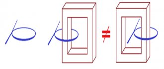
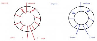
Most often, the magnetic core is made in the form of a ferrite torus. The windings are wound on it in a special way: in the primary coil they are laid counterclockwise, and in the secondary coil they are laid clockwise.
Such a transformer can be made independently; you just need to take into account the requirements for conservation of momentum.
Converter power calculation
Each transformer has technical characteristics specified in the passport. It may be necessary to carry out independent winding and power calculations if the data is lost. The power value is important to determine whether a particular inverter can be used.
Before determining the power of the transformer based on the cross-section of the core, the type of magnetic circuit is studied. If the core has a W shape, perform the following calculations:
- measure the thickness of the set of plates;
- measure the central part;
- the results obtained are multiplied.
What is a magnetic core in a transformer? Why is there a gap needed and more?
Mains and pulse transformers have a core or magnetic circuit made of different materials; this article will talk about this detail.
A magnetic core is a part of a transformer designed to pass a magnetic flux. This flux in a network transformer appears when the primary network winding is connected to a 220V network, which has a sinusoidal voltage waveform. An electromagnetic field is formed near this coil, the magnetic component of which is transmitted by the magnetic core and it becomes a magnet whose poles change 50 times north and 50 times south in one second. If you insert another step-down coil onto the magnetic circuit, then when a load is connected to it, an emf is induced in it.
If you measure the resistance of the TS-180 network winding, the readings will be about 6.4 Ohms, and if you take a 6.4 Ohm resistor and plug it into a 220V network, it will break or blow out the plugs. The fact is that the resistance of the resistor is active, this will be shown by the ohmmeter, and the resistance of the network winding at an alternating voltage of 220V is reactive, and it is precisely this that provides the resistance of 220V. The core in the coil increases the reactance and inductance of the winding.
The magnetic core is made of special transformer steel-iron with silicon (soft magnetic material), with high resistivity and minimal residual magnetization, a narrow hysteresis loop, and high magnetic permeability. The magnetic core is affected by Foucault currents, to reduce them the core is overlapped and laminated, and the plates are insulated from each other with varnish or a layer of oxide. The high resistivity of the core is also due to Foucault currents.
You cannot use another steel in the core, it will start to heat up and the transformer will not work well. The core may go into saturation, this is when the magnetic circuit becomes a magnet as much as possible. In this mode, the transformer will begin to emit impulse noise, which can affect the operation of radio components.
To operate in switching power supplies, a ferrite core is used, which can operate at frequencies of tens of kHz with pulses. This is also a ferromagnet, but is made of iron oxide and other additives and materials. It is not overlapped, since the Foucault currents in the core are extinguished due to due to the high resistivity of the material. The gap is made so that the core does not become saturated from magnetization, which can be caused by the constant component of the signal (non-magnetic gap).
Network and pulse transformers can be wound on a toroidal core to reduce stray fields. They are more efficient compared to conventional cores and have smaller dimensions, but winding on rings is labor-intensive, and on a ferrite ring it is also more difficult to create a gap, although it is commercially available rings with clearance.
The magnetic antenna has a ferrite core. Marking 400NN. 400 is the magnetic permeability, the higher it is, the lower the operating frequency of the ferrite. In microwaves, the core in the circuits is brass or aluminum.
Transformer steel composition
The material is made not only from silicon, but also an alloy with iron. The addition of this element causes the force coefficient to increase and the electrical power resistivity to increase when compared to grades without silicon.
If you add a certain amount of silicon to the composition, this will lead to a decrease in the individual weight of iron oxides.
According to the chemical composition, this material can be classified as an alloy metal due to the presence of silicon in an amount of up to 0.5%.
In transformer iron, the addition of foreign impurities is in the range of 3-4.5%.
A little history
Thanks to the English physicist Michael Faraday, in 1831, humanity became acquainted with electromagnetic induction. The great scientist was not destined to become the inventor of the transformer, since his experiments involved direct current. The prototype of the device can be considered the unusual induction coil of the Frenchman G. Ruhmkorff, which was presented to the scientific world in 1848.
In 1876, Russian electrical engineer P. N. Yablochkov patented an alternating current transformer with an open core. The device owes its modern appearance to the English brothers Hopkinson, as well as the Romanians K. Tsiperanovsky and O. Blati. With their help, the design acquired a closed magnetic circuit and has preserved the circuit to this day.
Types of magnetic cores
Design and operating principle
Mandatory elements of almost any voltage conversion device are insulated windings formed from wire or tape. They are located on a magnetic circuit represented by a core made of ferromagnetic material. Communication between the coils is carried out using magnetic flux. When working with high-frequency currents (100 kHz or more), there is no core.
Transformer operating principle
The operating principle of a transformer combines the basic postulates of electromagnetism and electromagnetic induction. It can be considered using the example of a simple device with two coils and a steel core. The supply of alternating voltage to the primary winding leads to the appearance of a magnetic flux in the magnetic circuit, after which an induced emf appears in the secondary and primary windings; if you connect a load to the secondary winding, current will flow. The frequency of the output voltage remains unchanged, and its value depends on the ratio of the turns of the coils.
Transformers can be step-up and step-down, to determine this you need to find out the transformation ratio , with its help you can find out which transformer. If the coefficient is less than 1, then the transformer is step-up (this can also be determined by the values; if there is more in the secondary winding than in the primary, then it is step-up), and vice versa, if K>1, then it is step-down (if there are fewer turns in the primary winding than in the secondary).
- U1 and U2 – voltage in the primary and secondary windings,
- N1 and N2 – number of turns in the primary and secondary windings,
- I1 and I2 – current in the primary and secondary windings.
Properties of silicon
Silicon is called the main material of semiconductor electronics. It is used to manufacture integrated circuits, diodes, transistors, solar panels, photodetectors and other devices.
It is a semiconductor whose electrical properties depend on impurities. It is transparent to infrared rays. At low temperatures it exhibits chemical inertness and a thin oxide film forms in air. Oxidation of silicon occurs when heated to 400 degrees. Soluble in many molten metals.
Operating modes
The characteristics of transformers are determined by operating conditions, where the load resistance plays a key role. The following modes are used as a basis:
- Idle move. The outputs of the secondary circuit are in an open state, the load resistance is equal to infinity. Measuring the magnetizing current flowing in the primary winding makes it possible to calculate the efficiency of the transformer. Using this mode, the transformation ratio is calculated, as well as losses in the core;
- Under load (working). The secondary circuit is loaded with a certain resistance. The parameters of the current flowing through it are directly related to the ratio of the turns of the coils.
- Short circuit. The ends of the secondary winding are short-circuited, the load resistance is zero. The mode informs about losses that are caused by heating of the windings, which in professional language is referred to as “copper losses”.
Short circuit mode
Information about the behavior of the transformer in various modes is obtained experimentally using equivalent circuits.
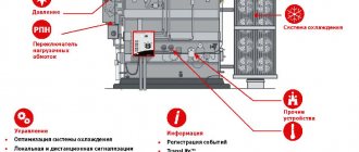
Menu
Switching power supplies can be made with or without galvanic isolation. The former, as a rule, contain a regulated or unregulated inverter or converter, the most important winding unit of which is the transformer. The design of the transformer depends on the type and operating mode of the inverter or converter. Let's consider some types of winding products for various types of such converters.
Unregulated and adjustable push-pull inverters (DC-to-AC converters) and converters (DC-to-DC converters) can be made according to a midpoint circuit (Fig. 1a), half-bridge (Fig. 1b) and bridge (Fig. 1c) circuits . In a half-bridge inverter circuit, the primary winding of the transformer is connected through capacitors, so the DC component of the current (bias current) is completely absent. In the other two circuits, as well as in a half-bridge converter in which the transformer is loaded onto a rectifier, core bias is completely absent only in the ideal case - with complete symmetry of the circuit, with equal voltage drop across the open switches and rectifier diodes and with the same turn-on, turn-off, restoration of the reverse resistance of key elements and diodes of both arms. If these conditions are not met, a certain constant component may appear, which will lead to an asymmetrical operating mode of the transformer core, and this circumstance in some cases must be taken into account.
Rice. 1
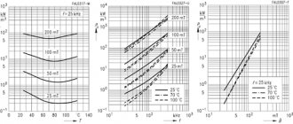
Since the transformer core operates in strong fields with a large range of magnetic induction, it is advisable to choose the so-called “power” grades of manganese-zinc ferrites, for example, N87 or N97 produced by Epcos up to a frequency of 500 kHz or N49 from Epcos up to 1 MHz or their analogues produced by others firms At conversion frequencies up to 30 kHz, domestic material M2500NMS2, as well as amorphous magnetic alloys, can be used. It is not advisable to use powder magnetic materials (mo-permalloy, etc.), since they have a low magnetic permeability and many of them are more expensive than ferrites. When choosing a core material, it is necessary to take into account the amount of loss in the core, which depends on frequency and magnetic induction and increases with increasing both parameters. Comparative dependences of the specific losses on frequency for some soft magnetic materials at a magnetic induction of 0.1 T are shown in Fig. 2.
Rice. 2
The core configuration for push-pull converters can be any. The most commonly used are ring (toroidal) cores (especially for low and medium power devices). Transformers on them, all other things being equal, have minimal leakage inductance, which reduces voltage surges on power switches, noise emissions, and reduces the output resistance of the transformer. In addition, ring cores are cheap. The disadvantages of toroidal coils are the higher labor intensity of winding and the need to insulate the core (domestic cores are produced without coating, imported ones - both without coating and with an insulating coating designed for a certain test voltage value). It is also possible to use split cores of armor and rod construction. Domestic cores of the KV type (imported analogues of RM), as well as Ш-shaped cores and their modifications (domestic Ш, imported EE, EI, EFD, ER, ETD, etc.) are widely used. HF (RM) cores fit into a square plan, which is convenient for placing them on the board. They have a round reel with either one section or two or more, which is convenient and easy to wind. However, due to the higher leakage inductance, in some cases it is necessary to use technological complications in the winding, as well as to increase the damping circuits in the converter circuit, which in turn slightly reduces the efficiency. Cores of type B (imported analogues of P) are similar to HF, but round in plan, less convenient when placed on the board and are used less frequently.
EP cores are quite convenient, they fit into a rectangle (almost a square), have an easy-to-wind coil, which the core covers on all sides except one, facing the board. EFD type cores are positioned horizontally and have a reduced height. Low-profile cores with LP indexes are used in cases where a particularly low product height is required. In this case, printed windings in the form of multilayer printed circuit boards are often used. For high power and high voltage transformers, U-shaped cores can be used. Increased leakage inductance at high output voltages and low currents is not a big drawback, but this design with a large window allows you to place a high-voltage winding in which insulation takes up a lot of space.
Rice. 3
Single-cycle forward converters are made mainly according to one of three schemes: with a demagnetizing winding (Fig. 3a), without a demagnetizing winding with energy recovery into a capacitance, including parasitic one (Fig. 3b), and on two transistors and two diodes according to the so-called single-ended half-bridge circuit (Fig. 3c). In any of these cases, the energy from the power source is transferred to the load in the forward direction, without storing energy in the transformer, in which only a small amount of energy is stored due to the magnetizing current of the primary winding. The recovery (return) of this energy, at which the transformer is demagnetized, occurs differently in each of the circuits.
In the first case, a demagnetizing winding is used for this, and when developing a transformer, it is necessary to ensure the maximum possible connection between it and the primary winding, taking into account the operating voltage. In the second, recuperation occurs in a capacitance, and a significant surge occurs on the winding during reverse motion, which must be taken into account when choosing circuit elements and when designing a transformer. In the third case, energy is recovered into the power source through opening regenerative diodes, and through the same primary winding, which ensures the absence of surge on it and the most reliable demagnetization of the transformer. In any case, there is a constant component of the primary winding current, and the transformer core is remagnetized according to a partial cycle of the hysteresis loop from the maximum induction Bm to the residual induction Br. In this case, the greater the difference Bs–Br, where Bs is the saturation induction of the material, the better. For this application, it is also preferable to use grades of ferrites designed to operate in high fields. The core configuration can be any. Both ring cores and any others mentioned earlier can be used.
Rice. 4
Single-ended flyback converters (Fig. 4). The transformer operates by storing energy in the forward stroke and transferring energy to the load in the reverse stroke. The operating mode of the transformer is similar to the operating mode of the inductor, i.e. there is a constant component of the winding current and a magnetizing field. Magnetization occurs through the primary winding, and demagnetization occurs when energy is transferred to the load through the secondary winding. Three operating modes of a transformer are possible, by analogy with a choke: a continuous current mode, in which the energy stored in the magnetic field of the transformer does not decrease to zero during the reverse stroke; intermittent current mode, when energy is transferred to the load completely during part of the reverse stroke duration, and the boundary mode between the first two. The most commonly used are boundary mode and intermittent current mode. Sometimes a continuous mode is selected, but it is only possible at a certain load, and when the load current decreases, the transformer operation mode inevitably becomes intermittent.
Since such a transformer always operates with magnetization, it can be made either on a split core made of “power” grade ferrite with a non-magnetic gap, or on a ring or split core made of magnetodielectric without a gap. The configuration of ferrite cores can be any, but there must be a gap. Differences depending on the configuration will consist of different leakage inductance, different dimensions, manufacturability and cost.
Ferrite core transformers with a gap have a more stable inductance as current changes, but then their inductance drops sharply when the core reaches saturation. For transformers with cores made of magnetodielectrics, when the current changes, the inductance changes smoothly, but to a greater extent, and sharp saturation is not observed. The latter characteristic is preferable, although both are suitable for flyback converters. The advantage of ferrites in higher magnetic permeability in this application is lost, since the value of the equivalent permeability is small and is determined mainly by the size of the non-magnetic gap.
Since the transformer operates in high fields, the amount of core loss is important. Among magnetodielectrics, mo-permalloy has the best technical parameters, but this material is relatively expensive. If you need to reduce the price, then use Sendust or Cool Mµ, but this may increase the dimensions of the product, since in order to reduce losses to the same value as mo-permalloy, you will have to reduce the magnetic induction in the core. As a last resort, you can use cores made of atomized iron, but in this case the dimensions of the transformer may increase even more, but the price will be lower. Transformers based on ring cores made of magnetodielectrics have minimal leakage inductance compared to split cores and provide a minimum amount of parasitic voltage surges.
The chokes of forward push-pull and single-stroke converters with galvanic isolation (L1 in Fig. 1 and 3) operate in approximately the same modes. In push-pull circuits, the mode is easier, since the throttle operates at double the conversion frequency and with a shorter pause duration (as a rule). The inductor works with energy storage, like a flyback converter transformer, but in the general case it has one winding, through which energy is both stored and transferred to the load. Converter chokes without galvanic isolation and power factor corrector chokes operate in a similar mode. The inductor core operates in strong fields with a large direct current component. Therefore, as in the previous case, any split ferrite cores with a gap or magnetodielectric cores without a gap are suitable, taking into account all the considerations expressed earlier.
Power filter chokes, which are usually used in the second and subsequent filtering links (the second link of the power supply output filter, decoupling power filters on functional equipment boards, etc.) - L2 in Fig. 1, 3 and 4—operate at a high level of bias current, but at a low level of the alternating component. In this case, the operating range of magnetic induction in the core is small and losses in the inductor are determined more by losses in copper than by losses in the core. For this case, ferrite open cores (rods, dumbbells), ferrite cores with gaps, as well as ferrite rings, beads, tubes (mainly for single-turn chokes) can be used. In the latter case, despite the fact that the core operates with bias, the remaining magnetic permeability is quite sufficient to reduce the level of ripple, noise and interference several times, and the stability of the inductance when the current changes is not of fundamental importance. Chokes on cores made of magnetodielectrics can also be successfully used, and the most suitable material in this case would be atomized iron, since with a small variable component there is no point in using expensive materials, for example mo-permalloy.
The increased value of losses in the core will even play a positive role and contribute to the transfer of noise and interference energy into heat. All of the above also applies to the input filter chokes of DC/DC converters and DC/AC inverters (Fig. 5a), since they have a similar operating mode.
Rice. 4
Line filter chokes for AC/DC power supplies are used in three versions:
Current-compensated chokes , designed to suppress common-mode noise components (L1 in Fig. 5b, c), contain two identical windings connected to each other through the magnetic field of the core. Biasing of the core by a current of frequency 50 Hz does not occur in them, since the currents in both windings create fields directed towards and compensating each other. For such a choke, ferrite cores without a gap can be used, and highly permeable grades of ferrites are preferred, since the core operates in weak fields created by interference currents, and in order to obtain the highest possible resonant frequency of the choke, it is desirable to obtain a given inductance with a minimum number of turns. The use of magnetodielectrics is impractical due to low magnetic permeability and lack of magnetization, as well as the low cost of ferrites. Structurally, the choke is often made on a two-section frame with a U-shaped or W-shaped core or on a ring core with windings wound on different sides of the ring.
Single- and two-winding chokes (L2 in Fig. 5b and L2 and L3 in Fig. 5c), in which the windings for low-frequency currents (50 Hz) are switched on accordingly, are designed to suppress differential (anti-phase) noise components in the power supply wires. Here, at a low level of interference voltage, magnetization occurs with a large current consumption of the power supply, operating at a frequency of 50 Hz, which in this situation is equivalent to magnetization with direct current. Therefore, for such chokes it is necessary to use ferrite cores with a gap or magnetodielectric cores. The permeability of ferrite cores is not of fundamental importance, since the inductance coefficient of a particular core is determined mainly by its geometry and the size of the non-magnetic gap. High-frequency variable component cores operate in weak fields, and losses in the core material are not of great importance and even play a positive role. Of the magnetodielectrics, it is advisable to use ring cores or W-shaped cores without a gap made of atomized iron (Iron Powder), as they are the cheapest and best meet the requirements.
Thus, for each winding product operating as part of a switching power source, the most suitable configuration and core material can be selected.
Classifications
Transformers are classified according to a number of parameters, such as:
- Purpose. Used: for changing voltage, measuring current, protecting electrical circuits, as laboratory and intermediate devices.
- Installation method. Depending on the location and mobility, the transformer can be: stationary, portable, internal, external, support, busbar.
- Number of steps. The devices are divided into single-stage and cascade.
- Rated voltage. There are low and high voltage.
- Winding insulation. The most commonly used are oil-paper, dry, and compound.
In addition, converter devices come in different types, each of which has its own classification system.
Power
The most widely used the power transformer . Devices with direct conversion of alternating voltage, designed for high power, are in demand in various areas of the electric power industry. They are used on power lines with voltages of 35–1150 kV, in city power networks operating with voltages of 6 and 10 kV, and in providing end consumers with voltages of 220/380V. The devices provide power to all kinds of electrical installations and devices in the range from fractions to hundreds of thousands of volts.
Power transformer
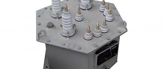
Measuring
Current transformers (CTs) reduce the current to the required levels. The scheme of their operation is distinguished by the sequential connection of the primary winding and load. At the same time, the secondary winding, which is in a state close to a short circuit, is used to connect measuring instruments, actuators and indicator devices. With the help of TA, galvanic isolation is carried out, which makes it possible to avoid using shunts during measurements.
High voltage CT(left) and low voltage CT(right)
With the help of voltage transformers (VT) , the same as TA only in voltage. In addition to converting input parameters, electrical equipment and its individual elements are protected from high voltage.
High voltage transformer (left) and low voltage transformer (right)
Pulse
If it is necessary to convert pulsed signals, pulse transformers (IT) are used. By changing the amplitude and polarity of the pulses, the devices maintain their duration and practically do not affect the shape.
Autotransformer
In autotransformers, the windings form one circuit and interact through electromagnetic and electrical communication. Unlike other types of converters, devices can contain only 3 outputs, allowing you to operate with different voltages. The devices are distinguished by their high efficiency, which is especially noticeable with a slight difference in input and output voltage.
Single-phase (left) and three-phase (right)
Without galvanic isolation, representatives of this type increase the risk of high-voltage shock to the load. A prerequisite for the operation of devices is reliable grounding and a low transformation ratio. The disadvantage is compensated by lower consumption of materials during manufacturing, compactness and weight, and cost.
Dividing
For isolation transformers, interaction between the windings is eliminated. The devices increase the safety of electrical equipment in the event of damaged insulation.
Isolation transformer
Coordinator
Matching transformers are used to equalize resistance between stages of electronic circuits. While maintaining the signal shape, they play the role of galvanic isolation.
Peak transformer
Using a peak transformer, sinusoidal voltage is converted into pulse voltage. In this case, the pulses change polarity with each half-cycle.
Twin throttle
A feature of a dual inductor is the identity of the windings. The mutual induction of the coils makes it more efficient than standard chokes. The devices are used as input filters in power supplies, audio and digital equipment.
Twin throttle
Welding
In addition to the above, there is the concept of welding transformers. Specialized devices for welding work lower the voltage of the household network while simultaneously increasing the current, measured in thousands of amperes. The latter is adjusted by dividing the windings into sectors, which affects the inductive reactance.
Welding transformer
The transformer magnetic core is made of electrical steel for
Transformer design
Magnetic circuit design. The magnetic core is the structural basis of the transformer. It serves to conduct the main magnetic flux. To reduce the magnetic resistance along the path of this flow and, consequently, reduce the magnetizing current, the magnetic circuit is made of special electrical steel. Since the magnetic flux in the transformer changes over time, to reduce losses from eddy currents in the magnetic circuit, it is assembled from separate steel sheets electrically insulated from each other. The thickness of the sheets is chosen the smaller, the higher the frequency of the supply voltage. At a frequency of 50 Hz, the thickness of the steel sheets is taken to be 0.35 - 0.5 mm. Insulation of sheets is most often carried out with a varnish film, which is applied on both sides of each sheet.
In the magnetic circuit there are rods and yokes. The rod is the part of the magnetic circuit on which the windings are located, and the yoke is the part that does not carry the windings and serves to close the magnetic circuit (Fig. 1).
Depending on the relative position of the rods, yokes and windings, magnetic circuits are divided into rod and armored . In core magnetic circuits, the yokes are adjacent to the end surfaces of the windings, without covering their side surfaces. In armored magnetic circuits, the yokes cover not only the end but also the side surfaces of the windings, as if covering them with armor.
Magnetic cores of single-phase transformers are shown in Fig. 2 and 3. The armored magnetic circuit (Fig. 2) has one rod and two yokes covering the windings.
Each yoke closes half of the magnetic flux of the rod, so the cross-sectional area of each yoke is 2 times less than the cross-sectional area of the rod. In the core magnetic circuit (Fig. 3) there are two rods, each of which contains half of windings 1 and 2. The halves of each winding are connected to each other in series or in parallel. With this arrangement of windings, magnetic leakage fluxes are reduced and the characteristics of the transformer are improved. In three-phase circuits, three single-phase transformers can be used, the windings of which are connected according to a three-phase circuit (Fig. 4). Such a transformer is called a three-phase group of single-phase transformers.
However, three-phase transformers with a common magnetic system for all phases are more often used. The armored design of the magnetic core of a three-phase transformer is shown in Fig. 5. It can be considered as three armored magnetic cores for single-phase transformers, stacked on top of each other.
Three-phase transformers often have three legs and two yokes (Figure 6). The possibility of using such a magnetic circuit for transformation in three-phase circuits can be seen from Fig. 7.
If you arrange three single-phase transformers as shown in Fig. 7, a, then three rods 1 - 3 can be structurally combined into one. But since in a symmetrical three-phase system the geometric sum of the magnetic fluxes of the three phases is zero, i.e. FA + ФB + ФС = 0, then this rod can be removed and constructive diagram 7, b is obtained. If we reduce the length of the yokes of the magnetic core of phase B, we will obtain a magnetic core with rods located in the same plane (Fig. 7, a). Compared to the diagram in Fig. 7, b magnetic circuit shown in Fig. 7, c, has some magnetic asymmetry, since the magnetic circuit in this case is a magnetic circuit with two nodes and three branches, of which the middle one is shorter than the outer ones. As practice shows, such asymmetry is not significant.
On each rod of a three-phase core magnetic circuit, both windings of the same phase are located. In rod magnetic circuits, the magnetic flux of the yoke is equal to the magnetic flux of the rod and the cross-sectional area of the steel in the yoke should be equal to or slightly larger (to reduce magnetic losses) than the cross-sectional area of the steel in the rod. The most widespread are rod-type magnetic cores (Fig. 6). Sometimes in high-power transformers, to reduce their height dimensions to sizes at which it is possible to transport assembled transformers by rail, armored magnetic cores are used (Fig. 8 and 9).
The height of these transformers is reduced due to the yokes, which, compared to the yokes of core magnetic circuits, have a height that is 2 times less for single-phase transformers and √3 times less for three-phase ones. In Fig. For comparison, 8 and 9 show the heights of the rod h C and the armored rod h BS magnetic cores. In these figures, the windings are shown conventionally (without division into LV and HV windings).
Decoding the main parameters
The diversity in design and wide range of parameters of transformers have led to the need for their marking according to a special standard. Without having a technical description at hand, the characteristics of the device can be determined by the information printed on its surface, expressed in an alphanumeric code.
The marking of power transformers contains 4 blocks.
You can download and view GOST 15150 here (will open in a new contribution in PDF format): View file
Let's decipher the first three blocks:
Decoding of markings: 1,2,3 blocks
- The first letter "A" is attached behind the autotransformers. In its absence, the letters “T” and “O” correspond to three-phase and single-phase transformers.
- The further presence of the letter “P” informs about devices with split winding.
- The third letter means cooling; the oil natural cooling system is assigned the letter “M”. Natural air cooling is marked with the letter “C”, oil cooling with forced airflow is designated “D”, with forced oil circulation – “C”. The combination “DC” indicates the presence of forced oil circulation with simultaneous air blowing.
- The letter “T” marks three-winding converters.
- The last sign characterizes the features of the transformer:
- “N” – on-load tap-changer (voltage regulation under load);
- space – switching without excitation;
- “G” – lightning protected.
Transformers price
The price of a transformer varies widely and depends on many factors. This takes into account the type and purpose, power and other electrical parameters. The cost of devices is reflected in the complexity of production and the materials used. Protection and other features are also important.
A transformer from a well-known manufacturer cannot be cheap. However, the buyer can be sure that the device he purchased fully complies with the specified characteristics, will not fail the first time it is turned on, and is guaranteed to work out its intended life.
High-voltage transformers can be assessed by their power, that is, if the power of a transformer is 63 MW (63,000 kVA), then it costs about 63 million rubles, but this is an approximate estimate .
Video: How to check the health of a transformer
What is a transformer core: structure and types of magnetic circuits
A transformer is installed in electrical networks to convert alternating current voltage. The main parts of the device are the core and windings. Windings are coils that are wound of conductive metal around a core. For these purposes, copper or aluminum is most often used. Under load, voltage is applied to the primary winding. The current passes through the winding and causes a magnetic flux to appear in the core. As a result, voltage also arises in the second winding. And its value depends on the number of turns of wire on the primary and secondary windings.
Distinctive features of isotropic and anisotropic steels
What properties a compound will have depends on how much silicon was added to it during the manufacturing process. Hot rolled and cold rolled steel have different cell sizes. If a material has large crystals, then its magnetic permeability is greater, but the coercive force is insignificant when compared with materials with small crystals. The grain size depends on the mechanical or heat treatment used.
During annealing, the internal stress in the metal decreases, and at the same time the crystals increase, forming a structure. If you do hot rolling, you will not be able to form the grains stable in a certain position, so they are placed randomly. This is isotropic steel. It has magnetic properties that are independent of direction.
In order to obtain a textured material, they resort to cold rolling of steel a second time, accompanied by annealing under special conditions. This makes it possible to obtain anisotropic steel. The ribs in it are located as they were rolled. Placing the material in the correct position helps to increase magnetic permeability and reduce coercive force, improving the performance of devices.
Electrical steel is produced and sold in coils or individual sheets. Their length is from 720 to 1000 mm.
What is the magnetic core of a transformer and why is it needed?
The magnetic circuit or core of the transformer allows voltage to be converted more efficiently, while reducing losses. For the manufacture of cores, special ferromagnetic steel is used.
Types of transformer cores
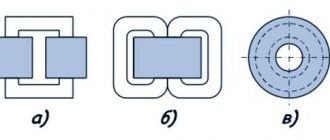
According to their structure, cores are divided into:
The rod core has the shape of the letter P. The windings are mounted on the rods, and the rods themselves are connected by a yoke. This design of the magnetic circuit makes it easy to inspect and repair the windings. Therefore, this type is typical for medium and powerful transformers.
W-shaped armor core The windings are located on the central rod. Armor transformers are more difficult to manufacture. And repairing the windings in them is not as easy as in rod ones.
The toroidal core has the shape of a ring with a rectangular cross-section. The windings are wound directly onto it. Therefore, this type of core is considered the most energy efficient.
a – rod core, b – armor core, c – toroidal core.
How to reduce losses in the magnetic core of a transformer?
In an operating transformer, the core is exposed to an alternating magnetic field. As a result, eddy currents arise around the core. Because of them, the magnetic circuit heats up - that is, part of the useful energy is wasted.
Losses due to magnetization reversal are affected by:
- the nature of the core material. The easier the metal is to magnetize, the easier it is to remagnetize it and the lower the losses in the transformer;
- magnetization reversal frequency;
- maximum value of magnetic induction.
To reduce losses, steel with pronounced magnetic properties is used to produce cores. Such material requires less energy for magnetization reversal.
In monolithic conductors, eddy currents acquire maximum values due to low resistance. Therefore, in order to reduce losses in a transformer, it is necessary to increase the resistance of the core material. Manufacturers of power transformers have found a way out: they assemble a magnetic core from metal sheets. Steel plates for the core are taken no more than 0.5 mm thick.
To truly reduce the eddy current resistance in the core, the metal plates need to be insulated. To achieve this, transformer manufacturers use varnish and scale. The interlayer prevents eddy currents from influencing the magnetic flux in the core. Therefore, losses are reduced.
Manufacturers assemble wafers in two ways:
- end-to-end - in this case the core itself is assembled, then the windings are placed on it and only after that everything is yoke-fastened into a single structure;
- interlacing (laminated cores) - when each next row of plates overlaps the joints on the previous one.
It is easier to install end-to-end magnetic circuits, but the level of losses in them is higher than that of laminated cores. Therefore, laminated transformers are in great demand.
Main properties and characteristics
The steel used for transformers is stainless, magnetic and has sufficient permeability. It is so popular in the production of electrical equipment due to the fact that it has high electromagnetic characteristics and loses a minimal amount of energy as a result of sterility.
Various elements for transformers and other electrical equipment are made from metal. It is also ideal for creating magnetic wires.
Transformer cores cannot do without this special type of steel because the material contributes to a higher resistivity. This allows less power to be lost from eddy currents. This problem usually affects the cores of electrical equipment. Thanks to its use, excessive heating of the core does not occur.
To reduce losses from eddy flows, reduce the thickness of the plate. Therefore, the steel thickness should be 0.5 mm at a frequency of 50 Hz. If the device operates at a higher frequency, then it is necessary to make a core from sheets of 0.1-0.2 mm.
Metal helps reduce magnetization reversal losses. This is another reason for the popularity of electrical steel for transformer core production.
Since losses and the process of cyclic magnetization reversal can be reduced by adding silicon to the metal, alloys with a high content of this element are called transformer steel. Thanks to the application, it was possible to reduce losses by a third. This also makes it possible to reduce the mass of the transformer by 10% and metal consumption by 20%.
Electromagnetic steel is used in almost all electromechanical products due to its unique properties.