How to check the armature winding?
The verification takes place in stages:
- Ring the paired terminals of the stator windings to the lamellas. ...
- Check the resistance between the armature body and the lamellas - ideally it tends to infinity.
- Ring the terminals to check the integrity of the winding.
- Check the condition of the circuit between the armature winding terminals and the stator housing.
Interesting materials:
What do you need to work as a Retoucher? What do you need for a maternity hospital list? What is needed to change your last name after a divorce? What is needed to change your last name in Belarus? What is needed to demolish an old house? What do you need to get into the riot police? What is needed to obtain Canadian citizenship? What does it take to become a surrogate mother? What do you need to add to the cream to make sour cream? What should you say 33 times after prayer?
for “How to test a pulse transformer”
- Willy
:V
Friends, tell me in what cases does an interturn short circuit occur in a pulse transformer?
Answer
Admin
:
V
There can be many reasons, the main ones can be identified: fluctuations in the mains voltage, which these step-down rectifier devices are not designed for; non-compliance with operating rules; connecting a load for which the devices are not designed.
Answer
:
V
In the last 20 years, instead of traditional buck-rectifier circuits based on a power transformer and a diode bridge, pulse units are built using a pulse voltage conversion circuit. Despite their high circuit reliability, they often fail
Answer
:
V
What is the difference between a pulse transformer and a regular one?
Answer
- Admin
:
V
The pulse transformer has specific design and operating principles. See the differences here
Answer
:
V
Good day! How to determine the windings of a pulse transformer?
Answer
:
V
The secondary windings have very few turns, but the primary winding has more resistance. Another sign is the “pigtail” - this is the middle of the secondary windings.
Answer
:
V
watch the video: Testing a pulse transformer
Answer
Basic information about transformers
To convert alternating voltage ratings, special electrical machines—transformers—are used.
A transformer is an electromagnetic device designed to convert alternating voltage and current of one magnitude into alternating current and voltage of another magnitude.
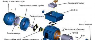
Device and principle of operation
It is used in all consumer power supply schemes, as well as for transmitting electricity over long distances. The transformer design is quite primitive:
- The ferromagnetic core is made of a ferromagnetic material and is called a magnetic core. Ferromagnets are substances that have spontaneous magnetization; the parameters (atoms have constant spin or orbital magnetic moments) vary greatly due to the magnetic field and temperature.
- Windings: primary (mains voltage is connected) and secondary (power supply to a consumer or group of consumers). There can be more than 2 secondary windings.
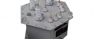
- Additional components are used for power transformers: coolers, gas relays, temperature indicators, moisture absorbers, current transformers, protection systems and continuous oil regeneration.
The principle of operation is based on the conductor being in an alternating electric field. When a conductor moves, for example, a solenoid (coil with a core), a voltage can be removed at its terminals, which depends directly proportionally to the number of turns. This approach is implemented in a transformer, but it is not the conductor that moves, but the electric field formed by alternating current. It moves along a magnetic circuit made of ferromagnet. Ferromagnetic is a special alloy ideal for the manufacture of transformers. Basic materials for cores:
- Electrical steel contains a large mass fraction of silicon (Si) and is combined under high temperature with carbon, the mass fraction of which is no more than 1%. Ferromagnetic properties are not clearly expressed, and eddy current losses (Foucault currents) occur. Losses increase directly proportionally with increasing frequency. To solve this problem, Si is added to carbon steel (E42, E43, E320, E330, E340, E350, E360). The abbreviation E42 stands for: E - electrical steel containing 4% - Si with 2% magnetic losses.
- Permalloy is a type of alloy and its constituent parts are nickel and iron. This species is characterized by a high value of magnetic permeability. Used in low-power transformers.
When current flows through the primary winding (I), a magnetic flux F is formed in its turns, which propagates along the magnetic circuit to winding II, as a result of which an EMF (electromotive force) is formed in it. The device can operate in 2 modes: load and idle.
Transformation coefficient and its calculation
Transformation ratio (k) is a very important characteristic. Thanks to it, you can identify malfunctions. The transformation ratio is a value showing the ratio of the number of turns of winding I to the number of turns of winding II. According to k, transformers are:
- Decreasing (k > 1).
- Raising (k
Preparation and testing
To check the operation of a pulse transformer, you can use both an analog and digital multimeter. The use of the second is preferable due to its ease of use. The essence of preparing a digital tester comes down to checking the battery and test leads. At the same time, the pointer-type device is additionally adjusted to this.
The analog device is configured by switching the operating mode to the area of measuring the minimum possible resistance. Afterwards, two wires are inserted into the tester sockets and short-circuited. Using a special construction handle, the position of the arrow is set opposite zero. If the arrow cannot be set to zero, then this indicates discharged batteries that will need to be replaced.
It's easier with a digital multimeter. Its design uses an analyzer that monitors the condition of the battery and, if its parameters deteriorate, displays a message on the tester screen indicating that it needs to be replaced.
When checking transformer parameters, two fundamentally different approaches are used. The first is to assess the serviceability directly in the circuit, and the second - autonomously from it. But it is important to understand that if the IT is not removed from the circuit, or at least a number of pins are not disconnected, then the measurement error can be very large. This is due to other radioelements that shunt the input and output of the device.
Procedure for identifying defects
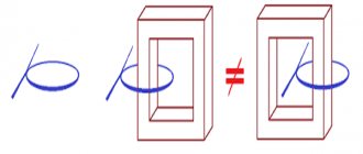
An important step in checking a transformer with a multimeter is identifying the windings. However, their direction does not play a significant role. This can be done using the markings on the device. Usually a certain code is indicated on the transformer.
In some cases, a diagram of the location of the windings or even their conclusions may be marked on the IT. If the transformer is installed in the device, then a circuit diagram or specification will help in finding the pinout. Also often the designations of the windings, namely the voltage and the common terminal, are signed on the PCB itself near the connectors to which the device is connected.
Once the conclusions have been determined, you can proceed directly to testing the transformer. The list of malfunctions that may occur in the device is limited to four points:
- core damage;
- burnt out contact;
- insulation breakdown leading to an interturn or frame short circuit;
- wire break.
The verification sequence is reduced to an initial external inspection of the transformer. It is carefully checked for blackening, chips, and odor. If no obvious damage is detected, then proceed to measurement with a multimeter.
Investigation for open circuit and short circuit
To check the integrity of the windings, it is best to use a digital tester, but you can also examine them using a pointer tester. In the first case, the diode testing mode is used, indicated on the multimeter by the symbol -|>| —))). To determine a break, test leads are connected to the digital device. One is inserted into the connectors marked V/Ω, and the second is inserted into COM. The roller switch is moved to the dialing area. The measuring probes are sequentially touched to each winding, red to one of its terminals, and black to the other. If it is intact, the multimeter will beep.
An analog tester performs the test in resistance measurement mode. To do this, the tester selects the smallest resistance measurement range. This can be implemented through buttons or a switch. The probes of the device, as in the case of a digital multimeter, touch the beginning and end of the winding. If it is damaged, the arrow will remain in place and will not deviate.
The same procedure is used to check for short circuits. A short circuit may occur due to an insulation breakdown. As a result, the winding resistance will decrease, which will lead to redistribution of the magnetic flux in the device. To carry out testing, the multimeter switches to resistance testing mode. By touching the windings with probes, they look at the result on a digital display or on a scale (arrow deflection). This result should not be less than 10 ohms.
To make sure that there is no short circuit on the magnetic circuit, touch the “hardware” of the transformer with one probe, and touch the second one sequentially to each winding. There should be no deviation of the arrow or appearance of a sound signal. It is worth noting that the interturn short circuit can only be measured with a tester in an approximate form, since the error of the device is quite high.
Voltage and current measurements
If a transformer is suspected of malfunctioning, testing can be carried out without completely disconnecting it from the circuit. This testing method is called direct, but is associated with the risk of electric shock. The essence of current measurement is to perform the following steps:
- one of the legs of the secondary winding is unsoldered from the circuit;
- the black wire is inserted into the COM socket of the multimeter, and the red wire is connected to the connector marked with the letter A;
- The device switch is moved to the position corresponding to the ACA zone.
- The probe connected to the red wire touches the free leg, and the black wire touches the place to which it was soldered.
When voltage is applied, if the transformer is operational, a current will begin to flow through it, the value of which can be seen on the tester screen. If IT has several secondary windings, then the current strength is checked on each of them.
The voltage measurement is as follows. The circuit with the transformer installed is connected to the power source, and then the tester switches to the ACV (alternating signal) region. The wire plugs are inserted into the V/Ω and COM sockets and touch the beginning and end of the winding. If the IT is normal, the result will be displayed on the screen.
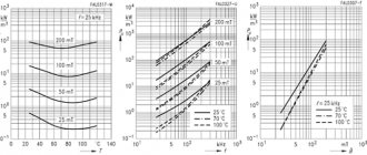
Removing characteristics
To be able to check a transformer with a multimeter using this method, its current-voltage characteristic is necessary. This graph shows the relationship between the potential difference at the terminals of the secondary windings and the current strength leading to their magnetization.
The essence of the method is as follows: the transformer is removed from the circuit, and pulses of different sizes are applied to its secondary winding using a generator. The power supplied to the coil must be sufficient to saturate the magnetic circuit. Each time the pulse changes, the current in the coil and the voltage at the output of the source are measured, and the magnetic circuit is demagnetized. To do this, after removing the voltage, the current in the winding increases in several approaches, after which it decreases to zero.
As the current-voltage characteristic is taken, its real characteristic is compared with the reference one. A decrease in its slope indicates the appearance of an interturn short circuit in the transformer. It is important to note that to plot the current-voltage characteristic it is necessary to use a multimeter with an electrodynamic head (pointer).
Thus, using a regular multimeter, you can with a high degree of probability determine the performance of IT , but for this it is best to perform a set of measurements. Although, to correctly interpret the result, you should understand the operating principle of the device and imagine what processes occur in it, but in principle, for successful measurement it is enough just to be able to switch the device to different modes.