Operating principle of capacitors
When a circuit is connected to an electrical source, electrical current begins to flow through the capacitor. At the beginning of the passage of current through the capacitor, its strength is at its maximum and the voltage is at its minimum. As the device accumulates charge, the current drops until it disappears completely, and the voltage increases.
During the process of charge accumulation, electrons accumulate on one plate and positive ions on the other. Charge does not flow between the plates due to the presence of a dielectric. This is how the device accumulates charge. This phenomenon is called the accumulation of electric charges, and the capacitor is called an electric field accumulator.
Capacitor design
The designs of modern capacitors are varied, but several typical options can be distinguished:
Batch design
Used in glass-enamel, ceramic and glass-ceramic capacitors. The packages are formed by alternating layers of plates and dielectric. The covers can be made of foil, or they can be layers on dielectric plates - sprayed or applied by burning.
Each stack capacitor has upper and lower plates that have contacts at the ends of the stack. Terminals are made of wire or tape strips. The package is pressed, sealed, and covered with protective enamel.
Tubular design
High-frequency capacitors can have this design. They are a ceramic tube with a wall thickness of 0.25 mm. A silver conductive layer is applied to its outer and inner sides by burning in. The outside of the part is treated with an insulating substance. The inner lining is brought out onto the outer layer to attach a flexible lead to it.
Disc design
This design, like the tubular one, is used in the manufacture of high-frequency capacitors.
The dielectric in disk capacitors is a ceramic disk. Silver plates are burned onto it, to which flexible leads are connected.
Cast sectional construction
It is used in monolithic multilayer ceramic capacitors used in modern equipment, including integrated circuits. A part with 2 grooves is made by casting ceramics. The grooves are filled with silver paste, which is secured using the implantation method. Flexible leads are soldered to the silver inserts.
Roll design
Characteristic of paper film low-frequency capacitors with high capacity. Paper tape and metal foil are rolled into a roll. In metal-paper capacitors, a metal layer up to 1 micron thick is applied to the paper tape.
Film capacitors
In this type of capacitor, the dielectric is a plastic film, for example, polyester (KT, MKT, MFT), polypropylene (KP, MKP, MFP) or polycarbonate (KC, MKC).
Electrodes can be deposited on this film (MKT, MKP, MKC) or made in the form of a separate metal foil, wound into a roll or pressed together with a dielectric film (KT, KP, KC). The modern material for capacitor film is polyphenylene sulfide (PPS).
General properties of film capacitors (for all types of dielectrics):
- work properly at high current;
- have high tensile strength;
- have a relatively small capacity;
- minimum leakage current;
- used in resonant circuits and RC snubbers.
Individual types of film differ:
- temperature properties (including the sign of the temperature coefficient of capacity, which is negative for polypropylene and polystyrene, and positive for polyester and polycarbonate)
- maximum operating temperature (from 125 °C for polyester and polycarbonate, up to 100 °C for polypropylene and 70 °C for polystyrene)
- resistance to electrical breakdown, and therefore the maximum voltage that can be applied to a certain film thickness without breakdown.
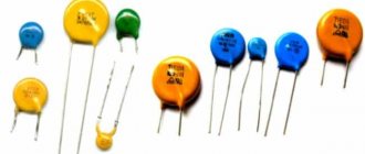
Ceramic capacitors
This type of capacitor is made in the form of a single plate or a stack of plates from a special ceramic material. Metal electrodes are sprayed onto the plates and connected to the terminals of the capacitor. The ceramic materials used can have very different properties.
The diversity includes, first of all, a wide range of relative electrical permeability values (up to tens of thousands), and this value is found only in ceramic materials.
Such a high permeability value makes it possible to produce ceramic capacitors (multilayer) of small sizes, the capacitance of which can compete with the capacitance of electrolytic capacitors, and at the same time work with any polarization and are characterized by less leakage.
Ceramic materials are characterized by a complex and nonlinear dependence of parameters on temperature, frequency, and voltage. Due to the small size of the case, this type of capacitor has a special marking.
Where are capacitors used?
Capacitors are used in almost all modern devices: subwoofers, electric motors, cars, pumps, power tools, air conditioners, refrigerators, mobile phones, etc.
Depending on the functions performed, they are divided into general purpose and highly specialized.
General purpose capacitors include low-voltage storage devices that are used in most types of electrical equipment.
Highly specialized ones include high-voltage, pulse, noise suppression, dosimetric and start-up capacitors.
Application
The main applications of capacitors are the following devices:
- Network ripple filters;
- Frequency filters;
- Ballast power supplies;
- Capacitor power supply;
- Snubbers;
- Distributor voltage multiplier;
- Charger for car batteries;
- Device for smooth starting of an electric motor (starting unit);
- Installation of capacitor welding.
In all these devices, the main purpose of the capacitor is to smooth out voltage surges. This is achieved thanks to the repeatedly repeating charge-discharge cycle of the drive.
What are capacitors for, areas of use of storage devices
Understanding what a capacitor is and why it is needed, what its operating principle is, is necessary not only for a specialist who repairs household and computer equipment, but also for an ordinary person who does not deal with radio electronics. Such knowledge will help you independently find a failed drive and replace it.
Behavior of a capacitor in DC and AC circuits
In DC circuits, a charged capacitor forms a gap that prevents the flow of current. If voltage is applied to the plates of a discharged part, current will flow. In this case, the capacitor will charge, the current will drop, and the voltage on the plates will increase. When the voltage on the plates and the power supply is equal, the current flow stops.
With constant voltage, the capacitor holds a charge when the power is on. After switching off, the charge is discharged through the loads present in the circuit.
A charged capacitor also does not allow alternating current to pass through. But during one period of the sinusoid, the storage device is charged and discharged twice, so the current is able to flow through the capacitor during its discharge period.
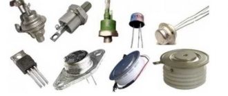
Types and classification of capacitors
Different types of capacitors are adapted to different operating conditions, are aimed at performing specific tasks and have various side effects.
The main feature by which a capacitor is classified is the type of dielectric. It is the dielectric material that determines many of the characteristics of a capacitor.
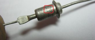
Electrolytic capacitors
In electrolytic capacitors, the anode is a metal plate, the dielectric is an oxide film, and the cathode is a solid, liquid or gel-like electrolyte. The presence of a gel-like electrolyte makes the device polar, meaning current can only flow through it in one direction. Representatives of this family are aluminum and tantalum capacitors.
Aluminum electrolytic capacitors have a capacity from 0.1 to several thousand microfarads. They are usually used at audio frequencies. The electrochemical cell is tightly packed, which provides high effective inductance, which prevents the use of aluminum storage devices at ultra-high frequencies.
In tantalum capacitors, the cathode is made of manganese dioxide. The combination of the significant surface area of the anode and the dielectric characteristics of tantalum oxide provides a high specific capacitance (capacitance per unit volume or mass of the dielectric). This means that tantalum capacitors are much more compact than aluminum capacitors of the same capacity.
Tantalum capacitors have their disadvantages. Devices of early generations are prone to failures and fires are possible. They can occur when too high an inrush current is applied, which changes the structural state of the dielectric. The fact is that tantalum oxide in an amorphous state is a good dielectric. When a large inrush current is applied, tantalum oxide changes from an amorphous state to a crystalline state and turns into a conductor. Crystalline tantalum oxide further increases the current strength, which leads to fire. Modern tantalum capacitors are produced using advanced technologies and practically do not fail, do not swell, and do not catch fire.
Film and metal film capacitors
Film capacitors have a dielectric layer of polymer film located between layers of metal foil.
Such devices have a small capacitance (from 100 pF to several μF), but can operate at high voltages - up to 1000 V.
There is a whole family of film capacitors, but all types are characterized by small capacitance and inductance. Due to their low inductance, these devices are used in high-frequency circuits.
The main differences between capacitors with different types of films:
- Capacitors with a dielectric in the form of a polypropylene film are used in circuits that place high demands on temperature and frequency stability. They are suitable for power supply systems, EMI suppression.
- Capacitors with a dielectric in the form of a polyester film are low cost and can withstand high temperatures when soldering. Frequency stability, compared to polypropylene types, is lower.
- Capacitors with a dielectric made of polycarbonate and polystyrene film, which were used in old circuits, are no longer relevant today.
Ceramic capacitors
Ceramic capacitors use ceramic plates as the dielectric.
Ceramic capacitors have a small capacitance - from one pF to several tens of microfarads.
Ceramics have a piezoelectric effect (the ability of a dielectric to polarize under mechanical stress), so some types of these capacitors have a microphonic effect. This is an undesirable phenomenon in which part of the electrical circuit picks up vibrations, like a microphone, which causes interference.
Paper and metal-paper capacitors
Paper, often oiled, is used as a dielectric in these capacitors. Devices with oiled paper are larger in size. Models with non-oiled paper are more compact, but they have a significant drawback - they increase energy losses under the influence of moisture, even in sealed packaging. Lately, these parts are rarely used.
More information about types and analogues of capacitors
Kinds
The main criteria used in classifying capacitors are their polarity, dielectric material, body shape, and the ability to change the capacitance.
Depending on the polarity, drives come in two types:
- Polar - electrolytic storage devices, one of the plates of which is the anode, the second is the cathode. For use only in an electrical circuit connected to a DC power source. Failure to observe the polarity when connecting such a drive can lead to its failure.
- Non-polar - drives that do not have a polarity for connecting the electrodes. Used in circuits powered by alternating current.
Depending on the dielectric material:
- Tantalum;
- Niobium;
- Ceramic;
- Polyethylene terephthalate;
- Polyamide (film type);
- Polypropylene.
Less common are old Soviet capacitors with a dielectric made of mica or oiled paper.
According to the shape of the case, the drive can be:
- Cylindrical;
- Flat;
- Spherical.
Depending on the possibility of changing the capacitance, capacitors are:
- Permanent storage devices are the most numerous and widespread type of storage devices with a constant capacity.
- Variables - the capacity of such devices is adjusted mechanically or by changing voltage and temperature.
- Post-construction - the capacity of such drives is adjusted before turning on the equipment in which they are installed.
Basic parameters of capacitors
Capacity
This indicator characterizes the capacitor's ability to accumulate electrical charge. The larger the area of the conductor plates and the smaller the thickness of the dielectric layer, the larger the capacitance. This characteristic also depends on the dielectric material. The device indicates the nominal capacity. The actual capacity, depending on operating conditions, may differ from the nominal capacity within significant limits. Standard options for nominal capacity range from units of picofarads to several thousand microfarads. Some models may have a capacity of several tens of farads.
Classic capacitors have a positive capacitance, that is, the greater the applied voltage, the greater the accumulated charge. But today, devices with unique properties, which scientists call “anti-capacitors,” are under development. They have negative capacitance, that is, as the voltage increases, their charge decreases, and vice versa. The introduction of such anti-capacitors into the electronics industry will speed up the operation of computers and reduce the risk of overheating.
What happens if you install a drive with a larger/smaller capacity than required? If we are talking about smoothing out voltage ripples in power supplies, then installing a capacitor with a capacitance exceeding the required value (within reasonable limits - up to 90% of the nominal value) in most cases improves the situation. Installing a capacitor with a smaller capacitance may degrade the performance of the circuit. In other cases, the possibility of installing a part with parameters different from the specified ones is determined specifically for each case.
Specific capacitance
The ratio of the nominal capacitance to the volume (or mass) of the dielectric. The thinner the dielectric layer, the higher the specific capacitance, but the lower its breakdown voltage.
Energy Density
This concept refers to electrolytic capacitors. The maximum density is typical for large capacitors, in which the mass of the housing is significantly lower than the mass of the plates and electrolyte.
Rated voltage
Its value is reflected on the housing and characterizes the voltage at which the capacitor operates during its service life with parameters fluctuating within specified limits. The operating voltage must not exceed the rated value. For many capacitors, the rated voltage decreases as the temperature increases.
Polarity
Polar capacitors are electrolytic capacitors that have positive and negative charges. On domestically produced devices, a “+” sign was usually placed at the positive electrode. On imported devices, a negative electrode is indicated, next to which there is a “-” sign. Such capacitors can perform their functions only if the voltage polarity is connected correctly. This fact is explained by the chemical features of the reaction of the electrolyte with the dielectric.
What happens if you reverse the polarity of a capacitor? Usually in this case the devices fail. This occurs due to the chemical destruction of the dielectric, which causes an increase in current strength, boiling of the electrolyte and, as a result, swelling of the housing and a possible explosion.
Most charge storage devices belong to the group of non-polar capacitors. These parts ensure correct operation no matter how the pins are connected to the circuit.
How are capacitors designated in electrical diagrams?
Capacitors in electrical diagrams are indicated by two vertical lines separated by a small space. The graphic image resembles those same two plates separated by an air dielectric.
For electrolytic capacitors, a “+” sign is placed near one of the lines (plates).
This is because electrolytic capacitors usually have a polarity that must be observed during installation.
Note that in some cases electrolytic non-polar capacitors are used.
The value of the capacitance of the capacitor is indicated next to it.
And if the capacitor is electrolytic, then so is the value of its operating voltage.
Entries of the form 1000 p (1000 pF) and 3.9 n (3.9 nF) mean 1000 picofarads and 3.9 nanofarads (or 3900 picofarads), respectively.
An entry of the form 1000uFx16V means a capacity of 1000 microfarads and an operating voltage of 16 Volts.
Opposite the negative electrode, a corresponding marking is applied to the capacitor body (sign “-”).
Parasitic parameters of capacitors
Capacitors, in addition to their main characteristics, have so-called “parasitic parameters” that distort the operating properties of the oscillating circuit. They must be taken into account when designing the circuit.
These parameters include their own resistance and inductance, which are divided into the following components:
- Electrical insulation resistance (r), which is determined by the formula: r = U/Iout, in which U is the power source voltage, Iout is the leakage current.
- Equivalent series resistance (ESR). This value depends on the electrical resistance of the material of the plates, leads, contacts between them, and losses in the dielectric layer. The ESR increases with increasing frequency of the current supplied to the storage device. In most cases, this characteristic is not important. The exception is electrolytic storage devices installed in the filters of switching power supplies.
- Equivalent series inductance - L. At low frequencies, this parameter, due to the self-inductance of the plates and leads, is not taken into account.
Parasitic parameters also include Vloss - an insignificant value expressed as a percentage, which shows how much the voltage drops immediately after the capacitor stops charging.
Designation of capacitors in the diagram
In the drawings, a capacitor with a constant capacitance is indicated by two parallel lines - plates. They are signed with the letter "C". Next to the letter they put the serial number of the element on the diagram and the capacitance value in pF or µF.
In variable capacitors, parallel lines are crossed out by a diagonal line with an arrow. Tuning models are indicated by two parallel lines crossed out by a diagonal line with a dash at the end. The designation of polar capacitors indicates a positively charged plate.
| Fixed capacitor |
| Polarized (polar) capacitor |
| Variable capacitor tuning capacitor |
| Varicap |
Features of connecting several capacitors in a circuit
The connection of several capacitors to each other can be series or parallel.
Sequential
A series connection allows you to apply more voltage to the plates than to a separate part. The voltage is distributed depending on the capacity of each drive. If the capacitances of the parts are equal, then the voltage is distributed equally.
The resulting capacitance in such a circuit is found by the formula:
Commun = 1/(1/С1+1/С2…+1/Сn)
If you carry out calculations, it will become clear that an increase in voltage in the circuit is achieved by a significant drop in capacitance. For example, if two 10 µF capacitors are connected in series in a circuit, the total capacitance will be only 5 µF.
Parallel
This is the most common method in practice to increase the total capacitance in the circuit. A parallel connection allows you to create one large capacitor with the total area of the conducting plates. The total capacity of the system is the sum of the capacities of the connected parts.
C total = C1+C2+…+Cn
The voltage on all elements will be the same.
Capacitor markings
The marking of a capacitor, regardless of its type, contains two mandatory parameters - capacitance and rated voltage. The most common digital marking indicates the resistance value. It uses three or four digits.
Briefly, the essence of the three-digit marking: the first two digits on the left indicate the capacitance value in picofarads. The rightmost number shows how many zeros should be added to the numbers on the left. The result is obtained in picofarads. Example: 154 = 15x104 pF. On foreign-made capacitors, pF are designated as mmf.
In a four-digit code, the capacitance in picofarads is indicated by the first three digits, and the fourth indicates the number of zeros to be added. For example: 2353=235x103 pF.
To designate the capacity, alphanumeric markings containing the letter R can also be used, which indicates the location of the decimal point. For example, 0R8=0.8 pF.
On the case, the voltage value is indicated by a number followed by the letters: V, WV (which means “operating voltage”). If there is no indication of the permissible voltage, then the capacitor can only be used in low-voltage circuits.
In addition to capacitance and voltage, other characteristics of the part may be indicated on the case:
- Dielectric material. B – paper, C – mica, K – ceramics.
- Degree of protection from external influences. G – hermetically sealed design, O – pressed housing.
- Design. M – monolith, B – barrel, D – disk, C – sectional version.
- Current mode. I – pulsed, U – universal, CH – direct current only, P – alternating/direct.
In what units is the capacitance of a capacitor measured?
The basic unit for measuring capacitance is the Farad (F, the old name is Farad).
But this is a very large value, so in practice its derivatives are used - picofarad (pF, picofarad), nanofarad (nF, nanofarad), microfarad (μF, microfarad).
One microfarad = 1,000 nanofarads = 1,000,000 picofarads.
Computer power supplies and motherboards use electrolytic capacitors with a capacity of several hundred or thousand microfarads.
Small-sized ceramic capacitors with a capacity of several hundred or thousand picofarads are also used there.
Ceramic capacitors are most often used in the form of SMD components.
How to check the performance of a capacitor
To check the capacitor for functionality, use a multimeter. Before checking the drive, it is necessary to determine which device is located in the circuit - polar (electrolytic) or non-polar.
Checking the polar capacitor
When checking a polar capacitor, it is necessary to observe the correct polarity of connecting the probes: the positive one must be pressed against the positive leg, the negative one against the minus leg. If you reverse the polarity, the capacitor will fail.
After desoldering the parts, it is placed in free space. The multimeter is switched on to the resistance measurement mode (“diagnosis”).
Use probes to touch the terminals of the device, observing polarity. The correct situation is when the first value appears on the display and begins to gradually increase. The maximum value that must be achieved for a working device is 1. If you just touched the leads with the probes and the number 1 immediately appears on the screen, it means the device is faulty. The appearance of “0” on the screen means that a short circuit has occurred inside the part.
Checking a non-polar capacitor
In this case, the check is extremely simple. The measurement range is set to 2 MOhm. The probes are connected to the capacitor terminals in any order. The resulting value must exceed two. If the display shows a value less than 2 MOhm, then the part is faulty.
What is a capacitor?
A capacitor is a part with two terminals (two-terminal network) that allows you to store energy.
A capacitor is characterized by a quantity called capacity.
The larger the capacitance of the capacitor, the more energy it can accumulate and the (roughly speaking) larger its dimensions.
A capacitor can not only store energy, but also release it.
It is in this mode that it most often works.
A capacitor, unlike a transistor, is a passive component, i.e. there is it cannot generate or amplify a signal.
How to charge and discharge a capacitor
To charge the drive, it is connected to a DC source. Charging stops when the power source voltage is equal to the voltage on the plates.
Discharging a capacitor may be necessary to safely disassemble household appliances and electronic devices. Electronic device storage devices are discharged using a conventional dielectric screwdriver. To discharge large storage devices that are installed in household appliances, it is necessary to assemble a special discharge device.
Story
The prototype of the modern capacitor was constructed in 1745 simultaneously by two scientists: the Dutch physicist Pieter van Musschenbroek and the German Lutheran cleric Ewald Jürgen von Kleist. The first called his invention the “Leyden jar”, the second – a medical jar. The similarity in the names was not accidental - the device, both German and Dutch, was a glass jar with two tin plates located on its outer and inner surfaces, with a dielectric plug inserted into the neck, which was pierced by a metal rod with a chain. Such a device was charged from an electrophore machine, which was very popular in those days. The charge accumulated on the plates was small - no more than 1 microcoulomb.
Invented in 1745, “banks” remained virtually unchanged over the next 200 years. Only in the mid-50s of the 20th century, during the active development of the production of various radio components, the first storage devices of relatively small sizes began to be produced. At the same time, they began to be used in various household appliances, electric tools, and later – computers.
For your information. Modern radio components of this type have a wide variety of shapes, sizes and characteristics: from the largest and most powerful ionistors to small drives used in computer printed circuit boards and in household appliance controllers.
"Leyden jar" and modern charge storage