General provisions
Efficiency is defined as the ratio of useful, or output, power P2 to consumed power P1:
| (1) |
or as a percentage
| (2) |
Modern electric machines have a high efficiency factor (efficiency). Thus, for DC machines with a power of 10 kW, the efficiency is 83 - 87%, with a power of 100 kW - 88 - 93% and with a power of 1000 kW - 92 - 96%. Only small machines have relatively low efficiency; for example, a 10 W DC motor has an efficiency of 30 - 40%.
| Figure 1. Dependence of the efficiency of an electric machine on the load |
The efficiency curve of an electric machine η = f(P2) first increases rapidly with increasing load, then the efficiency reaches its maximum value (usually at a load close to the rated load) and decreases at high loads (Figure 1) . The latter is explained by the fact that certain types of losses (electrical Ia2ra and additional) grow faster than the useful power.
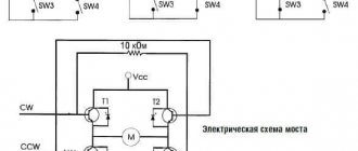
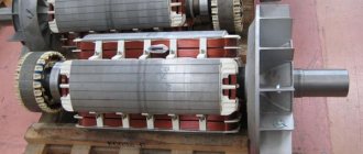
Switched reluctance motors
A switched reluctance motor (SRM) creates torque by attracting the magnetic fields of the rotor teeth to the magnetic field of the stator. Switched reluctance motors (WRM) have a relatively small number of stator winding poles. The rotor has a toothed profile, which simplifies its design and improves the generated magnetic field, unlike reluctance synchronous machines. Unlike synchronous reluctance motors (SRM), WRMs use pulsed DC excitation, which requires a special converter for their operation.
To maintain the magnetic field in the VRM, excitation currents are required, which reduces the power density compared to electric machines with permanent magnets (PM). However, they still have smaller overall dimensions than conventional ADs.
The main advantage of switched reluctance machines is that the magnetic field weakens naturally when the excitation current decreases. This property gives them a great advantage in the control range at speeds above the nominal (the range of stable operation can reach 10:1). High efficiency is present in such machines when operating at high speeds and with low loads. Also, VRDs are capable of providing surprisingly constant efficiency over a fairly wide control range.
Switched reluctance machines also have fairly good fault tolerance. Without permanent magnets, these machines do not generate uncontrolled current and torque during malfunctions, and the independence of the VRM phases allows them to operate with a reduced load, but with increased torque ripples when one of the phases fails. This property can be useful if designers want increased reliability of the system being developed.
The simple design of the VRD makes it durable and inexpensive to manufacture. No expensive materials are used in its assembly, and the non-alloy steel rotor is excellent for harsh climate conditions and high rotation speeds.
A VRD has a power factor lower than PM or IM, but its converter does not need to create a sinusoidal output voltage for the machine to operate efficiently; accordingly, such inverters have lower switching frequencies. As a result, lower losses in the inverter.
The main disadvantages of switched reluctance machines are the presence of acoustic noise and vibration. But these shortcomings can be combated quite well by more carefully designing the mechanical part of the machine, improving electronic control, and also mechanically combining the engine and the working body.
VFDs are well suited for a wide range of applications and are increasingly used for processing heavy-duty materials due to their high overload capacity and wide speed control range. Their high overload capacity makes them increasingly attractive for use as traction electric drives for modern electric vehicles. Also, VFDs are widely used in electrical appliances.
Direct and indirect methods for determining efficiency
The direct method of determining efficiency from the experimental values of P1 and P2 according to formula (1) can give significant inaccuracy, since, firstly, P1 and P2 are close in value and, secondly, their experimental determination is associated with errors . The greatest difficulties and errors are caused by measuring mechanical power.
If, for example, the true power values P1 = 1000 kW and P2 = 950 kW can be determined with an accuracy of 2%, then instead of the true value of efficiency.
η = 950/1000 = 0.95
available
or
Therefore, GOST 25941-83, “Rotating electric machines. Methods for determining losses and efficiency”, prescribes for machines with η% ≥ 85% an indirect method for determining efficiency, in which the amount of losses pΣ is determined from experimental data.
Substituting P2 = P1 - pΣ into formula (1), we obtain
| (3) |
Applying the substitution P1 = P2 + pΣ here, we obtain another form of the formula:
| (4) |
Since it is more convenient and accurate to measure electrical power (for engines P1 and for generators P2), formula (3) is more suitable for engines and formula (4) for generators. Methods for the experimental determination of individual losses and the sum of losses pΣ are described in standards for electrical machines and in manuals for testing and researching electrical machines. Even if pΣ is determined with significantly less accuracy than P1 or P2, when using formulas (3) and (4) instead of expression (1), significantly more accurate results are obtained.
Permanent magnet motors
Permanent magnet motors (PMMS) produce torque through the interaction of stator currents with permanent magnets inside or outside the rotor. Electric motors with surface magnets are low-power and are used in IT equipment, office equipment, and automobile transport. Integrated magnet motors (IPMs) are common in high-power machines used in industrial applications.
Permanent magnet (PM) motors can use concentrated (short pitch) windings if torque ripple is not critical, but distributed windings are the norm in PMs.
Since PMMS do not have mechanical commutators, converters play an important role in the winding current control process.
Unlike other types of brushless electric motors, PMMS do not require excitation current to maintain rotor flux. Consequently, they are capable of delivering maximum torque per unit volume and may be the best choice when weight and size requirements are at the forefront.
The greatest disadvantages of such machines include their very high cost. High-performance permanent magnet electric machines use materials such as neodymium and dysprosium. These materials are classified as rare earths and are mined in geopolitically unstable countries, which leads to high and unstable prices.
Also, permanent magnets add performance when working at low speeds, but are an “Achilles heel” when working at high speeds. For example, as the speed of a machine with permanent magnets increases, its EMF will also increase, gradually approaching the supply voltage of the inverter, while it is not possible to reduce the flux of the machine. Typically, the rated speed is the maximum for a PM with a surface magnetic design at the rated supply voltage.
At speeds above the rated speed, for electric motors with permanent magnets of the IPM type, active field suppression is used, which is achieved by manipulating the stator current using a converter. The speed range over which the motor can operate reliably is limited by approximately 4:1.
The need for field weakening depending on speed leads to losses independent of torque. This reduces efficiency at high speeds, and especially at light loads. This effect is most relevant when using PM as a traction automobile electric drive, where high speed on the highway inevitably entails the need to weaken the magnetic field. Developers often advocate the use of permanent magnet motors as traction electric drives for electric vehicles, but their effectiveness when working in this system is quite questionable, especially after calculations associated with real driving cycles. Some electric vehicle manufacturers have made the transition from PM to asynchronous electric motors as traction motors.
Also, significant disadvantages of electric motors with permanent magnets include their difficulty in controllability under fault conditions due to their inherent back-EMF. Current will flow in the windings, even when the converter is turned off, as long as the machine is rotating. This can lead to overheating and other unpleasant consequences. Loss of control over a weakened magnetic field, such as during a power outage, can lead to uncontrolled generation of electrical energy and, as a result, a dangerous increase in voltage.
Operating temperatures are another not the strongest side of PM, except for machines made of samarium-cobalt. Also, large inrush currents of the inverter can lead to demagnetization.
The maximum speed of PMMS is limited by the mechanical strength of the magnets. If the PM is damaged, its repair is usually carried out at the manufacturer, since removing and safely processing the rotor is practically impossible under normal conditions. And finally, recycling. Yes, this is also a bit of a hassle once the machine reaches the end of its life, but the presence of rare earth materials in this machine should make this process easier in the near future.
Despite the disadvantages listed above, permanent magnet motors are unsurpassed in terms of low-speed, small-sized mechanisms and devices.
Three main types of products according to the operating mode of the electric motor
The three main types of products according to the operating mode of the electric motor are products with constant speed, variable speed and rotor position control (or torque control). Different industrial automation products require different modes, and the set of questions that must be answered when choosing an electric motor may also vary (Fig. 2).
Rice. 2. AC induction motors are often chosen for industrial machines with rotary motion of the working body
For example, if the required maximum rotor speed is less than the rated speed, a gearbox may be needed. Perhaps for this purpose it will be possible to select a more compact electric motor, the rotor speed of which will provide higher efficiency. There is a lot of information online about how to size an electric motor, but users need to take other factors into account. To calculate the moment of inertia of the load, torque and rotor speed, it is necessary to know such parameters as the total mass and size (radius) of the load, as well as the coefficient of friction, gearbox losses and the operating cycle of the machine. In addition, to avoid overheating of the electric motor, it is necessary to take into account load changes, acceleration or deceleration rates and the duty cycle of the product.
Having decided on the type and size of the electric motor, the user also needs to take into account the influence of external factors and choose a design - for example, open or enclosed in a stainless steel casing for operation in a humid environment.
How to find out the power output
Motors are supposed to do some kind of work, and there are two important values that determine how powerful it is. This is the speed and turning force of the engine. The mechanical power output of the motor can be calculated using the following formula:
Pout = τ * ω
where Pout is the output power measured in watts (W);
τ is the moment of force, measured in Newton meters (N • m);
ω is the angular velocity measured in radians per second (rad/s).
It's easy to calculate the angular velocity if you know the engine speed in rpm:
ω = rpm * 2 * P / 60
where ω is angular velocity (rad/s);
rpm - rotation speed in revolutions per minute;
P is a mathematical constant (3.14);
60 is the number of seconds in a minute.
If the motor is 100% efficient, all electrical energy is converted into mechanical energy. However, such engines do not exist. Even precision small industrial motors have a maximum efficiency of 50-60%.
Measuring engine torque is a difficult task. This requires special expensive equipment. But it is possible to do this yourself with special information and formulas.
Choosing an electric motor: three questions
Even after all these decisions have been made, the user still needs to answer the following three questions before making a final choice.
Is constant rotor speed required?
In products with a constant rotor speed, the electric motor often operates at an approximately set frequency, and the acceleration and braking characteristics play virtually no role. In this case, relay control powered directly from the network is usually used. Control circuits often consist of a branch circuit with a fuse and contactor, a starting overload protection device, and a manual motor controller or soft starter.
For products with a constant rotor speed, AC and DC electric motors are suitable. DC motors provide rated torque at zero speed; this type of electric motors is very popular. AC motors are also a good choice as they have a high power factor and are low maintenance. A high performance servo motor or stepper motor would be overkill for a simple product.
Is variable rotor speed required?
Variable speed products typically require low-accuracy changes in linear speed and rotational speed, as well as well-defined acceleration and acceleration characteristics. Reducing rotor speed in products such as fans and centrifugal pumps often improves efficiency by matching power to load rather than operating at maximum speed with proportional control or damping. This is important for conveyor systems such as bottling lines.
Electric motors of both alternating and direct current with drives of the appropriate type operate effectively in products with variable rotor speed. For a long time, DC motor drive has been the only option for variable speed products, and the components for this combination are well established and time-tested. Even now, DC motors are widely used in low-power (less than 1 HP) products of this type, and are also useful in products with low rotor speed, as they provide rated torque at low speed and constant torque over a wide range frequency
A weak point of DC motors can be maintenance, as many of them use brushes for commutation, which wear out over time from contact with moving parts. Brushless DC motors are free from this drawback, but are more expensive to purchase, and their range is narrower.
Asynchronous AC motors are also freed from this problem, and together with a variable-frequency drive (Fig. 3), they make it possible to obtain higher efficiency in products with a power of more than 1 hp. pp., such as fans and pumps. Some types of actuators provide position feedback. If the nature of the product requires it, you can add a displacement sensor to the electric motor and select a drive that uses the signal from this sensor for feedback. This configuration can provide the same rotor speed control as a servo motor.
Rice. 3. The combination of DC motor and variable frequency drive is widely used to improve efficiency, and works effectively in a variety of variable speed rotor products .
Is rotor position control required?
Control of the position of the electric motor rotor with a small error is ensured by continuously checking its position during rotation. Products that require, for example, position control of a linear actuator can use a stepper motor with or without feedback, or a servomotor with built-in feedback.
A stepper motor is designed to move to a specified position at a moderate speed and then maintain that position. An open-loop stepper motor provides very precise control of rotor position if sized correctly, and will move a precise number of steps (unless it encounters a load change beyond its capabilities).
As the required speed and dynamic loads increase, the open-loop stepper drive may no longer provide the required system performance, and then a closed-loop stepper drive or servo drive will be needed.
The feedback system provides precise high-speed movement along a given profile and regulation of the rotor position. The servo motor provides greater torque at high speeds compared to a stepper motor, and also works more efficiently in products characterized by high dynamic loads or complex movements.
For fast and/or abrupt movement with low position overshoot, the moment of inertia of the load must be matched as closely as possible to the moment of inertia of the servomotor. Mismatch ratios of up to 10:1 are acceptable in some applications, but 1:1 matching is optimal.
Reducing the rotation speed through a gearbox is the best way to solve the problem of mismatch of moments of inertia, since the moment of inertia of the load is inversely proportional to the square of the gearbox ratio. In this case, the calculations must take into account the moment of inertia of the gearbox.