7.1. OPERATING PRINCIPLE AND DESIGN
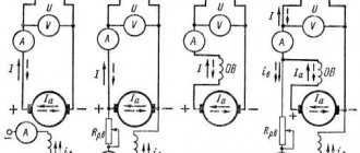
Two fixed poles N and S create magnetic flux. A steel core in the form of a cylinder is placed in the space between the poles (Fig. 7.1.1).
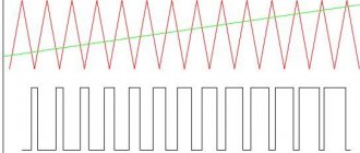
A coil of copper wire abcd is placed on the outer surface of the cylinder, insulated from the core. Its ends are connected to two rings, on which brushes 1 and 2 are placed. A load zn is connected to the brushes. If you rotate the core with a frequency n in the direction indicated in the figure, then the turn abcd, rotating, will intersect the magnetic lines of force, and an emf will be induced at its ends. And if a load zn is connected to the coil, then current will flow. The direction of the current is determined by the “right hand” rule. From the figure it can be seen that the direction of the current will be from points b to a and from d to c. Accordingly, in the external circuit, the current flows from brush 1 to brush 2. We denote brush 1, from which the current is diverted to the external circuit, (+), and brush 2, through which the current returns to the machine, we denote (-). When the coil is rotated 180°, the conductors ab and cd change places, the sign of the potential on brushes 1 and 2 changes, and the current in the external circuit changes in the opposite direction. Thus, an alternating sinusoidal current flows in the external circuit (Fig. 7.1.2).
To rectify alternating current, it is necessary to use a collector in the machine (Fig. 7.1.3).
In the simplest case, these are two half rings and the ends of the turns abcd are soldered to them. Half rings insulate from each other and from the shaft. When rotating in coil abcd, an alternating EMF still arises in it, but under each brush there will be an EMF of only one sign: the upper brush will always have (+), and the lower brush will always have (-). The current curve in the external circuit will have a different shape (Fig. 7.1.4).
The graph shows that the lower half-wave is replaced by the upper one. If you use not one turn, but two and connect their ends to the collector plates, of which there are now 4, then the rectified current curve will be different. If there are several turns, the rectified voltage curve will be smoother (Fig. 7.1.5).
A DC machine is structurally composed of a stationary part - the stator and a rotating part - the rotor. The stator has a frame, on the inner surface of which magnetic poles with windings are attached (Fig. 7.1.6).
The rotor of a machine is often called an armature. It consists of a shaft, a cylindrical core, a winding and a collector (Fig. 7.1.7).
The magnetic poles and the armature core are made from separate sheets of electrical steel. The sheets are coated with insulated paper or varnish to reduce hysteresis and eddy current losses. The collector is made of copper plates having a complex shape (Fig. 7.1.8). The plates are insulated from each other with a special heat-resistant gasket. The same insulation is found between the commutator and the motor shaft. A set of collector plates forms a cylinder-collector.
Adjacent to the outer surface of the commutator are current-collecting brushes, which are made of compressed copper and carbon powder. The brush is placed in a metal cage and pressed against the commutator by springs (Fig. 7.1.9).
7.2. METHODS OF EXCITING DC MACHINES
Excitation is a concept related to the creation of the main magnetic field of a machine. In machines with electromagnetic excitation, the main field is created by the field windings. There are designs in which the excitation is created by permanent magnets placed on the stator. There are four circuits for connecting stator windings: with independent, parallel, series and mixed excitation (Fig. 7.2.1).
Images under points b, c, d in Fig. 7.2.1 are called self-excited circuits. The process of self-excitation occurs due to the residual magnetization of the poles and frame. When the armature rotates in this small magnetic field (FOST = 0.02 0.03 FO), an EMF is induced - EOST. Since the field winding is connected through brushes to the armature, current will flow in it. This current will strengthen the magnetic field of the poles and lead to an increase in the armature EMF. A large EMF will again increase the excitation current and the magnetic flux will increase until the machine is completely magnetized.
Behavior of an electric motor when loads change
The mechanical characteristic shows the stability of the electric motor over a wide range of load changes, describing the dependence of the torque created by the electric motor on the operating speed of the shaft.
The traction characteristics of the mechanism of this type make it possible to maintain the magnitude of the torque with significant changes in the number of shaft revolutions. Typically, the traction parameters of the unit should ensure a decrease in this parameter by no more than 5%. A simple study demonstrates that the inhibitory parameters turn out to be similar due to the reversibility of the processes. These provisions also apply to the case of mixed excitation.
In other words, such an electric motor is characterized by a rigid characteristic. This nature of work is considered an important advantage of the unit of this type.
7.3. ARCH WINDINGS OF DC MACHINE
To operate a DC machine, you need two windings; field windings and armature windings. The first, as is known, serves to create the main magnetic flux in the machine, and in the second, energy is converted. The armature winding is a closed system of conductors laid in grooves. An element of the armature winding is a section, which can be one or many turns. The section consists of active sides and frontal parts. When the armature rotates, an emf is induced in each of the active sides, the value of which is equal to:
those. it depends on the magnetic induction of the poles of the HRV, the length of the conductor L and the speed of its movement V. In a real machine, be it a generator or a motor, all conductors of the armature winding participate in inducing the EMF. The value of the total EMF:
where n is the speed of rotation of the armature (rotor), rpm; F is the magnetic flux of the poles; Ce is a constant coefficient depending on the number of turns in the section. The armature winding can be loop or wave. The loop winding, if depicted in expanded form, has the following form (Fig. 7.3.1):
The distance between the active sides of one section is called the first winding pitch - y1. The distance between the beginning of the second section and the end of the first is called the second winding pitch - y2. The distance between the beginnings of sections following each other is called the resulting step - y. The winding pitches are determined by the number of slots. The distance between the collector plates, where the beginning and end belonging to the same section are soldered, is called the step along the collector - uk. In a loop winding uk = 1. The step uk is determined by the number of collector plates. The unfolded wave winding looks like: (Fig. 7.3.2).
The shape of the wave winding is different from the loop winding and, therefore, there will be a different connection of sections. However, the steps of the wave winding have a common definition with the loop winding. The step along the collector here is significantly greater than unity (uk >> 1).
MPT classification
In electrical engineering and the theory of electrical machines, it is customary to divide MMTs into devices with explicit and implicit excitation poles, with a cylindrical or polyhedral frame, with excitation by direct current or permanent magnets, with a mechanical commutator-collector on an armature or contactless. The purpose of DC machines divides them into general industrial and specialized. Among the latter we can name, for example, traction motorized motor vehicles used in rail transport. Metallurgical DC motors are also distinguished, especially motors for rolling mills, etc.
As is known, the windings of DC machines are divided into field windings (OB) and armature windings (OA). The former are used to excite the magnetic field of the device, and the latter are used to take power from the supply network in engine mode or to power an electrical load in generator mode. There are also windings of additional poles used to facilitate the switching process.
DC electrical machines, whether they are generators or motors, can be classified on the basis of the wiring diagrams of their field and armature windings. They can form a single electrical circuit or have no electrical connection at all (independent excitation). This classification principle divides MAT into two main types. You will understand their further classification from the diagram below.
7.4. EMF AND ELECTROMAGNETIC TORQUE OF DC GENERATOR
As already noted, the EMF induced in the winding of the rotating armature of the generator is proportional to the magnetic flux of the poles and the frequency of its rotation:
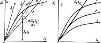
The magnetic flux in the generator, as is known, is created by the excitation current Iв. If you rotate the armature with a constant frequency n and continuously measure the output emf E, then you can plot a graph E = f (Iв) (Fig. 7.4.1).
This dependence is called the idle speed characteristic.
It is built for a mode when the generator has no external load, i.e. running idle. If you connect a load to the generator, the voltage at its terminals will be less than E by the value of the voltage drop in the armature circuit:
Here: U is the voltage at the terminals; E - EMF in idle mode; IА - armature current; RI is the resistance in the armature circuit. The voltage drop in the armature circuit usually does not exceed 2-8% of the generator's emf. The decrease in voltage at the generator output is associated with demagnetization of the machine by the magnetic field of the armature, as well as a drop in voltage in its windings. In every direct current machine, there is an interaction between the armature current IА and the magnetic flux F. As a result, an electromagnetic force acts on each conductor of the armature winding:
where B is magnetic induction, IА is the current in the armature winding, L is the length of the armature. The direction of this force is determined by the left-hand rule. Let us substitute here the average value of the magnetic induction of the HRV and the magnitude of the current in each conductor of the armature winding I = IА / 2 a. We get
Electromagnetic torque acting on the machine armature, with the number of winding conductors N:
where is a constant value for a given machine; d—anchor diameter; p—number of pole pairs; N is the number of conductors of the armature winding; a is the number of pairs of parallel branches. When the machine operates in generator mode, the electromagnetic torque acts against the rotation of the armature, i.e. is inhibitory. To drive a generator, an electric motor requires power, which must cover all losses in the generator:
where P is the useful electrical power of the generator; DРЯ - losses in the armature winding; DРВ - losses in the excitation winding; DРМ - losses due to magnetization of the machine; DРМЭХ - mechanical losses associated with friction of rotating parts.
The efficiency of the generator is determined by the ratio:
Modern DC generators have an efficiency of 90-92%.
Operating principle in generator mode
According to the original interpretation of the phenomenon of electromagnetic induction in a moving conductor, given by Faraday, when it crosses the magnetic field lines while moving, an EMF is induced in it. Following this principle, it is possible to explain the reason for the induction of EMF in the active conductors (those laid in the slots) of the MPT armature winding. Indeed, they move under the main poles, crossing the field lines. Since the latter are continuous, each armature conductor, regardless of whether it is located on its surface (as was the case in the first MPT designs) or in the grooves, passing under the pole, will intersect all the field lines emanating from its tip. The direction of action of the emf induced in a conductor can be determined by applying the right-hand rule, which is illustrated in the figure below.
The slot conductors of the armature are included in pairs as part of the turns of the coils of its winding. The sum of the emf of the turns gives the emf of the coil. Fixed brushes divide the entire armature winding into several (at least two) parallel branches. The sum of the EMF of all coils included in the parallel branch gives the EMF of the entire armature winding of the MPT. Thus, the principle of operation of DC machines when operating as a generator can be formulated as follows: the armature of the excited machine is rotated by the drive motor, an EMF is induced in its winding, which causes the flow of DC armature current in a closed electrical circuit, including the winding, commutator, brushes and external network with the load.
In the presence of armature current, a braking electromagnetic torque begins to act on it. It creates a load for the drive motor. The greater the electrical power of the generator load, the more its armature is braked and the higher the load of the drive motor. Moreover, according to the law of conservation of energy, the latter consumes so much fuel to set the generator armature into rotation that the chemical energy released during its combustion, minus the energy losses in the engine and generator, would be equal to the energy taken by the electrical load from the DC machine.
7.5. DC MOTOR
According to the principle of reversibility, a DC machine can operate both as a generator and as a motor. The EMF equation for the motor is based on Kirchhoff’s 2nd law, taking into account the direction of the EMF:
where
Armature circuit current:
In accordance with the formula Ea = Ce Ф n, the rotation speed is determined by the expression:
Substituting the value of E from the equation U = E - IЯ RЯ, we get:
those. The engine speed is directly proportional to the applied voltage and inversely proportional to the excitation magnetic flux. From this formula it can be seen that there are possible ways to regulate the rotation speed of a DC motor: 1. By changing the network voltage U. By adjusting the supplied voltage U, you can change the rotation speed. 2. By including additional resistance in the armature circuit (R'Я = RЯ + RADOB). By changing the resistance RDOB, the rotation speed is changed. 3. By changing the magnetic flux F. Machines with permanent magnets are not regulated. Machines with electromagnets make it possible to regulate the flow Ф by changing the excitation current IB. In Fig. 7.5.1. shows a diagram of connecting a DC motor to the network.
According to the law of electromagnetic induction, when current passes through the armature winding, its conductors interact with the magnetic field of the poles. Each conductor of the winding will be subject to an electromagnetic force Rem = BCPLI, proportional to the magnetic induction of the poles B, the length of the conductor L and the current I flowing through the conductor. The direction of this force is determined by the right hand rule. Without repeating the reasoning carried out for the DC generator, we write down the expression for the torque:
M=CMФ IЯ
where CM is the proportionality coefficient. The torque of motors with independent and parallel excitation can either increase or decrease with increasing load, since with increasing current consumption I and pole demagnetization, magnetic flux F decreases.
Series-wound motors have different characteristics from the above motors. From the diagram shown in Fig. 7.2.1c, it is clear that the magnetic flux in the machine is created by an excitation winding connected in series with the armature winding. Therefore, IB = IА and the expression for the torque will be:
The last formula shows that the greater the load on the engine, the greater the torque will be. This circumstance makes a motor with sequential excitation indispensable in electric transport (trams, trolleybuses, etc.). Reversing or changing the direction of rotation of DC motors can be accomplished by changing the polarity of the current either in the armature winding or in the field winding.
On the physical mechanism for inducing EMF in the conductors of the armature winding of the MPT
It should be noted that theoretical physicists do not like the above (and popular in technical literature) physical mechanism for inducing EMF, since magnetic field lines are just a speculative image invented by Faraday to describe it. There is no evidence of their actual existence as real physical objects.
An alternative mechanism for inducing EMF in the moving slot conductor of the MPT armature winding is the effect on the electrons inside it of the Lorentz force, proportional to the magnetic induction at the location of the conductor. However, here too there is a contradiction, namely that inside the armature slots the magnetic induction is vanishingly small, but this does not affect the magnitude of the EMF of the conductors. Therefore, instead of induction in the groove, induction in the air gap is substituted into the formula, which, of course, is incorrect, but gives a result close to that observed in practice.
The way out of this conflict is to transition to describing the magnetic field not using the magnetic induction vector, but using the vector magnetic potential. An active supporter of this approach was the outstanding Russian electrical engineer K. M. Polivanov. You can get acquainted with this problem in more detail in the author’s works.
7.6. ELECTRICAL MACHINE AMPLIFIERS
The simplest power amplifier is a conventional DC generator with independent excitation. The gain of the machine is determined by the ratio of the current flowing in the armature winding to the excitation current:
In this design, the gain is about 15 - 30. The amplification capacity of the generator can be increased if you use a cascade circuit for connecting generators. In this case, the excitation winding of the second is connected from the output of the first generator, and the output from the second generator will exceed the power of the input of the first by 1000 or more times. The cascade scheme is rarely used due to its bulkiness and high cost. More often they use so-called electric machine amplifiers (EMA). The electrical circuit of the EMU is shown in Fig. 7.6.1.
Structurally, the electric machine amplifier is a DC commutator machine with independent excitation, having two sets of brushes (longitudinal 1-1′ and transverse 2-2′). The current flowing through the excitation winding Ib creates a longitudinal magnetic flux Фd, directed along the axis of the poles of the machine. When the armature rotates, an emf E2 = C n Фd appears on the transverse brushes 2-2′. Since they are short-circuited, a large current I2 appears in the armature winding. This current creates in the armature winding a strong transverse magnetic field of the armature reaction Фq, stationary in space and directed along the axis of the brushes 2-2′. Under the influence of magnetic flux Фq in the armature winding between brushes 1-1′, an emf E1 = C n Фq >>E2 arises, since Фq >>Фd. When a load Rн is connected to brushes 1-1′, a current Iа will flow in the circuit, tens of thousands of times greater than the current Iв. Electric machine amplifiers are used to automatically control powerful electric motors.
Generator circuit with built-in voltage regulator
In this case, the voltage regulator is mounted in a single unit with the brush unit, and installed on the generator.
Generators 58.3701 were made according to this scheme for the Moskvich car and all generators for UAZ, ZIL, GAZ cars of the 80s - 90s.
All three circuits are circuits with the excitation winding powered from the generator output. The initial excitation comes from the battery, and after starting, the excitation current is taken from the output of the generator, that is, from the same point.
Disadvantage: Circuits powering the excitation winding from the generator output
.
The battery is always connected to the positive terminal of the generator, this is necessary so that the generator and the battery can work as sources, replacing each other - the engine does not work - the source is the battery, the engine has started - the source is the generator, and everything works from it, and the battery is charged. When the generator is not running, the battery directly connected to it cannot be uselessly discharged through the diode bridge because the diode bridge does not pass current in the opposite direction, but, through the field winding in the rotor, the battery can be discharged
.
If the engine does not start and the generator does not work, but the ignition remains on
, then the rotor current comes from the battery (which is 3 - 5 Amperes) and discharges it. For various reasons, such situations sometimes arise and then, after several hours of leaving the ignition on, the engine will not start. Such schemes, in which the rotor is powered from the generator output and therefore connected directly to the battery, can lead to unexpected discharge of the battery.
7.7. SINGLE-ARM CONVERTERS
To convert alternating current into direct current, as is known, rectifiers are used. Conversion of direct current into alternating current can be carried out using electrical machine converters. A cascade of two machines: (an asynchronous AC motor and a DC generator) completely solves this problem. But there is a situation when it is necessary to convert low-voltage direct current into high-voltage direct current. This is done in one combined machine, consisting of a motor and a DC generator with a common magnetic system. On the low voltage side it is an electric motor, and on the high voltage side it is a direct current generator with independent excitation. The same slots in the converter armature contain independent low and high voltage windings. The ends of the windings are connected to the corresponding collector (Fig. 7.7.1), and the high-voltage winding has a significantly larger number of conductors than the low-voltage winding. Single-armature converters are widely used in aviation technology, as well as in general industrial installations, where the primary source of direct current is a battery. Single-armature DC-to-three-phase AC converters differ from those considered in that the high-voltage winding consists of
three sections offset from each other by 120°. The terminals of the sectional windings are soldered to three slip rings and, using current-collecting brushes, alternating current is transmitted to the consumer.
7.8. DC TACHOGENERATORS
Tachogenerators are low-power electrical machines that operate in generator mode and serve to convert its rotation frequency into an electrical signal. Direct current tachogenerators are electric commutator machines based on their operating principle and design. The output characteristic of the tachogenerator is the dependence of the voltage at the armature terminals Uya on its rotation frequency n at a constant magnetic excitation flux Ф and a constant load resistance Rload. In Fig. 7.8.1 shows the output characteristic of the tachogenerator at different Rload.
7.9. MICROMOTORS USED IN CHILDREN'S TECHNICAL CREATIVITY
The variety of children's technical products does not allow us to settle on specific solutions. The structural composition of any moving object almost always includes an electric motor. It is he who converts electrical energy into mechanical movement. The type of electric drive of the model primarily depends on the power source. If the model operates autonomously, then, naturally, it also requires an autonomous power source. This is usually an electrochemical battery or accumulator. When choosing an electric drive circuit, you only need to match the voltage of the electric motor with the power source. In stationary installations, a conventional electrical network with a voltage of 220, 127 V is used. To reduce the voltage to a safe level, step-down transformers and sometimes AC-to-DC rectifiers are used. Such devices may not be included in the design of the product and are auxiliary. Below in the table. 7.9.1 provides the technical characteristics of the electric motors most used in technical creativity.