There are several ways to control a frequency converter. During the operation of the inverter, the following functions are monitored operationally:
Start - Stop
(Start – Stop).
Control of the start of rotation and braking of the connected motor. Setting the speed.
Setting the operating speed of the drive.
Emergency Stop.
Emergency removal of power supply, work permission signal.
These changes in the operation of the inverter are made by sending signals from external devices or from the control panel. The remaining parameters can be controlled exclusively from the control panel, some of which are only active when the engine is switched off.
Control methods can be as follows
:
- control using the keyboard (control panel) of the frequency converter
- control via remote control
- analog input (change the current engine speed)
- discrete inputs (changing various states and parameters of the converter)
- serial interface RS-485 or its equivalent
Let's look at converter control using the Prostar PR6000 inverter as an example.
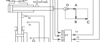
Control via analog input
The PR6000 frequency converter has two analogue inputs – AI1 and AI2. This sets it apart from other models with one analog input.
Input AI1 can be used for voltage control with an input impedance of 47 kOhm. Input AI2 has a choice, which is made by a switch: current input with an input resistance of 500 Ohms, or voltage input.
Control via digital inputs
The PR6000 converter has 8 discrete (digital) inputs: FWD (forward/stop), REW (reverse/stop) and 6 inputs DI1…DI6.
The FWD and REW inputs can operate in two- and three-wire mode, with the third wire being programmed on one of the inputs DI1…DI6. The speed control mode selection is set in parameter P077.
Digital inputs DI1...DI6 are multifunctional; they are programmed for different functions, which are launched when the corresponding input is activated.
Possible functions: multi-speed selection, acceleration/deceleration selection, forward/reverse JOG operation, stop control, frequency increase/decrease, fault alarm input, start pause, three-wire start/stop control, DC braking , error/message reset, sweep frequency operation, counter enable/reset/input. In total, you can select up to 20 different parameters, which are set in parameters P071...P076 for each input. Activation of discrete inputs occurs by short-circuiting the desired input to the COM terminal. Moreover, this can be done in different ways - via the controller output, relay contacts, sensor or manual button. The digital and analog inputs are shown below.
Serial control
When operating via the RS-485 interface, the frequency converter is controlled by a controller or a personal computer through a special RS-485/RS-232 converter adapter.
Through this interface, the converter can not only receive commands to change parameters and state, but also provide information about its current state to other devices. Also, communication with other converters can be supported via the RS-485 interface.
Next, we’ll talk about methods for operational control of inverter modes.
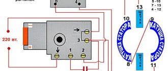
Engine start/stop
Starting and stopping the engine can be done in the following ways.
- From the control panel of the frequency converter. To do this, use the RUN, STOP/RESET buttons. If a short-term start is needed, the JOG button is used.
- By supplying a signal to the discrete inputs FWD, REW with two-wire control. For three-wire control, you need to enable one of the discrete inputs DI1...DI6 and program it accordingly. The mode is selected by parameter P077. Any of these inputs can also be used for pulse triggering (JOG command). With two-wire control, a constant signal is required at the appropriate inputs for the motor to operate. With a three-wire, a short-term signal is sufficient.
- Via a serial interface using commands from the controller. The source of the Start/Stop command in the Prostar PR6000 inverter is selected in parameter P006.
Two wire start/stop control
Three wire start/stop control
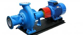
Variable Frequency Drives
Installations such as variable-frequency drives (VFDs), also called frequency converters (FCs) ). These settings allow you to change the frequency and amplitude of the three-phase voltage supplied to the electric motor, due to which a flexible change in the operating modes of the control mechanisms is achieved.
High Voltage Variable Frequency Drive
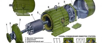
VFD design
Let's give a brief description of existing frequency converters.
Structurally, the converter consists of functionally related blocks: input transformer block (transformer cabinet); a multi-level inverter (inverter cabinet) and a control and protection system with an information input and display unit (control and protection cabinet).
The input transformer cabinet transfers energy from the three-phase power supply to a multi-winding input transformer, which distributes the reduced voltage to a multi-level inverter.
A multilevel inverter consists of unified cells - converters. The number of cells is determined by the specific design and manufacturer. Each cell is equipped with a rectifier and a DC link filter with a bridge voltage inverter using modern IGBT transistors (insulated gate bipolar transistor). The input AC current is initially rectified and then converted into alternating current with adjustable frequency and voltage using a solid-state inverter.
The resulting sources of controlled alternating voltage are connected in series into links, forming a voltage phase. The construction of a three-phase output power system for an asynchronous motor is carried out by connecting links according to the “STAR” circuit.
The protection control system is located in the control and protection cabinet and is represented by a multifunctional microprocessor unit with a power supply system from the converter's own power source, an information input/output device and primary sensors of the converter's electrical operating modes.
Frequency control
The inverter can control speed in several ways depending on the specific equipment.
- Speed control using a variable resistor installed on the keyboard (control panel) of the inverter.
- Discrete change using the Up/Down control panel keys.
- Discrete change using contacts (any two) connected to inputs DI1…DI6. When the corresponding discrete input is activated, the speed decreases or increases within specified limits with a specified step. Note. In options 2 and 3, when the power is turned on, the engine starts at the frequency set in parameter P005. During operation, the frequency can be quickly changed. If the changed frequency value needs to be remembered, parameter P155 is used.
- Speed setting using analog voltage or current signals supplied to inputs AI1, AI2. Analog signals can be combined in different ways.
- Setting in accordance with the pulse frequency at input DI6.
- Via RS-485 interface from the controller. The frequency control channel is selected using parameter P004. The upper and lower operating frequencies are set in parameters P009 and P010. The speed of the engine in pulse (jog) mode JOG is set by parameter P052.
According to the latest statistics, approximately 70% of all electricity generated in the world is consumed by electric drives. And every year this percentage is growing.
With a correctly selected method of controlling an electric motor, it is possible to obtain maximum efficiency, maximum torque on the shaft of the electric machine, and at the same time the overall performance of the mechanism will increase. Efficiently operating electric motors consume a minimum of electricity and provide maximum efficiency.
For electric motors powered by an inverter, the efficiency will largely depend on the chosen method of controlling the electrical machine. Only by understanding the merits of each method can engineers and drive system designers get the maximum performance from each control method.
For asynchronous electric motors connected to a frequency converter, the following main control methods exist:
1. Scalar
· Scalar U/f control;
· Scalar U/f control with encoder;
2. Vector
· Open-loop vector control;
· Closed loop vector control;
All four methods use PWM pulse width modulation, which changes the width of a fixed signal by varying the width of the pulses to create an analog signal.
SCALAR REGULATION
U/f control method
The scalar method of controlling an AC induction motor is to maintain a constant voltage/frequency (U/f) ratio throughout the entire operating speed range, while only controlling the magnitude and frequency of the supply voltage.
The U/f ratio is calculated based on the nominal values (voltage and frequency) of the controlled AC motor. By maintaining a constant value of the U/f ratio, we can maintain a relatively constant magnetic flux in the motor gap. If the U/f ratio increases then the motor becomes overexcited and vice versa if the ratio decreases the motor is in an unexcited state.
Dependence of motor supply frequency on time with scalar control
Changing the motor supply voltage with scalar control
At low speeds it is necessary to compensate for the voltage drop across the stator resistance, so the U/f ratio at low speeds is set higher than the nominal value. The scalar control method is most widely used to control asynchronous electric motors. It is often used in simple electric drive systems due to its simplicity and the minimum number of parameters required for operation. This control method does not require the mandatory installation of an encoder and mandatory settings for a variable-frequency electric drive. This leads to lower costs for auxiliary equipment (sensors, feedback wires, relays, etc.). U/f control is quite often used in high-frequency equipment, for example, it is often used in CNC machines to drive spindle rotation.
U/f is the only way to regulate the speed of an asynchronous electric motor, which allows the control of several electric drives from one frequency converter. Accordingly, all machines start and stop simultaneously and operate at the same frequency.
But this control method has several limitations. For example, when using the U/f control method without an encoder, there is absolutely no certainty that the shaft of an asynchronous machine rotates. In addition, the starting torque of an electric machine at a frequency of 3 Hz is limited to 150%. Yes, the limited torque is more than enough to accommodate most existing equipment. For example, almost all fans and pumps use the U/f control method.
This method is relatively simple due to its looser specification. Speed regulation is typically in the range of 2% - 3% of the maximum output frequency. The speed response is calculated for frequencies above 3 Hz. The response speed of the frequency converter is determined by the speed of its response to changes in the reference frequency. The higher the response speed, the faster the electric drive will respond to changes in the speed setting.
The speed control range when using the U/f method is 1:40. By multiplying this ratio by the maximum operating frequency of the electric drive, we obtain the value of the minimum frequency at which the electric machine can operate. For example, if the maximum frequency value is 60 Hz and the range is 1:40, then the minimum frequency value will be 1.5 Hz.
The U/f pattern determines the relationship between frequency and voltage during operation of a variable frequency drive. According to it, the rotation speed setting curve (motor frequency) will determine, in addition to the frequency value, also the voltage value supplied to the terminals of the electric machine.
Operators and technicians can select the desired U/f control pattern with one parameter in a modern frequency converter. Pre-installed templates are already optimized for specific applications. There are also opportunities to create your own templates that will be optimized for a specific variable frequency drive or electric motor system.
Devices such as fans or pumps have a load torque that depends on their rotation speed. The variable torque (picture above) of the U/f pattern prevents control errors and improves efficiency. This control model reduces magnetizing currents at low frequencies by reducing the voltage on the electrical machine.
Constant torque mechanisms such as conveyors, extruders and other equipment use a constant torque control method. With constant load, full magnetizing current is required at all speeds. Accordingly, the characteristic has a straight slope throughout the entire speed range.
f control method with encoder
With the scalar control method, the speed of an induction motor is controlled by setting the stator voltage and frequency, so that the magnetic field in the gap is maintained at the desired value. To maintain a constant magnetic field in the gap, the U/f ratio must be constant at different speeds.
As the speed increases, the stator supply voltage must also increase proportionally. However, the synchronous frequency of an induction motor is not equal to the shaft speed, and the slip of an asynchronous motor depends on the load. Thus, a scalar open-loop control system cannot accurately control speed when a load is present. To solve this problem, speed feedback, and therefore slip compensation, can be added to the system.
Thus, if it is necessary to increase the accuracy of rotation speed control, an encoder is added to the control system. The introduction of speed feedback using an encoder allows you to increase the control accuracy to 0.03%. The output voltage will still be determined by the specified U/f pattern.
This control method is not widely used, since the advantages it provides compared to standard U/f functions are minimal. Starting torque, response speed and speed control range are all identical to standard U/f. In addition, when operating frequencies increase, problems with the operation of the encoder may arise, since it has a limited number of revolutions.
When to use scalar control
Scalar control of AC motors is a good alternative for applications where there is no variable load and high dynamic loads (fans, pumps). Scalar control does not require a rotor position sensor to operate, and the rotor speed can be estimated from the frequency of the supply voltage. When scalar control is used, a high-performance digital signal processor is not required as is the case with vector control.
Disadvantages of Scalar Control
With scalar motor control, the stator currents are not directly controlled.
And the process of scalar regulation of a synchronous motor with permanent magnets can easily become uncontrollable (leave the synchronous state), especially when the load torque exceeds the value of the limiting torque of the electric drive. The scalar method is not suitable for controlling a synchronous motor at low speeds with high dynamic loads.
scalar control method is relatively simple to implement, but has several significant disadvantages:
· firstly, if a speed sensor is not installed, it is impossible to control the rotation speed of the shaft of an asynchronous motor, since it depends on the load (the presence of a speed sensor solves this problem), and in the case of a synchronous motor, when the load changes, you can completely lose control;
Secondly, you cannot control the moment. Of course, this problem can be solved using a torque sensor, but the cost of installing it is very high, and will most likely be higher than the electric drive itself. In this case, torque control will be very inertial;
· it is also impossible to control torque and speed at the same time.
Scalar control is sufficient for most tasks in which an electric drive is used with an engine speed control range of up to 1:10.
When maximum speed is required, the ability to regulate over a wide range of speeds and the ability to control the torque of the electric motor, vector control is used.
VECTOR CONTROL
Vector control is a method of controlling brushless AC motors, which allows you to independently and practically inertia-free control the rotation speed and torque on the motor shaft.
The main idea of vector control is to control not only the magnitude and frequency of the supply voltage, but also the phase. In other words, the magnitude and angle of the space vector are controlled. Vector control has higher performance compared to scalar control. Vector control eliminates almost all the disadvantages of scalar control.
Open-loop vector control
Open-loop vector control (VC) is used for broader and more dynamic speed control of an electrical machine. When starting from a frequency converter, electric motors can develop a starting torque of 200% of the rated torque at a frequency of only 0.3 Hz. This significantly expands the list of mechanisms where an asynchronous electric drive with vector control can be used. This method also allows you to control the machine's torque in all four quadrants.
The torque is limited by the motor. This is necessary to prevent damage to equipment, machinery or products. The torque value is divided into four different quadrants, depending on the direction of rotation of the electric machine (forward or reverse) and depending on whether the electric motor implements regenerative braking mode. Limits can be set for each quadrant individually, or the user can set the overall torque in the frequency converter.
The motor mode of an asynchronous machine will be provided that the magnetic field of the rotor lags behind the magnetic field of the stator. If the rotor magnetic field begins to outstrip the stator magnetic field, then the machine will enter regenerative braking mode with energy release; in other words, the asynchronous motor will switch to generator mode.
For example, a bottle capping machine may use torque limiting in quadrant 1 (forward direction with positive torque) to prevent overtightening of a bottle cap. The mechanism moves forward and uses the positive torque to tighten the bottle cap. But a device such as an elevator with a counterweight heavier than the empty car will use quadrant 2 (reverse rotation and positive torque). If the cabin rises to the top floor, then the torque will be opposite to the speed. This is necessary to limit the lifting speed and prevent the counterweight from free falling, since it is heavier than the cabin.
Current feedback in these frequency converters allows you to set limits on the torque and current of the electric motor, since as the current increases, the torque also increases. The output voltage of the inverter may increase if the mechanism requires more torque, or decrease if its maximum permissible value is reached. This makes the vector control principle of an asynchronous machine more flexible and dynamic compared to the U/F principle.
Also, frequency converters with vector control and open loop have a faster speed response of 10 Hz, which makes it possible to use it in mechanisms with shock loads. For example, in rock crushers, the load is constantly changing and depends on the volume and dimensions of the rock being processed.
Unlike the U/F control pattern, vector control uses a vector algorithm to determine the maximum effective operating voltage of the electric motor.
Vector control of the VU solves this problem due to the presence of feedback on the motor current. As a rule, current feedback is generated by the internal current transformers of the frequency converter itself. Using the obtained current value, the frequency converter calculates the torque and flux of the electrical machine. The basic motor current vector is mathematically split into a magnetizing current and torque vector.
Using the data and parameters of the electrical machine, the inverter calculates the magnetizing current and torque vectors. To achieve maximum performance, the frequency converter must keep the vector data separated by an angle of 900. This is significant since sin 900 = 1, and a value of 1 represents the maximum torque value.
In general, vector control of an induction motor provides tighter control. The speed regulation is approximately ±0.2% of the maximum frequency, and the regulation range reaches 1:200, which can maintain torque when running at low speeds.
Vector feedback control
Feedback vector control uses the same control algorithm as open-loop VAC. The main difference is the presence of an encoder, which allows the variable frequency drive to develop 200% starting torque at 0 rpm. This point is simply necessary to create an initial moment when moving off elevators, cranes and other lifting machines, in order to prevent subsidence of the load.
The presence of a speed feedback sensor allows you to increase the system response time to more than 50 Hz, as well as expand the speed control range to 1:1500. Also, the presence of feedback allows you to control not the speed of the electric machine, but the torque. In some mechanisms, it is the torque value that is of great importance. For example, winding machine, clogging mechanisms and others. In such devices it is necessary to regulate the torque of the machine.
Advantages of vector control:
· high accuracy of speed control;
· smooth start and smooth rotation of the engine over the entire frequency range;
· quick response to load changes: when the load changes, there is practically no change in speed;
· increased control range and control accuracy;
· losses due to heating and magnetization are reduced, and the efficiency of the electric motor is increased.
The disadvantages of vector control include:
· the need to set the parameters of the electric motor;
· large speed fluctuations at constant load;
· high computational complexity.
Comparison table of frequency converter control methods.
| Control method | Speed control range | Speed error3,% | Torque rise time, ms | Starting torque | Price | Description | ||
| Scalar | 1:101 | 5-10 | Not available | Short | Very low | It has a slow response to load changes and a small speed control range, but is easy to implement. | ||
| Vector | Linear | Field-oriented control | >1:2002 | 0 | <1-2 | High | High | Allows you to smoothly and quickly control the main engine parameters - torque and speed. For this method to work, information about the rotor position is required. |
| Direct torque control with FDA | >1:2002 | 0 | <1-2 | High | High | A hybrid method developed to combine the advantages of https://engineering-solutions.ru/motorcontrol/vector/#foc and https://engineering-solutions.ru/motorcontrol/vector/#dtc. | ||
| Nonlinear | Direct torque control with switching table | >1:2002 | 0 | <1 | High | High | It has high dynamics and a simple circuit, but a characteristic feature of its operation is high current and torque ripples. | |
| Direct self-government | >1:2002 | 0 | <1-2 | High | High | It has an inverter switching frequency lower than other methods and is designed to reduce losses when controlling high-power electric motors. | ||
Bibliography:
1. Botan Electric. “How to choose the right frequency converter control method? https://elenergi.ru, 2016
2. Cristian Busca. "Open loop low speed control for PMSM in high dynamic application. - Aalborg, Denmark.": Aalborg universitet, 2010
3. Bial Akin, “Nishant Garg. Scalar (V/f) control of 3-phase induction motors. Application report. SPRABQ8.- Dallas, USA.": Texas Instruments
4. Articles https://engineering-solutions.ru
Emergency stop of the inverter
In addition to a regular stop, the Stop function with a specified deceleration uses two methods of emergency stopping the engine and turning off the inverter.
- Emergency stop by power interruption. To do this, manufacturers recommend installing a three-phase linear contactor before powering the inverter, the power supply of the coil depends on the state of the emergency circuit of all equipment. When you press the “Emergency Stop” button or in another emergency, the power to the contactor is turned off and the voltage from the inverter is removed. This will ensure that the engine stops.
- The function of discrete input DI1…DI6 “External device fault alarm” is used. If you program the desired input for this function, the inverter will stop if an alarm occurs.
Other useful materials:
Subtleties of setting up a frequency converter FAQ on electric motors Setting up a frequency converter to operate on multiple motors Purpose and types of encoders
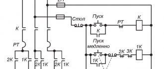
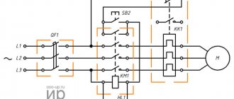
Frequency converter connection diagram
After the modification, the entire circuit of the machine, containing two drives, looks like this:
Frequency converter connection diagram
First of all, I will say that if you do everything wisely, then you need to provide protection at the input - install high-speed fuses or, at worst, circuit breakers with characteristic “B”. But what is, that is - the only defense is the Soviet 3p S6.
The extraction and polishing drives have two common parts - power and the “Stop” button. The “Stop” button (SB3) has two electrically independent contacts that stop both drives at once.
Particularly picky readers will definitely reproach me for my words that “zero is not used in the machine’s power supply.” But I have a ready answer)))
The hood drive is connected according to the classic self-retaining scheme, which I have written about more than once. Links are at the beginning of the article.
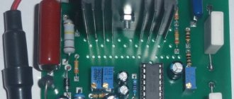
Let's take a closer look at what interests us - the inverter connection diagram:
Working diagram of Delta inverter connection
As for the power part, I already said, everything is simple there.
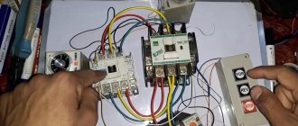
In terms of management. The names of the terminals are indicated on the diagram; they can also be seen in the installation photo. In order for the whole circuit to work correctly, all these terminals need to be programmed correctly, without this there is nowhere to connect the inverter. Therefore, setting up the inverter and connecting it are two inextricably linked concepts.
On setting up and connecting the inverter