Connecting a three-phase motor
This means an asynchronous electric motor, winding connection - star or triangle, connection to a 380V network.
For the engine to operate, the working neutral conductor N (Neutral) is not needed, but the protective conductor (PE, Protect Earth) must be connected for safety reasons.
I have already written in detail about the principles of constructing 380V networks in articles about a three-phase meter and voltage relay.
Other related articles – Difference between three-phase and single-phase voltage, Grounding systems.
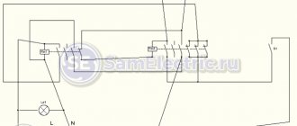
In the most general case, the diagram will look like this, as shown at the beginning of the article. Indeed, why not turn on the engine like a regular light bulb, only the switch will be a “three-key”?
2. Connecting the engine through a switch or circuit breaker
But no one even turns on a light bulb just like that; the lighting network and, in general, any load is always turned on only through circuit breakers.
Read more about replacing and installing circuit breakers here. And about their parameters and choice – here.
Asynchronous motor control
Direct connection to mains power
The use of magnetic starters allows you to control asynchronous electric motors by directly connecting the motor to an alternating current network.
Using magnetic starters you can implement the following circuit:
- non-reversible start: start and stop;
- reverse start: start, stop and reverse.
The use of a thermal relay makes it possible to protect the electric motor from current values much higher than the rated value.
Non-reversible circuit
Irreversible diagram for connecting a three-phase asynchronous electric motor to a three-phase alternating current network through a magnetic starter L1, L2, L3
- contacts for connecting to a three-phase alternating current network,
QF1
- circuit breaker,
SB1
- stop button,
SB2
- start button,
KM1
- magnetic starter,
KK1
- thermal relay,
HL1
- signal lamp,
M
- three-phase asynchronous motor
Reversible circuit
Reversible diagram for connecting a three-phase asynchronous electric motor to a three-phase alternating current network through magnetic starters L1, L2, L3
- contacts for connecting to a three-phase alternating current network,
QF1
- circuit breaker,
KM1, KM2
- magnetic starters,
KK1
- thermal relay, Mmm - three-phase asynchronous motor,
SB1
- stop button,
SB2
- forward start button,
SB3
- start button “back” (reverse),
HL1, HL2
- signal lamps
Frequency control of an asynchronous electric motor
To regulate the rotation speed and torque of an asynchronous motor, a frequency converter is used. The operating principle of a frequency converter is based on changing the frequency and voltage of alternating current.
Functional diagram of variable frequency drive
- Depending on the functionality, frequency converters implement the following control methods with an asynchronous electric motor:
- scalar control
; - vector control
.
Scalar control
is simple and cheap to implement, but has the following disadvantages - slow response to load changes and a small control range. Therefore, scalar control is usually used in tasks where the load is either constant or varies according to a known law (for example, fan control).
Scalar control of an asynchronous motor with a speed sensor
Vector control
used in tasks where it is necessary to independently control the speed and torque of an electric motor (for example, an elevator), which, in particular, makes it possible to maintain a constant rotation speed with a changing load torque. At the same time, vector control is the most effective control in terms of efficiency and increasing the operating time of the electric motor.
Among the vector control methods for asynchronous electric motors, the most widely used are field-oriented control and direct torque control.
Field-oriented control of an asynchronous electric motor using a rotor position sensor
Field-oriented control
allows you to smoothly and accurately control the movement parameters (speed and torque), but its implementation requires information about the direction and vector of the engine rotor flux linkage.
- According to the method of obtaining information about the position of the flux linkage of the electric motor rotor, the following are distinguished:
- field-oriented sensor control;
- field-oriented control without a sensor: the position of the rotor flux linkage is calculated mathematically based on the information available in the frequency converter (supply voltage, stator voltages and currents, resistance and inductance of the stator and rotor windings, number of motor pole pairs).
Field-oriented control of an asynchronous electric motor without a rotor position sensor
Direct torque control
It has a simple circuit and high operating dynamics, but at the same time high torque and current ripples.
Diagram of connecting a three-phase motor to the network via a circuit breaker
Therefore, in more detail, the general case will look like this:
3. Connecting the motor via a circuit breaker. PRACTICAL SCHEME
Diagram 3 shows a circuit breaker that protects the motor from overcurrent (“rectangular” bends in the supply lines) and from short circuits (“round” bends). By circuit breaker I mean a regular three-pole circuit breaker with a load thermal characteristic of C or D.
Let me remind you that in order to approximately select (estimate) the required thermal current of the thermal protection setting, you need to multiply the rated power of the three-phase motor (indicated on the nameplate) by 2.
Circuit breaker for turning on the electric motor. The current is 10A, through which you can turn on a 4 kW motor. No more and no less.
Scheme 3 has the right to life (due to poverty or ignorance of local electricians).
It works great, just as twisting copper and aluminum can work for many years. And one “fine” day the twist will burn out. Or the engine will burn out.
If you use such a circuit, you need to carefully select the current of the machine so that it is 10-20% greater than the operating current of the motor. And select the characteristic of the thermal release D, so that during a difficult start the machine does not trip.
For example, a 1.5 kW engine. We estimate the maximum operating current - 3A (real operating current may be less, we need to measure it). This means that the three-pole circuit breaker must be set to 3 or 4A, depending on the starting current.
The advantage of this motor connection diagram is the price and ease of execution and maintenance. For example, where there is one engine, and it is turned on manually for the entire shift. The disadvantages of such a scheme with switching on via an automatic machine are:
- Inability to regulate the thermal current of the machine. In order to reliably protect the engine, the shutdown current of the circuit breaker must be 10-20% greater than the rated operating current of the engine. The motor current must be periodically measured with clamps and, if necessary, the thermal protection current must be adjusted. But a regular machine does not have the ability to adjust (.
- Inability to remotely and automatically turn on/off the engine.
These shortcomings can be eliminated; the diagrams below will show how.
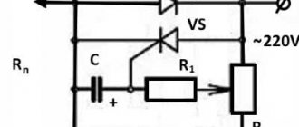
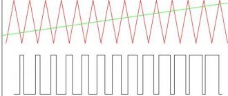
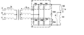
Electric drive control module based on PIC16C62 microcontroller and IR2131 driver
For some relatively simple electric drive control tasks, you can use non-specialized microcontrollers that the developer is used to and that are freely sold on our market. In [1], the basic requirements for microcontrollers were shown and a range of modern tasks were described, where the use of specialized microcircuits is the most reasonable solution. In this article we show the possibility of using the PIC16C62 microcontroller from Microchip to solve simple drive control problems that are often encountered in everyday life. Basically, the proposed circuit is designed to control three-phase asynchronous motors when a single-phase 220 V network is available. The circuit shown in Fig. 1, consists of a three-phase power inverter, a control signal generator and a mating element - a driver for the inverter switches. Let's look at these elements and describe some algorithms that can be implemented on them.
Rice. 1. Asynchronous motor control circuit
The IR2131 (or IR2130) microcircuit from INTERNATIONAL RECTIFIER, attractive in all respects, is no longer news, but is rarely found in domestic developments. One of the reasons for this is its relatively high cost, but if we take into account that the price of such products in our market strongly depends on demand, then with a certain risk we can recommend it to the developer for use in products where price is the determining factor. The IR2131 chip is a 6-switch driver (IGBT or MOSFET), which has three outputs for controlling the lower bridge switches and three outputs for switches with a floating control potential. It provides current protection, which turns off all switches and generates a FAULT error signal when the signal at the ITRIP pin exceeds 0.5 V. This is convenient for the developer, since organizing such protection only requires him to correctly determine the value of the sensor resistor. The driver inputs are consistent with TTL logic, which allows it to be controlled using microcontrollers with 5-V power supply without additional level converters. In addition, the IR2131 has a separate input for turning off all keys and an error signal reset input, while the IR2130 instead has a built-in load current amplifier, and the error trigger is reset when an inactive level is applied to all control inputs. The permissible voltage on the inverter with which the microcircuit operates is 600 V. Currently, INTERNATIONAL RECTIFIER produces similar drivers with an operating voltage of 1200 V. In Fig. Figure 1 shows the simplest circuit of a three-phase bridge using IRF740 transistors, which are controlled from IR2131. To generate bridge control signals, you can use an inexpensive Microchip PIC16C62 microcontroller (if you need to additionally process the analog signal, the PIC16C73 is recommended). With a low rated power, the electric drive is powered from a 220 V AC mains through connector X1, and it is recommended to use IRF740 transistors (VT2–VT7) in a three-phase bridge. Power up to 5 kW can be passed through them. At high powers, it is necessary to switch to power from a three-phase 380 V network and use IGBT transistors. Our work experience has shown the advisability of shunting gate resistors R13–R18 with reverse diodes VD7–VD12. This allows you to significantly reduce dynamic losses when switching off. The generated voltage is supplied to the engine through connector X2. If the capacity of the C12 filter is large and there is no element limiting the charge current of this capacity, then the bridge diodes will gradually be destroyed each time it is turned on. To prevent current surge through the rectifier, thermistor R19 must be turned on. When operating from a single-phase 220 V network, it may be necessary to introduce a current consumption correction module (this is especially true for high drive powers). For some designs, where 100-Hz torque ripple on the motor shaft does not lead to undesirable consequences, you can completely abandon the use of capacitor C12. Capacitor C11 (ceramic or polypropylene) must be located as close as possible to the bridge transistors, since field-effect and IGBT transistors “do not like” overvoltages that will occur during switching on parasitic inductances of the circuit. Power is supplied to driver DD2 from zener diode VD2 through quenching resistor R12. At low inverter frequencies (up to 3 kHz), 40 kOhm is sufficient for normal power supply of the control system. To increase the efficiency of the system, you can use a standard switching step-down regulator using PIC16C73 resources as a PWM controller. Bootstrap capacitors C7–C9 are charged through diodes VD4–VD6 when the corresponding lower switch is turned on. The supply voltage of the IR2131 is selected depending on the desired degree of saturation of the power transistor. The recommended value is 15–20 V. Reducing the supply voltage of any of the channels below 8 V causes the key to immediately lock. The value of the resistive current sensor R10 is selected depending on the rated power of the electric drive and the permissible overcurrent (R10 = 0.5 V / Iperm). The integrating link R11-C10 prevents false operation of the current protection at switching moments; a sufficient time constant is 0.5 μs. If the signal at the ITRIP input exceeds the level of 0.5 V, all keys are locked and a FAULT error signal is issued (open collector output).
Connecting a three-phase motor via a manual starter
A manual starter or automatic motor is a more advanced device. It has “Start” and “Stop” buttons, or an “On-Off” knob. Its advantage is that it is specially designed for starting and protecting the engine. The start is still manual, but the operating current can be adjusted within certain limits.
4. Connecting the motor via a manual starter. PRACTICAL SCHEME
Since motors usually have a high starting current, motor circuit breakers (automatic motors) usually have a thermal protection characteristic of type D. That is it can withstand short-term (starting) overloads of approximately 10 times the nominal value.
Manual motor starter with additional control contact.
Here's what's on the side:
Motor circuit breaker - characteristics on the side wall
Setting current (thermal) – from 17 to 23 A, set manually. Cut-off current (trigger during short circuit) – 297 A.
In principle, a manual starter and an automatic motor are the same device. But the starter shown in the photo can switch the power supply to the engine. And the automatic motor constantly supplies power (three phases) to the contactor, which, in turn, switches the power to the motor. In short, the difference is in the connection diagram.
The advantage of the scheme is that you can adjust the thermal current setting. The disadvantage is the same as in the previous scheme - there is no remote activation.
Motor connection diagram via magnetic starter
This wiring diagram for a three-phase motor should be given the closest attention. It is most common in all industrial equipment produced until about the 2000s. And in new Chinese simple machines it is still used to this day.
An electrician who does not know it is like a surgeon who cannot distinguish an artery from a vein; as a lawyer who does not know Article 1 of the Constitution of the Russian Federation; like a dancer who does not distinguish a waltz from a tectonic.
In this circuit, three phases go to the motor not through the machine, but through the starter. And the starter is turned on/off using the “ Start ” and “ Stop ” buttons, which can be placed on the control panel through 3 wires of any length.
An example of such a circuit is in the article about restoring the circuit of a hydraulic press, see the last circuit in the article, KM0 starter. Read about the selection, design and characteristics of electromagnetic starters (contactors) here.
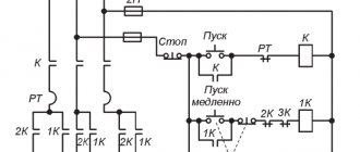
5. Diagram of connecting the motor through a starter with start-stop buttons
Here, power to the control circuit comes from phase L1 (wire 1 ) through a normally closed (NC) “Stop” button (wire 2 ).
If you now press the “Start” button, the power circuit of the coil of the KM electromagnetic starter will close (wire 3
), its contacts will close, and three phases will go to the motor. But in such schemes, in addition to three “power” contacts, the starter has one more additional contact. It is called a “locking” or “self-latching contact”.
When the electromagnetic starter is turned on by pressing the SB1 “Start” button, the self-retaining contact also closes. And if it is closed, then even if the “Start” button is pressed, the power circuit of the starter coil will still remain closed. And the engine will continue to run until the “Stop” button is pressed.
Since the topic of magnetic starters is very extensive, it is included in a separate article: Connection diagrams for a magnetic starter. The article has been significantly expanded and supplemented. Everything is covered there - connecting various loads, protection (thermal and short-circuit), reversing circuits, control from different points, etc. The numbering of the schemes has been preserved. I recommend.
Connecting a 380 V electric motor
June 23, 2014
Three-phase electric motors are more efficient than 220-volt single-phase motors. If you have a 380 Volt input in your house or garage, then be sure to buy a compressor or machine with a three-phase electric motor. This will ensure more stable and economical operation of the devices. To start the motor, you will not need various starting devices and windings, because a rotating magnetic field appears in the stator immediately after connecting to a 380-volt power supply.
Selecting a motor switching circuit
the connection diagrams for 3-phase motors using magnetic starters in previous articles: “Connection diagram for electric motors with a thermal relay” and “Reverse starting diagram”.
It is also possible to connect a three-phase motor to a 220 Volt network using capacitors according to this scheme. But there will be a significant drop in the power and efficiency of its operation.
of a 380 V asynchronous motor
You must take into account that when connected with a star, the start will be smooth, but in order to achieve full power, you need to connect the motor with a triangle. In this case, the power will increase by 1.5 times, but the current when starting powerful or medium-sized motors will be very high, and can even damage the insulation of the windings.
Before connecting the electric motor, read its characteristics in the passport and on the nameplate. This is especially important when connecting 3-phase electric motors made in Western Europe, which are designed to operate from a mains voltage of 400/690. An example of such a nameplate is in the picture below. Such motors are connected only in a “delta” configuration to our electrical network. But many installers connect them in the same way as domestic ones in a “star” and the electric motors burn out, especially quickly under load.
In practice, all domestically produced 380 Volt electric motors are connected by a star. Example in the picture. In very rare cases, in production, in order to squeeze out all the power, a combined star-delta connection circuit is used. You will learn about this in detail at the very end of the article.
Star-delta motor connection diagram
In some of our electric motors, only 3 ends come out of the stator with windings - this means that a star is already assembled inside the motor. All you have to do is connect 3 phases to them. And in order to assemble a star, both ends of each winding or 6 terminals are needed.
The ends of the windings in the diagrams are numbered from left to right. Numbers 4, 5 and 6 are connected to 3 phases A-B-C from the mains.
When a three-phase electric motor is connected by a star, the beginnings of its stator windings are connected together at one point, and 3 phases of 380 Volt power supply are connected to the ends of the windings.
When connected in a triangle, the stator windings are connected to each other in series. In practice, it is necessary to connect the end of one winding to the beginning of the next. 3 power phases are connected to the three points connecting them to each other.
Star-delta connection
To connect the motor according to a rather rare star circuit at startup, with subsequent transfer to a delta circuit for operation in operating mode. This way we can squeeze out maximum power, but it turns out to be a rather complex circuit without the possibility of reversing or changing the direction of rotation.
For the circuit to operate, 3 starters are required. The first K1 is connected to the power supply on one side, and on the other - the ends of the stator windings. Their origins are connected to K2 and K3. From starter K2, the beginning of the windings are connected respectively to other phases according to a triangle diagram. When K3 is turned on, all 3 phases are short-circuited with each other and a star operating circuit is obtained.
Connecting a three-phase motor via electronic devices
All methods of starting the engine described above are called Starting by direct voltage supply. Often, in powerful drives, such a start-up is a difficult test for the equipment - belts burn, bearings and fasteners break, etc.
Therefore, the article would be incomplete if I did not mention current trends. Nowadays, electronic power devices are increasingly used to connect a three-phase motor instead of electromagnetic starters. By this I mean:
- Solid state relays - their power elements are thyristors (triacs), which are controlled by an input signal from a button or from a controller. There are both single-phase and three-phase. Here is my article.
- Soft (soft) starters (soft starters, soft starters) are advanced solid state machines. You can set the protection current, acceleration/deceleration time, turn on reverse, etc. And there is an article on this topic. Practical application of soft starters is here.
- Frequency converters are the most advanced device that humanity has come up with for connecting an electric motor. Describing frequency generators is not the job of one article.
And if you are at all interested in what I write about, subscribe to receive new articles and join the group on VK!
The advantages of such devices are obvious (first of all, the absence of contacts as such), but there is only one drawback - the price. And here’s what their connection diagram might look like:
10. Connecting a three-phase motor - general circuit with electronic power
Download
If the topic interests you more deeply, I recommend that you read the literature listed on the page.
Here is one of the books listed there: • Lomonosov, V.Yu.; Polivanov, K.M.; Mikhailov, O.P. Electrical engineering. / Lomonosov, V.Yu.; Polivanov, K.M.; Mikhailov, O.P. Electrical engineering. One of the best books on the basics of electrical engineering. The presentation begins with the very basics: it explains what voltage, current and resistance are, provides instructions for calculating the simplest electrical circuits, and talks about the relationship and interdependence of electrical and magnetic phenomena. Explains what alternating current is and how an alternating current generator works. It describes what a capacitor is and what an inductor is, what their role is in alternating current circuits. It is explained what three-phase current is, how three-phase current generators are designed and how its transmission is organized. A separate chapter is devoted to semiconductor devices: it talks about semiconductor diodes, transistors and thyristors; on the use of semiconductor devices for rectifying alternating current and as semiconductor switches. The achievements of microelectronics are briefly described. The last third of the book is entirely devoted to electrical machines, units and equipment: chapter 10 deals with direct current machines (generators and motors); Chapter 11 is devoted to transformers; AC machines (single-phase and three-phase, synchronous and asynchronous) are described in detail in Chapter 12; switches, electromagnets and relays are described in Chapter 13; Chapter 14 deals with electrical diagramming. The last, chapter 15, is devoted to measurements in electrical engineering. This book is an excellent way to learn the basics of electrical engineering, to understand the fundamental principles of the operation of electrical machines and units., zip, 13.87 MB, downloaded: 2730 times./
• Starting and protection of AC motors / Starting and protection of AC motors. Starting and braking systems for AC motors. Protection devices and fault analysis of AC motors. Guide to selecting protection devices. Manual from Schneider Electric, pdf, 1.17 MB, downloaded: 2108 times./