Addressable LED strip is a decoration for any Arduino project. With its help, you can create light music, smart lighting for a TV, creeping lines and other projects that require displaying information on a wide screen. Thanks to the built-in controllers, you can control each of the LED strips individually, controlling them like pixels on the screen. In this article we will figure out how an addressable LED strip works, how to connect it to Arduino, and which libraries are best to use for control.
Addressable LED strips
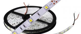
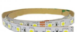
An LED strip is a set of connected LEDs that can be simultaneously supplied with power. Ordinary tapes are familiar to everyone; they are used everywhere today. Addressable LED strip also uses LEDs, but the light-emitting diode can be controlled separately and independently of the others. Thus, addressable strips can be used to more intelligently control the light output on individual sections of the strip, turning the backlight on or off at the right time and in the right place.
Addressable LED strip WS2811
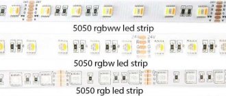
Today, the most popular are multi-colored RGB LED strips, which allow you to obtain a variety of colors. Thanks to the design, it is possible to control the color of each LED, which allows you to create original lighting effects. The main difference between an addressable LED strip and a regular RGB strip is the presence of special controllers (designed in the form of microcircuits) near each LED, which makes it possible to individually address and regulate each shade.
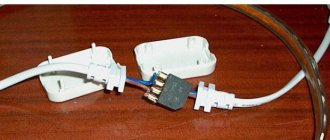
As a rule, the tape contains 3-4 contacts for connection. Two pins are used for power - 5 Volts and ground, the remaining one or two are logical, to control the glow.
The smart tape is controlled using a digital protocol. This means that the device cannot be controlled without a control controller. By the way, when you touch a digital input, several diodes may light up - this is due to the fact that interference appears, which the controller takes for commands.
The most popular addressable LED strips are devices based on WS2812b and WS2811 chips. In the first case, the chip is located directly inside the LED, that is, one device controls the glow of one emitting diode. The tape's power supply is 5 volts. In the second case, the chip is placed separately, and 3 diodes are connected to it. Power – 12 volts.
FAQ
Main questions
Q: How to download from this fucking site? A: On the main page of the project (where you read this text) at the top right there is a green Clone or download button, click it, there will be a Download ZIP
Q: I downloaded some kind of .zip file, where does it go now? A: This is an archive. You can open it using standard Windows tools, but I think everyone has WinRAR installed on their computer, the archive needs to be right-clicked and extracted.
Q: The computer does not react in any way to connecting the Arduino! A: Perhaps you have a USB charging cable, but you just need a data cable through which you can transfer data
Q: Error! The sketch doesn't compile! A: The path to the sketch should not contain Cyrillic. Put it in the root of the disk.
Q: How much does it cost? A: I don't sell anything.
Buy addressable LED strip
ws2812 tapes are quite common on the Russian market; they can be easily found in numerous specialized stores. We can recommend the online store Giant4.Ru with a fairly wide range of different LED strips and quite low prices comparable to Ali. If you have the opportunity and desire to wait for goods from Aliexpress, then below we have put together some popular options from reliable suppliers:
| Addressable LED strip 1m/4m/5m WS2812B 30/60/144 pixels,IP30/IP65/IP67 DC5V | LED strip DC5V WS2812B 1m/4m/5m 30/60/74/96/144 pixels/leds/m from a reliable supplier | Addressable LED strip DC5V 1m/4m/5m WS2812B |
How addressable LED strip works
The principle of operation of the tape is as follows. It is divided into segments, each of which contains an LED and a capacitor. They are all connected in parallel, and data is transferred sequentially from one segment to another. Management is carried out by a controller in which the operating program is prescribed. You can control the tape through the Arduino platform.
Address tape marking:
- Black PCB / White PCB – substrate colors;
- 1m/5m – length of address tape;
- 30/60/74, etc. – how many LEDs are there per 1 meter of strip;
- IP30, IP65, IP67 – degree of moisture and dust resistance of the tape =.
Addressable LED strips are used to assemble full-fledged modules, in the construction of lamps with soft lights control, for decorative lighting, and in the construction of diode screens for street advertising.
Video instructions and videos
Training video on the HomeMade channel:
Video on creating a ticker based on the ws2112 tape
SOME INFO
- Color is encoded in 3 bytes, that is, its depth is 24 bits. We have three colors, each coded with a number from 0 to 255, in total we have 256*256*256 = 16,777,216 colors, 16.8 million shades can be received by EVERY LED in the strip. When programming, colors are specified in hexadecimal encoding of the form 0xFFFFFF. The color itself is specified here in three bytes: red green blue, red will be FF0000, blue 0000FF, green 00FF00, that is, each color has a brightness, which is specified by a hexadecimal number from 00 to FF. For example, pale yellow will be 555500 like this. When using the library FastLED You have access to a bunch of pre-configured colors; their names and codes can be found here.
You can find color codes here https://getcolor.ru/
Addressable LED strip is a decoration for any Arduino project. With its help, you can create light music, smart lighting for a TV, creeping lines and other projects that require displaying information on a wide screen. Thanks to the built-in controllers, you can control each of the LED strips individually, controlling them like pixels on the screen. In this article we will figure out how an addressable LED strip works, how to connect it to Arduino, and which libraries are best to use for control.
WS2812b based tape
ws2812b-based tape
The ws2812b-based tape is more advanced than its predecessor. The PWM driver in the address strip is compact and is placed directly in the light-emitting diode housing.
The main advantages of ws2812b-based tape:
- compact dimensions;
- ease of control;
- control is carried out via just one line + power wires;
- the number of LEDs connected in series is not limited;
- low cost - buying three LEDs and a driver for them separately will cost much more.
The tape is equipped with four outputs:
- nutrition;
- data output;
- general contact;
- data input.
The maximum current of one addressable LED is 60 milliamps. Operating temperatures range from -25 to +80 degrees. The supply voltage is 5 V +-0.5.
PWM tape drivers are 8-bit - 256 gradations of brightness are possible for each color. To set the brightness, 3 bytes of information are needed - 8 bits from each LED. Information is transmitted via a single-line protocol at a fixed speed. Zeros and ones are encoded by high and low signal levels along the line.
1 bit is transmitted in 1.25 µs. The entire packet of 24 bits for one LED is transmitted in 30 µs.
CONTROL WITH ARDUINO
ATTENTION! External power must be connected while downloading and running this example! Otherwise, the current protection (diode) on the Arduino board will burn out!
To control the tape, there are three libraries: FastLED, Adafruit NeoPixel and LightWS2812, of all three I recommend FastLED. Below is an example of code that first shows 3 colors of tape on one piece, smoothly turning on the diodes. And then 3 more colors. Well, and something else, watch the sketch.
EXAMPLE 1
#define PIN 13 // DI pin #define NUM_LEDS 16 // number of diodes #include "Adafruit_NeoPixel.h" Adafruit_NeoPixel strip = Adafruit_NeoPixel(NUM_LEDS, PIN, NEO_GRB + NEO_KHZ800);
void setup() { strip.begin(); strip.setBrightness(50); // brightness, from 0 to 255 strip.clear(); // clear strip.show(); // send to the tape } void loop() { // fill with three colors smoothly for (int i = 0; i < NUM_LEDS / 3; i++ ) { // from 0 to the first third strip.setPixelColor(i, 0xff0000); // fill it with red strip.show(); // send to tape delay(100); } for (int i = NUM_LEDS / 3; i < NUM_LEDS * 2 / 3; i++ ) { // from 1/3 to 2/3 strip.setPixelColor(i, 0x00ff00); // fill with green strip.show(); // send to tape delay(100); } for (int i = NUM_LEDS * 2 / 3; i < NUM_LEDS; i++ ) { // from 2/3 to the end strip.setPixelColor(i, 0x0000ff); // fill with blue strip.show(); // send to tape delay(100); } delay(1000); // fill it with white for (int i = 0; i < NUM_LEDS; i++ ) { // the entire strip strip.setPixelColor(i, 0xffffff); // fill with white strip.show(); // send to tape delay(10); } delay(1000); // fill it with black for (int i = 0; i < NUM_LEDS; i++ ) { // the entire strip strip.setPixelColor(i, 0x000000); // fill with black strip.show(); // send to tape delay(10); } delay(1000); // turn on random diodes with yellow for (int i = 0; i < 50; i++ ) { // 50 times strip.setPixelColor(random(0, NUM_LEDS), 0xffff00); // fill it with yellow strip.show(); // send to tape delay(500); } } Example with a running rainbow
EXAMPLE 2
// example with a “running rainbow” for the FastLED library #define NUM_LEDS 144 #include “FastLED.h” #define PIN 6 CRGB leds[NUM_LEDS]; byte counter; void setup() { FastLED.addLeds(leds, NUM_LEDS).setCorrection( TypicalLEDStrip ); FastLED.setBrightness(50); pinMode(13, OUTPUT); } void loop() { for (int i = 0; i < NUM_LEDS; i++ ) { // from 0 to the first third leds = CHSV(counter + i * 2, 255, 255); // HSV. Increase HUE (color) // multiplying i decreases the rainbow step } counter++; // counter changes from 0 to 255 (byte data type) FastLED.show(); delay(5); // speed of the rainbow movement }
Example of connecting to Arduino
Any addressable LED strip has a beginning and an end, which are important not to confuse during assembly. They have special indicating arrows that indicate the direction of the signal.
The ws2812B tape is connected to Arduino as follows.
The ws2812B tape is connected to Arduino as follows
Another connection option:
Connecting ws2128 to Arduino
The power outputs from the 5V tape and ground are connected to the corresponding contacts on the Arduino microcontroller. When connecting a segment with more than 13 LEDs, an external power supply will be required. The ground and minus of the power supply must be connected to each other. DIN can be connected to any digital port on Arduino. It is used to receive data from the controller.
The digital input of the tape goes to the controller input, so a current-limiting resistor with a nominal value of 100-500 Ohms is needed between them. Using it will reduce the load on the pin. At the other end of the tape there are also 3 contacts to which you can connect pieces of different lengths.
Each strip block consists of three LEDs. Accordingly, to control the backlight you will need 3 bytes - one for each light. Each byte takes a value from 0 to 255 - this means that it is possible to specify more than 16 million shades.
Data is transferred as follows:
- The PWM driver takes the first 3 bytes, the rest are transferred to output D0;
- then a pause of 50 μs;
- the second driver takes the next 3 bytes. And so on.
- When the delay length becomes more than 50 µs, the transfer is completed and the second cycle begins.
Causes of problems when working with addressable LED strip:
- incorrect connection to ground;
- the signal wire does not go to the beginning of the circuit;
- ground and 5 V are mixed up;
- if the colors are closer to red, there is a problem with the power supply, soldering lines or the wires are too thin;
- after connecting without a resistor, the pin on the Arduino may break, so you will have to switch to another one.
WHY DOES NOT IT WORK?!
- Make sure that the tape ground is connected to the arduino ground AS IN THE DIAGRAM
- Make sure that the signal wire goes to the beginning of the tape (DI contact) AS IN THE DIAGRAM
- Make sure you don't confuse 5V and GND. AS IN THE DIAGRAM
- Does the color look red? You have a weak power supply, poor-quality soldering of the power line or too thin power wires
- I connected it without a resistor and now it doesn’t work even with a resistor? The Arduino pin has been discarded by the flippers, connect it to another