We talked about how to independently calculate a wind generator in one of our previous materials. Today we will present to your attention models of wind turbines built by users of our portal. We will also share useful tips that will help you assemble the installation and avoid mistakes. Building a wind generator with your own hands is a difficult task. Not every (even experienced) practitioner can cope with its solution accurately. However, any error detected in time can be corrected. That's what the master needs his head and hands for.
The article addresses the following questions:
- From what materials and according to what drawings can wind generator blades be made?
- Assembly procedure for the axial generator.
- Is it worth converting a car generator to a wind turbine and how to do it correctly.
- How to protect a wind generator from a storm.
- At what height should the wind generator be installed?
Manufacturing of blades
If you do not yet have experience in making screws for your home wind turbine yourself, we recommend that you do not look for complex solutions, but use a simple method that has proven its effectiveness in practice. It involves making blades from ordinary PVC sewer pipes. This method is simple, accessible and cheap.
Mikhail26 FORUMHOUSE user
Now about the blades: I made them from a 160-gauge red sewer pipe with a foamed inner layer. I did it according to the calculation shown in the photo.
The “red” pipe was not mentioned by the user by chance. It is this material that holds its shape better, is resistant to temperature changes and lasts longer (compared to gray PVC pipes).
Most often, pipes with a diameter of 160 to 200 mm are used in home wind energy. This is where you should start your experiments.
The shape and configuration of the blades are parameters that depend on the diameter of the pipe from which they are made, on the diameter of the wind wheel, on the speed of the rotor and other design characteristics. In order not to bother yourself with aerodynamic calculations, you can use a ready-made table, which its author posted in the corresponding topic on our portal. It will allow you to determine the geometry of the blades by substituting your own values (pipe diameter, propeller speed, etc.) into the calculation table.
Mikhail26
I got used to sawing with a jigsaw. It turns out really quickly and efficiently. Note: be sure to place a large free stroke of the file on the jigsaw so that the file does not bite or break.
Legality of installing a wind generator
Alternative energy sources are the dream of any summer resident or homeowner whose plot is located far from central networks. However, when we receive bills for electricity consumed in a city apartment and look at the increased tariffs, we realize that a wind generator created for domestic needs would not hurt us.
After reading this article, perhaps you will make your dream come true.
A wind generator is an excellent solution for providing a country property with electricity. Moreover, in some cases, installing it is the only possible solution.
In order not to waste money, effort and time, let's decide: are there any external circumstances that will create obstacles for us during the operation of the wind generator?
To provide electricity to a summer house or small cottage, a small wind power plant with a power not exceeding 1 kW is sufficient. Such devices in Russia are equated to household products. Their installation does not require certificates, permits or any additional approvals.
In order to determine the feasibility of installing a wind generator, it is necessary to find out the wind energy potential of a particular area (click to enlarge)
There is no taxation on the production of electricity, which is spent on meeting one’s own household needs. Therefore, a low-power windmill can be safely installed, using it to generate free electricity, without paying any taxes to the state.
However, just in case, you should ask if there are any local regulations regarding individual power supply that could create obstacles in the installation and operation of this device.
Your neighbors may have claims if they experience inconvenience caused by the operation of the windmill. Don't forget that our rights end where other people's rights begin.
Therefore, when purchasing or independently manufacturing a wind generator for your home, you need to pay serious attention to the following parameters:
- Mast height. When assembling a wind generator, you need to take into account the restrictions on the height of individual buildings that exist in a number of countries around the world, as well as the location of your own site. Please be aware that structures taller than 15 meters are prohibited near bridges, airports and tunnels.
- Noise from gearbox and blades. The parameters of the generated noise can be determined using a special device, and then the measurement results can be documented. It is important that they do not exceed established noise standards.
- On-air interference. Ideally, when creating a windmill, protection against TV interference should be provided where your device can cause such troubles.
- Environmental Services Claims. This organization can prevent you from operating the installation only if it interferes with the migration of migratory birds. But this is unlikely.
When creating and installing a device yourself, learn these points, and when purchasing a finished product, pay attention to the parameters that are in its passport. It’s better to protect yourself in advance than to be upset later.
- The feasibility of installing a wind turbine is justified primarily by the sufficiently high and stable wind pressure in the area;
- It is necessary to have a sufficiently large area, the usable area of which will not be significantly reduced due to the installation of the system;
- Due to the noise that accompanies the operation of a windmill, it is advisable that there be at least 200 m between the neighbors’ homes and the installation;
- A convincing argument in favor of installing a wind generator is the steadily increasing cost of electricity;
- The installation of a wind generator is possible only in areas where the authorities do not hinder, but rather encourage, the use of green energy;
- If there are frequent interruptions in the region where a mini power plant is being built that processes wind energy, the installation will minimize the inconvenience;
- The owner of the system must be prepared for the fact that the funds invested in the finished product will not pay off immediately. The economic effect can become noticeable in 10 - 15 years;
- If the payback of the system is not the last moment, you should think about building a mini power plant with your own hands.
Axial generator design
When choosing between a three-phase or single-phase generator, it is better to opt for the first option. A three-phase current source is less susceptible to vibrations arising from uneven loads, and allows you to obtain constant power at the same rotor speed.
BOB691774 FORUMHOUSE user
Single-phase generators should not be wound: it has been tested and proven in practice for a long time. Only on three phases can you get decent generators.
The design parameters of the generator, which we discussed in our previous material, are determined by the current electricity needs. And in order for them to correspond in practice to the amount of power generated, the design of the axial generator must meet certain requirements:
- The thickness of all disks (rotor and stator) must be equal to the thickness of the magnets.
- The optimal ratio of coils and magnets is 3:4 (for every 3 coils - 4 magnets). For 9 coils - 12 magnets (6 for each rotor disk), for 12 coils - 16 magnets, and so on.
- The optimal distance between two adjacent magnets located on the same disk is equal to the width of these magnets.
Increasing the distance between two adjacent magnets will result in uneven power generation. You can reduce this distance, but it is still better to maintain the optimal parameters.
Aleksei2011 FORUMHOUSE user
It is a mistake to make the distance between magnets equal to half the width of the magnet. One person was right when he said that the distance should be no less than the width of the magnet.
If you don’t delve into the boring theory, then the scheme for overlapping the coils of an axial generator with permanent magnets in practice should look like this.
At each moment of time, identical poles of magnets similarly overlap the windings of the coils of a particular phase.
Alexei2011
This is how it is in real life: everything matches the picture almost 100%, only the coils differ quite a bit in shape.
Let's look at the assembly sequence of an axial generator using the example of a device assembled by user Aleksei2011.
Alexei2011
This time I'm making a disk axial generator. Disc diameter – 220 mm, magnets – 50*30*10 mm. Total – 16 magnets (8 pieces on disks). The coils were wound with wire Ø1.06 mm, 75 turns each. Reels – 12 pieces.
Classification of wind power generators
Of the entire fleet of independently constructed wind turbines, 2 main types with different axis of rotation are used:
- horizontal (wing);
- vertical (carousel).
Each has its own characteristics, among which there are differences in:
- number of blades (two-, three-, multi-blade);
- characteristics of the material of the blades (metal, fiberglass, sail);
- screw pitch (fixed, variable).
At home, it is preferable to make a vertical-axis wind generator with your own hands. Its main advantage is considered to be insensitivity to wind. In addition, the design simplicity does not require the creation of a wind orientation mechanism, so there is no need for rotating devices.
By generator location: horizontal or vertical
Many associate a wind power unit (APU) with a classic type of diagram—horizontal. In this type, the axis of rotation runs parallel to the ground, and the blades are arranged perpendicularly. Such a design necessarily requires a weather vane, operating on the principle of a tail unit. This promotes an advantageous position of the rotation plane perpendicular to the wind flow.
The horizontal position of the axis corresponds to the wind direction. There is a problem with the electrical connection. Without an electronic directional control, the housing wraps around an axis, causing wire breaks. To prevent this situation, a full rotation limiter is installed.
Making a vertical wind generator with your own hands is much easier. The located axis of rotation does not depend on the side of the air flow. An additional advantage of the rotary propeller is that the maintenance units are located at the bottom and there is no need to go upstairs.
According to the generated voltage rating
To get maximum savings, craftsmen install homemade wind generators for the home with the highest power. The design made for 12-14 volts is more popular. An old car generator is best for this. After changing it, the voltage converter will give 12-14 volts at the output.
A 220-volt DIY wind generator is considered a direct-use installation. It does not require a voltage converter. But since the operation of a windmill is subject to the force of the air flow, a stabilizer is required at the output. Depending on the speed, it acts as a regulator.
Stator manufacturing
As you can see in the photo, the coils have a shape similar to an elongated drop of water. This is done so that the direction of movement of the magnets is perpendicular to the long side sections of the coil (this is where the maximum EMF is induced).
If round magnets are used, the inner diameter of the coil should approximately match the diameter of the magnet. If square magnets are used, the configuration of the coil turns must be constructed in such a way that the magnets overlap the straight sections of the turns. Installing longer magnets does not make much sense, because the maximum EMF values occur only in those sections of the conductor that are located perpendicular to the direction of movement of the magnetic field.
Stator manufacturing begins with winding the coils. The easiest way to wind coils is using a pre-prepared template. Templates range from small hand tools to miniature homemade machines.
The coils of each individual phase are connected to each other in series: the end of the first coil is connected to the beginning of the fourth, the end of the fourth to the beginning of the seventh, etc.
Let us recall that when connecting the phases according to the “star” circuit, the ends of the windings (phases) of the device are connected into one common unit, which will be the neutral of the generator. In this case, three free wires (the beginning of each phase) are connected to a three-phase diode bridge.
When all the coils are assembled into a single circuit, you can prepare a mold for filling the stator. After this, we immerse the entire electrical part into the mold and fill it with epoxy resin.
Alexei2011
Next I post a photo of the finished stator. Filled with regular epoxy resin. I put fiberglass on the bottom and top. The outer diameter of the stator is 280 mm, the inner hole is 70 mm.
How does a wind generator work?
The design of a wind generator includes several blades that rotate under the influence of wind currents. As a result of this impact, rotational energy is created. The resulting energy is fed through the rotor to the multiplier, which in turn transmits the energy to the electric generator.
How does a wind generator work?
There are also designs of wind generators without multipliers. The absence of a multiplier allows you to significantly increase the productivity of the installation.
Wind generator operating principle
Wind generators can be installed either individually or in groups combined into a wind farm. Wind turbines can also be combined with diesel generators, which will save fuel and ensure the most efficient operation of the home's electrical system.
Such systems are called inverter (or battery) uninterruptible power supply systems
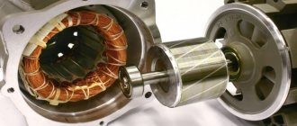
Manufacturing a rotor for an axial shaft
Most often, homemade axial generators are made on the basis of a car hub and brake discs compatible with it (you can use homemade metal discs, as Aleksei2011 did). The scheme will be as follows.
In this case, the stator diameter is larger than the rotor diameter. This allows the stator to be attached to the wind generator frame using metal pins.
Alexei2011
There are studs for fastening the M6 stator (3 pieces). This is for generator testing only. Subsequently there will be 6 of them (M8). I think that for a generator of such power this will be quite enough.
In some cases, the stator disk is attached to a fixed axis of the generator. This approach makes it possible to make the design of the generator smaller, but the operating principles of the device do not change.
Opposite magnets must be directed towards each other with opposite poles: if on the first disk the magnet faces the generator stator with its south pole “S”, then the opposite magnet located on the second disk must face the stator with its “N” pole. In this case, magnets located nearby on the same disk must also be oriented in different directions.
The strength of the magnetic field created by neodymium magnets is quite strong. Therefore, the distance between the stator disks and the generator rotor should be adjusted using a pin-threaded connection.
This is a design option in which the rotor diameter is larger than the stator diameter. The stator in this case is attached to the fixed axis of the device.
Also, to adjust the distance between the disks, you can use spacer bushings (or washers), which are installed on the stationary axis of the generator.
The distance between the magnets and the stator should be minimal (1...2 mm). You can glue magnets to generator disks with ordinary superglue. It is best to stick magnets using a pre-prepared template (for example, made from plywood).
This is what preliminary tests of the generator performed by user Aleksei2011 using a screwdriver showed: at 310 rpm, 42 volts were removed from the device (star connection). One phase produces 22 volts. The calculated resistance of one phase is 0.95 Ohm. After connecting the battery, the screwdriver was able to spin the generator up to 170 rpm, and the charging current was 3.1A.
After lengthy experiments, which were associated with the modernization of the working propeller and other smaller-scale improvements, the generator demonstrated its maximum performance.
Alexei2011
Finally, the wind came to us, and I recorded the maximum power of the windmill: the wind intensified, and gusts at times reached 12 - 14 m/s. The maximum recorded power is 476 Watts. With a wind of 10 m/s, the windmill produces approximately 300 watts.
Wind generator with vertical axis of rotation
In wind generators of this type, the rotating axis of the generator is located vertically relative to the surface of the earth.
Over the years of using devices of this type, various designs have appeared that are combined into groups, these are:
With a Darrieus rotor - the units are equipped with two or three blades curved in the shape of an oval.
The positive features of this design include:
- Independent orientation in relation to air flows;
- Convenient installation maintenance.
- Simplicity of the unit diagram.
The negative ones include:
- There is no possibility to independently spin the blades;
- Significant load on structural elements;
- The blades must be identical and correspond to the specified profile;
- Increased noise level during operation.
- With a Savonius rotor - the units are equipped with blades in the form of cylindrical surfaces.
The advantages of this group are:
- Insignificant wind flows are required to start operation;
- Ability to quickly gain torque;
- Reliability of the design;
- Low cost.
The disadvantages include:
- Low efficiency of devices in this group.
Devices with a Savonius rotor are used when installing combined wind generators; they are used to accelerate units with a Darrieus rotor.
With vertical-axis rotor designs - the units of this group have blades that resemble the shape of an airplane wing and are located vertically, the rotor axis is parallel to the shaft.
In appearance, the units of this group are similar to devices with a Darrieus rotor.
The positive qualities of the devices include:
- Ease of manufacture;
- Ability to quickly increase rotation speed;
- Low noise level.
- Reliability in operation.
- With a helicoidal rotor - units of this group are a more developed version of devices with a vertical axial rotor. The blades have a helicoidal curve shape.
Positive traits:
- Lower loads on structural elements;
- Quick set of rotation speed.
Flaws:
- Increased noise level;
- High price.
- Multi-blade rotor - units of this type are based on a vertical-axis design with an additional outer ring of fixed blades.
Advantages of units of this group:
- Higher efficiency of installations;
- Sensitivity to wind currents.
Flaws:
- High price;
- Increased noise level.
Sun
In the first position is the simplest one, most often called the Savonius rotor. In fact, it was invented in 1924 in the USSR by J. A. and A. A. Voronin, and the Finnish industrialist Sigurd Savonius shamelessly appropriated the invention, ignoring the Soviet copyright certificate, and began serial production. But the introduction of an invention in the future means a lot, so in order not to stir up the past and not disturb the ashes of the deceased, we will call this windmill a Voronin-Savonius rotor, or for short, VS.
The aircraft is good for the home-made man, except for the “locomotive” KIEV at 10-18%. However, in the USSR they worked a lot on it, and there are developments. Below we will look at an improved design, not much more complex, but according to KIEV, it gives bladers a head start.
Note: the two-blade aircraft does not spin, but jerks jerkily; The 4-blade is only slightly smoother, but loses a lot in KIEV. To improve, 4-trough blades are most often divided into two floors - a pair of blades below, and another pair, rotated 90 degrees horizontally, above them. KIEV is preserved, and the lateral loads on the mechanics weaken, but the bending loads increase somewhat, and with a wind of more than 25 m/s such an APU is on the shaft, i.e. without a bearing stretched by cables above the rotor, it “tears down the tower.”
Daria
Next is the Daria rotor; KIEV – up to 20%. It is even simpler: the blades are made of a simple elastic tape without any profile. The theory of the Darrieus rotor is not yet sufficiently developed. It is only clear that it begins to unwind due to the difference in the aerodynamic resistance of the hump and the tape pocket, and then it becomes sort of high-speed, forming its own circulation.
The torque is small, and in the starting positions of the rotor parallel and perpendicular to the wind it is completely absent, so self-spin is possible only with an odd number of blades (wings?) In any case, the load from the generator must be disconnected during spin-up.
The Daria rotor has two more bad qualities. Firstly, when rotating, the thrust vector of the blade describes a full rotation relative to its aerodynamic focus, and not smoothly, but jerkily. Therefore, the Darrieus rotor quickly breaks down its mechanics even in a steady wind.
Secondly, Daria not only makes noise, but screams and squeals, to the point that the tape breaks. This happens due to its vibration. And the more blades, the stronger the roar. So, if they make a Daria, it is with two blades, from expensive high-strength sound-absorbing materials (carbon, mylar), and a small aircraft is used for spinning in the middle of the mast-pole.
Orthogonal
At pos. 3 – orthogonal vertical rotor with profiled blades. Orthogonal because the wings stick out vertically. The transition from BC to orthogonal is illustrated in Fig. left.
Carousel and orthogonal rotors
The angle of installation of the blades relative to the tangent to the circle touching the aerodynamic foci of the wings can be either positive (in the figure) or negative, depending on the wind force. Sometimes the blades are made rotating and weather vanes are placed on them, automatically holding the “alpha”, but such structures often break.
The central body (blue in the figure) allows you to increase the KIEV to almost 50%. In a three-blade orthogonal, it should have the shape of a triangle in cross-section with slightly convex sides and rounded corners, and with a larger number of blades, a simple cylinder is sufficient. But the theory for the orthogonal gives an unambiguous optimal number of blades: there should be exactly 3 of them.
Orthogonal refers to high-speed wind turbines with OSS, i.e. necessarily requires promotion during commissioning and after calm. According to the orthogonal scheme, serial maintenance-free APUs with a power of up to 20 kW are produced.
Helicoid
Helicoidal rotor, or Gorlov rotor (item 4) is a type of orthogonal that ensures uniform rotation; an orthogonal with straight wings “tears” only slightly weaker than a two-bladed aircraft. Bending the blades along a helicoid allows one to avoid losses of CIEV due to their curvature. Although the curved blade rejects part of the flow without using it, it also scoops part into the zone of highest linear speed, compensating for losses. Helicoids are used less often than other wind turbines, because Due to the complexity of manufacturing, they are more expensive than their counterparts of equal quality.
Barrel raking
For 5 pos. – BC type rotor surrounded by a guide vane; its diagram is shown in Fig. on right. It is rarely found in industrial applications, because expensive land acquisition does not compensate for the increase in capacity, and the material consumption and complexity of production are high. But a do-it-yourselfer who is afraid of work is no longer a master, but a consumer, and if you need no more than 0.5-1.5 kW, then for him a “barrel-raking” is a tidbit:
Vertical rotor with guide vane
- A rotor of this type is absolutely safe, silent, does not create vibrations and can be installed anywhere, even on a playground.
- Bending a galvanized “trough” and welding a frame of pipes is nonsense work.
- The rotation is absolutely uniform, the mechanical parts can be taken from the cheapest or from the trash.
- Not afraid of hurricanes - too strong a wind cannot push into the “barrel”; a streamlined vortex cocoon appears around it (we will encounter this effect later).
- And the most important thing is that since the surface of the “barrel” is several times larger than that of the rotor inside, the KIEV can be over-unit, and the rotational moment already at 3 m/s for a “barrel” of three-meter diameter is such that a 1 kW generator with a maximum load of They say it’s better not to twitch.
Video: Lenz wind generator
Wind power plant from a car generator
A popular solution among people who practice making wind turbines with their own hands is to remake a car generator for alternative needs. Despite all the attractiveness of such an idea, it should be noted that a car generator in the form in which it is installed on a vehicle engine is quite problematic to use as part of a wind power plant. Let's figure out why:
- Firstly, the winding of the coils of a standard automobile generator consists of only 5...7 turns. Therefore, in order for such a generator to begin charging the battery, its rotor must be spun to approximately 1200 rpm.
- Secondly, magnetic induction in a standard car generator occurs due to the excitation coil, which is built into the rotor of the device. In order for such a generator to operate without connecting to an additional power source, it must be equipped with permanent magnets (preferably neodymium) and certain adjustments must be made to the stator winding.
Mikhail26
A converted autogenerator (with magnets) has the right to life. I have two of these now. In a wind of 8 m/s with two-meter propellers they give an honest 300 watts each.
Converting a car generator to a wind turbine requires some skill. Therefore, it is advisable to start it with experience in rewinding asynchronous motors or generators with a standard cylindrical stator (both of them, if desired, can be converted into an alternative power plant). Remaking a car generator has its own nuances. It will be much easier to understand them if we turn to the experience of users who have achieved certain success in this area.
Assessment of the feasibility of installation
Before starting to manufacture a vertical wind generator, they study the weather situation in their region and try to determine whether the unit can provide the required amount of resource.
Experts recommend evaluating the following parameters:
- number of windy days - take the average value for the year when the gust exceeds 3 m/s;
- the amount of electricity consumed per day by a household;
- a suitable place on your own site for wind equipment.
The first indicator is learned from data obtained at the nearest weather station or found on the Internet on the relevant portals. Additionally, they check with printed geographical publications and create a complete picture of the wind situation in their region.
Statistics are taken not for one year, but for 15-20 years, only then the average figures will be as correct as possible and will show whether the generator will be able to fully satisfy the household’s need for electricity or whether its power will only be enough to power individual household needs.
If the owner has a large plot of land located on a slope, near a river bank or in open space, there will be no problems with installation.
When the house is located in the depths of a populated area, and the yard has compact dimensions and is closely adjacent to neighboring buildings, it will not be easy to install a vertical model of a windmill with your own hands. The structure will have to be raised 3-5 m above the ground and further strengthened so that it does not fall in the event of a strong gust.
All this information needs to be taken into account at the planning stage to make it clear whether the wind generator can take over the full energy supply or its role will remain as an auxiliary energy source. It is advisable to first calculate the windmill.
Cable twist protection
As you know, the wind does not have a constant direction. And if your wind generator rotates around its axis like a weather vane, then without additional protective measures the cable running from the wind generator to other elements of the system will quickly twist and become unusable within a few days. We bring to your attention several ways to protect yourself from such troubles.
Method one: detachable connection
The simplest, but completely impractical method of protection is to install a detachable cable connection. The connector allows you to untangle a twisted cable manually, disconnecting the wind generator from the system.
w00w00 FORUMHOUSE user
I know that some people put something like a plug with a socket at the bottom. The cable got twisted and I unplugged it from the outlet. Then he unscrewed it and stuck the plug back in. And the mast does not need to be lowered, and current collectors are not needed. I read this on a forum on homemade windmills. Judging by the author's words, everything works and the cable does not twist too often.
Method two: using a rigid cable
Some users advise connecting thick, elastic and rigid cables (for example, welding cables) to the generator. The method, at first glance, is unreliable, but has the right to life.
user343 FORUMHOUSE user
I found it on one site: our method of protection is to use a welding cable with a hard rubber coating. The problem of twisted wires in the design of small wind turbines is greatly overestimated, and welding cable #4...#6 has special qualities: hard rubber prevents the cable from twisting and prevents the windmill from turning in the same direction.
Method three: installing slip rings
In our opinion, only installing special slip rings will help to completely protect the cable from twisting. This is exactly the method of protection that user Mikhail 26 implemented in the design of his wind generator.
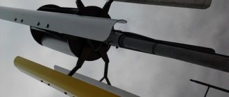
Wind generator installation location
The wind generator described here is mounted on a 4-meter pole on the edge of a mountain. The pipe flange, which is installed at the bottom of the generator, ensures easy and quick installation of the wind generator - just screw 4 bolts. Although for reliability, it is better to weld it.
Typically, horizontal wind generators “love” when the wind blows from one direction, unlike vertical wind turbines, where, due to the weather vane, they can turn and do not care about the direction of the wind. Because Since this wind turbine is installed on the shore of a cliff, the wind there creates turbulent flows from different directions, which is not very effective for this design.
Another factor to consider when choosing a location is the wind strength. An archive of data on wind strength for your area can be found on the Internet, although it will be very approximate, because it all depends on the specific location. Also, an anemometer (a device for measuring wind force) will help in choosing the location for installing a wind generator.
Wind turbine protection from storms
We are talking about protecting the device from hurricanes and strong gusts of wind. In practice, this is implemented in two ways:
- Limiting the speed of the wind wheel using an electromagnetic brake.
- By moving the plane of rotation of the propeller away from the direct influence of the wind flow.
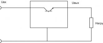
The first method is based on connecting a ballast electrical load to a wind generator. We have already talked about it in one of the previous articles.
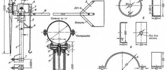
The second method involves installing a folding tail, which allows you to direct the propeller towards the wind flow at nominal wind strength, and during a storm, on the contrary, to move the propeller out of the wind.
Protection by folding the tail occurs according to the following scheme.
- In calm weather, the tail is positioned slightly at an angle (down and to the side).
- At rated wind speed, the tail straightens and the propeller becomes parallel to the air flow.
- When the wind speed exceeds the nominal value (for example, 10 m/s), the wind pressure on the propeller becomes greater than the force created by the weight of the tail. At this moment the tail begins to fold and the propeller moves out of the wind.
- When the wind speed reaches critical values, the plane of rotation of the propeller becomes perpendicular to the wind flow.
When the wind weakens, the tail, under its own weight, returns to its original position and turns the propeller towards the wind. In order for the tail to return to its original position without additional springs, a rotating mechanism with an inclined pin (hinge) is used, which is installed on the tail rotation axis.
The tail rotation axis is set at an angle: 20° relative to the vertical axis and 45° relative to the horizontal axis.
In order for the mechanism to perform its main function, the axis of the mast must be at a certain distance from the axis of rotation of the turbine (optimally 10 cm).
To prevent the tail from folding and falling under the propeller during sharp gusts of wind, limiters must be welded on both sides of the mechanism.
An Excel table with ready-made formulas will help you calculate the tail dimensions and their dependence on other parameters of the wind turbine. In it, the area of variable values is indicated in yellow.
The optimal tail area is 15%...20% of the wind wheel area.
We present to your attention the most common option for mechanical protection of a wind generator. In one form or another, it is successfully used in practice by users of our portal.
WatchCat User FORUMHOUSE
During a storm, you need to slow down the propeller by moving it out of the wind. For example, when the wind is too strong, my windmill tips over with its propeller facing up. Not the best option, because returning to the working position is accompanied by a noticeable blow. But in ten years the windmill did not break down.
Advantages and principle of operation of wind turbines
A modern vertical generator is one of the alternative energy options for the home. The unit is capable of converting gusts of wind into an energy resource. For correct operation, it does not require additional devices that determine the direction of the wind.
A rotary wind generator is very easy to make with your own hands. Of course, he won’t be able to completely take on the responsibility of providing energy to a large private cottage, but he will do an excellent job of lighting outbuildings, garden paths and local areas.
The vertical type device operates at a low height. Its maintenance does not require various devices to ensure safe high-altitude repair and maintenance work.
A minimum of moving parts makes the wind turbine more reliable and operationally stable. The optimal profile of the blades and the original shape of the rotor provide the unit with a high level of efficiency, regardless of which direction the wind is blowing at any given moment.
Small household models consist of three or more light blades, instantly catch the weakest gust and begin to rotate as soon as the wind force exceeds 1.5 m/s. Thanks to this ability, their efficiency often exceeds that of larger installations requiring higher winds.
The generator operates absolutely silently, does not disturb owners and neighbors, does not create harmful emissions into the atmosphere and reliably serves for many years, carefully supplying energy to living quarters.
A vertical wind generator operates on the principle of magnetic levitation. As turbines rotate, impulse and lift forces are generated, as well as actual braking forces. The first two cause the blades of the unit to rotate. This action activates the rotor and it creates a magnetic field that produces electricity.
A wind turbine with a vertical axis of rotation is not inferior in efficiency to its horizontal counterparts. In addition, it makes no claims to the territorial location and works fully in almost any place convenient for homeowners
The device functions completely independently and does not require the owner’s intervention in the process.
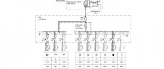
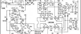
Schemes and drawings
The generator as a device produces alternating current, which must be converted to direct current and brought to the required voltage. If the motor-generator outputs, say, 40 V, then this is unlikely to be an appropriate value for most consumer electronics that consume 5 or 12 volts DC or 127/220 volts AC.
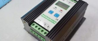
The circuit of the entire installation, proven by time and millions of users, includes a rectifier, controller, battery and inverter. A car battery with a capacity of 55-300 ampere-hours is used as a buffer storage device for stored energy. Its operating voltage is 10.9-14.4 V with cyclic charging (full charge-discharge cycle) and 12.6-13.65 with buffer (portioned, dosed, when you need to recharge a partially discharged battery).
The controller converts, for example, the same 40 volts into 15. Its volt-amperage efficiency ranges from 80-95% - without taking into account losses on the rectifier.
A three-phase generator has the greatest efficiency - its output is 50% greater than that of a single-phase one, it does not vibrate during operation (vibration weakens the structure, making it short-lived).
The coils in the winding of each phase alternate with each other and are connected in series - like the poles of the magnets, one of the sides facing the coils.
Modern household appliances and electronics are capable of operating from 110 volts (American standard for household networks) up to 250 - it is not recommended to give more to network appliances and devices. All converters are pulsed; compared to linear ones, their heat losses are significantly less.
Legal aspects of installing a wind power generator
A wind generator is an unusual property; owning this device is subject to compliance with certain rules and laws. If the device is installed near bridges, airports and tunnels, then the height of the mast should not exceed 15 m. The noise level generated should not exceed 70 dB during the day and 60 dB at night. Protection against TV interference is required. Environmental services should not make claims regarding the creation of obstacles to the migration of migratory birds. It is advisable to conduct legal consultation and have official documents for each parameter before starting construction. The laws do not provide for any taxation for the production of electricity for one’s own domestic needs.
PHOTO: YouTube.comWindmill
Instructions for making a wind generator with your own hands
- Mount the magnets into specially made recesses on the rotor. Use superglue for security.
- Wrap the magnets in paper and fill the remaining free space with epoxy resin.
- Turn the axle on lathe equipment. Attach a steel rod holder to it.
- Make blades from the pipe.
- Attach the generator, blades, rotor and tail to the support rail.
- Install the power unit using a hinged mount.
- Mount the mast into the concrete base and secure with 4 bolts.
- Connect the wire to the shield.
- Connect everything and test to see if it works.
If you feel unsure of your own abilities, buy a household unit. This will also be beneficial. In general, select a model based on your financial capabilities and build it on your summer cottage.
Do this right now and tomorrow you will stop flinching when receiving electricity bills.