Good time! Today we will talk about how to assemble a 220V electricity metering panel. And what is basically needed for this. Let’s say right away that the assembly issue is quite complex, and if you are not confident in your abilities, then it is better not to take on such work yourself, since the price of an error here is fraught with consequences such as a short circuit or fire. At the end, we will provide a diagram in which we will show what malfunctions in the metering panel can cause equipment failure, ranging from heating boilers to LED lamps.
So, let's begin. As the name implies, “metering board”, this board is used to record the electricity you consume. Therefore, it must have a counter, but first things first.
Assembly order
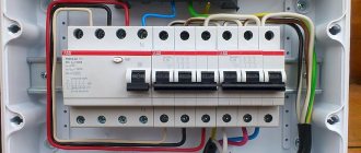
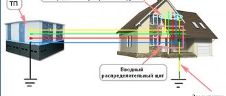
After receiving permission to connect to three phases and technical conditions, we will begin to independently assemble the shield. The input will be mounted in a sealed box, which must be assembled on the outer wall of a private house or pole. It contains a three-phase meter and a circuit breaker, as shown in the photo below:
Near the input we organize a grounding device, according to the rules. The input electricity metering panel will be sealed and there will be no free access to it. Therefore, the first thing you need to do is assemble a three-phase distribution panel yourself, distributing consumers as you wish.
A 5-core cable L1 is connected from the input box to the electrical distribution panel; L2; L3; N; PE, or 4-wire L1; L2; L3; N provided that the TN-CS grounding scheme is used or another grounding device is organized near the panel.
To connect three-phase home equipment, you will need to assemble a shield according to the following diagram:
The assembly of a 380-volt metering board is carried out with a stranded wire, with a cross-section of at least 4 mm and colored insulation. Recommended colors - L1 red, L2 white, L3 black, N blue, PE yellow-green. To correctly assemble a three-phase panel, you need to carefully look at the protective devices on which phase marks are marked for connecting the wires. This diagram shows four-pole RCD protective devices with an additional N terminal; in conventional machines this terminal may not be present. One by one, we begin to connect the devices installed in the panel on the DIN rail, measure the wire from terminal L1 to terminal L1 of the next device, with a margin of 30%, for ease of installation and operation.
We carry out this operation with all terminals, but keep in mind that it is not recommended to cut the sections in advance, because during the assembly process you will notice that the length of section L1 is much shorter than the mounting section L3. It’s even better to assemble the shield using a three-phase mounting bus, which will save space and minimize the chances of getting something mixed up. We separately install the zero bus and the PE bus, which we must connect to the housing of the electricity metering panel.
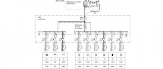
If you don’t have powerful equipment in your apartment or house, you need to assemble a 380V panel in such a way that each phase is evenly loaded with single-phase consumers. You can see an example of such an assembly of a three-phase electrical panel in a private house below:
In this electrical panel diagram, the phases are distributed to a separate load, through single-pole circuit breakers and differential switches. L1, L2 and L3 are evenly loaded by consumers, according to the previously calculated expected load.
It is not recommended to do this - one phase for sockets, another for lighting, a third for any other needs, because
it is important to distribute the load between L1, L2, L3. If one of the phases is overloaded, the voltage drops on it, while at the same time the voltage rises on the free ones
This phenomenon can often be observed in the winter, in the residential sector. If your neighbor in the phase turned on a powerful consumer, the lighting lamps in your house began to glow dimly, and the refrigerator began to hum strainedly. Know this is a drawdown in your phase. And at the same time, other neighbors’ lamps, powered from other phases, begin to glow brightly and explode, equipment burns out, and a fire may even break out.
As for the three-phase load, such a distortion will be fatal for it. To prevent this from happening, when you decide to assemble a shield, additionally install a phase and voltage control relay for a three-phase network. For a single-phase network, connect a voltage relay. You can check the load distribution using a multimeter with a current clamp, which is shown in the photo below.
Well, the last option for assembling a 380-volt electricity metering panel is mixed, when the home electrical network contains both three-phase and single-phase electricity consumers. In this case, you need to assemble the electrical panel as follows:
Selecting the number of circuit breakers
Single-pole circuit breaker
But first of all, you need the box itself (panel) in which you will install everything. It is selected based on the number of circuit breakers (“Automatic Switches”), and how many of them to install is up to you. You can at least install a separate circuit breaker for each socket and switch. But of course this will be unnecessary. It is best to separate outlets and lighting. That is, one machine for lighting and another for sockets. If the consumption is too high, then you can, for example, connect 2 rooms to one pair of machines , and the remaining rooms to another pair. By the word pair, I mean two machines, one for “light” and the other for sockets. If any device in the house consumes more than 5 kilowatts, then it must be connected with a separate line (and, accordingly, a separate machine). These are devices such as an electric stove, electric boiler, etc. It is also recommended to connect the washing machine to a separate line. And, of course, you need to keep a couple of spare machines in case a new consumer appears in the house. At the input, it is also advisable to install a two-pole circuit breaker (double) as well as an RCD and OPS, but more on that later.
Selecting the power of circuit breakers
Various circuit breakers
In the previous article about replacing wiring, I already told you about the choice of wire cross-section and that a 2.5mm² cross-section goes to sockets, and 1.5mm² to lighting. So, the machines are selected based on the wiring cross-section , so that it can turn off before your wire starts to melt from overload. It turns out that a machine with a power rating of 25A (ampere) is installed on a 2.5mm² wire, and with a power rating of 16A on a 1.5mm² wire. Below is a table showing which section it is recommended to install which machine and what is the maximum load of such a wire:
| Section of copper conductors of wires, sq. mm | Permissible continuous load current for wires, A | Rated current of the circuit breaker, A | Maximum current of the circuit breaker, A | Maximum power of single-phase (220V) load KW | Characteristics of household load (220V) |
| 1.5 | 19 | 10 | 16 | 4,1 | Lighting and alarm |
| 2.5 | 27 | 16 | 20 | 5,9 | Socket groups and electric floors |
| 4 | 38 | 25 | 32 | 8,3 | Water heaters and air conditioners |
| 6 | 46 | 32 | 40 | 10,1 | Electric stoves and ovens |
| 10 | 70 | 50 | 63 | 15,4 | Opening lines |
Instructions for assembling a three-phase electrical panel
First you need to get permission to connect to three phases. The installation of the input will be carried out in a hermetically sealed box on the external wall of a private house. It will have a three-phase meter and a circuit breaker installed.
Near the input you must organize a grounding device. The entrance panel will be sealed and free access will be limited. That is why you first need to assemble the three-phase distribution panel yourself.
A 5-core cable L1, L2, L3, N, and PE must be connected to the distribution board. You can also install a 4-core cable L1, L2, L3 and N. This cable can be used if you have a TN-CS circuit. To connect three-phase home equipment, use the following diagram:
The assembly of a 380-volt metering board is carried out with a stranded wire, which has a cross-section of at least 4 mm. Recommended colors are L1 red, L2 white, L3 black N blue and PE yellow-green. To correctly assemble a three-phase shield, you should carefully look at the protective devices. The diagram that we posted above shows four-pole RCD protective devices with an additional terminal N. In conventional machines, this terminal may simply be missing. In the panel, the devices must be mounted on a DIN rail. Before installing wiring, be sure to learn how to mark wiring.
This operation must be performed on all terminals. During installation, please note that it is not recommended to cut the sections in advance. This is because during the installation process you will notice that the length of L1 will be much shorter than the length of L3. It’s even better to assemble the shield using a three-phase mounting bus, which can save space and minimize the chance of getting something mixed up. The neutral and PE bus must be connected to the body of the electrical panel.
If your apartment or house does not have powerful equipment, then you need to assemble a 380V panel. Thanks to this, the phase will be evenly loaded with single-phase consumers. You can see an example of assembling a three-phase electrical panel in a private house below:
In this electrical panel diagram, the phases will be distributed to a separate load through single-pole circuit breakers and differential switches. You should not have one phase go to sockets, the second to switches, and the third to other needs. You need to try to evenly distribute all the loads. If one of the phases is overloaded, then you may notice a voltage drop. This phenomenon can be observed quite often in the private sector. If you are interested, then you can also read about cable wiring.
If your neighbor turns on too much power, then you may see that your incandescent lamps have dimmed. Remember that this process is called phase drawdown. Neighbors who are powered from other phases may experience that the lamps shine too brightly. For a three-phase load, the imbalance will be fatal. To avoid this process, you need to try to install a phase and voltage control relay. For a single-phase network, you can connect a voltage relay. You can easily check the correct load distribution using a multimeter that has a current clamp.
For the last version of the panel assembly, electricity metering at 380 volts is mixed. When there will be three-phase and single-phase electricity consumers in the home network. In this case, you can assemble the shield as follows:
Features of a 3-phase network
The 3-phase power supply system of a private house has the following number of features:
- Both single-phase and three-phase electrical equipment can be connected to the network. So, if it is intended to run a 3-phase device, then it is connected to 3 phases and neutral via the corresponding terminals, and if it is a 1-phase device, then only to one phase and zero. In this case, in the first case, a voltage of 380 V is supplied to the device, in the second - 220 V.
- Not always among the arsenal of home electrical equipment there are 3-phase installations - most often standard single-phase ones. However, assembling a 380 V and 15 kW electrical panel in a private house makes it possible to evenly distribute the load of a large number of simultaneously operating 1-phase devices across all 3 phases. In practice, this makes it possible to use conductors of a smaller cross-section for the home electrical circuit, circuit breakers with a minimum rating and increase overall safety.
- The total power is distributed evenly across all phases. For example, if the sum is 15 kW, then each of them will have 5 kW. In this case, a prerequisite is the installation of only a 3- or 4-pole circuit breaker.
The 380 V electrical panel is based on a 3-pole input circuit breaker Source dc-electro.ru
If the load on any one branch is even slightly exceeded, the power to the entire circuit will be turned off - that is, the house will be de-energized. Therefore, the distribution for each phase should be as accurate and thoughtful as possible.
Requirements for shields
The following requirements apply to electrical distribution panels used in a 3-phase network:
- Conductor protection from overloads and short circuits. Modern panels are equipped with combined circuit breakers. So, if overheating occurs, a circuit release sensitive to thermal changes is triggered, and if there is an instantaneous increase in current parameters, an electromagnetic switch comes into play.
- Ensuring safety from electric shock to people and animals. In most cases, protection is carried out by installing difavtomats or RCDs in the input panel of a private house at 380 volts and 15 kW.
The safety of a 3-phase network is ensured by a residual current device. Source obi.ru
- Limitation of input current characteristics. To ensure that in the event of a sharp increase or decrease in network parameters, the connected electrical equipment is not damaged, a UZM is installed. Using special regulators, the user sets a safe value for network parameters, exceeding the boundaries of which will lead to automatic power off and protect the devices from damage.
Advice! For maximum ease of use and quick decision-making in the event of an emergency, it is better to mark all elements of the electrical cabinet - so that, if necessary, turn off the supply in a specific room or area of the house, as well as to quickly find the reason for turning off the machine. This can be done either using a regular marker or by gluing signed signs onto tape.
Differences in the assembly of 1- and 3-phase panels
Unlike 1-phase networks, 3-phase networks allow the consumer to receive more power from the electricity supplier, which makes it possible to connect a much larger load. However, this entails high costs and the need to strictly adhere to the rules for assembling the shield.
Proper distribution of the load across phases is the main requirement for assembling a 3-phase panel Source elektroznatok.ru
First of all, in order to competently and safely assemble a three-phase panel rated 380 V and 15 kW in a private house, it is necessary to take into account the rule of load distribution across phases. If in a 1-phase network it doesn’t matter how many and in what sequence you connect devices - as long as the amount of load does not exceed the established limit, then in a 3-phase network the uniformity of connecting devices across all phases is very important.
Otherwise, if most of the devices are connected to one phase, and the other two are left “as reserves,” a voltage imbalance will occur. As a result, the current value in the overloaded phase will decrease, and in the free phase it will increase by several tens of volts. At a minimum, this will lead to the machine turning off, and in the worst case, an accident on the line and in neighboring houses.
See also: Catalog of companies that specialize in electrical work of any complexity
Electrical 380V electricity metering panel for a private house with a 220V socket
In this electrical panel diagram, there is additionally a modular 220V socket (number 7) with an individual protection device - difavtomat (number 8), which combines a circuit breaker and a residual current device. The rating of the RCD must be higher than that of the circuit breaker, for example 40A, leakage current 100 or 300 mA.
Electrical metering panel 380V, with modular socket and automatic circuit breaker, TT grounding
Following this example, where the outlet is protected by a residual current circuit breaker, you can install any other modular equipment, contactors, transformers, etc. to the electricity metering panel, if necessary.
Let me note again that under each diagram there are links, by clicking on which you can read the details, find out the equipment used, and ask questions.
Otherwise, here are the main options that are used when connecting private houses and garden houses to the power grid. And most importantly, such electrical panels are successfully accepted by regulatory authorities and put into operation.
Build process
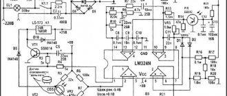
Now it’s time to figure out how to assemble a 220 V metering panel. You only need to carry out the assembly according to the diagram. We remind you once again that if you do not know how to assemble, then it is better to turn to professionals. Below is an assembly diagram that includes an RCD and an OPS.
Electricity metering panel diagram with RCD and OPS
The installation should begin with the introductory machine. Then, in parallel with the introductory machine, you need to install an alarm system. This device must be additionally grounded. Then the phase and neutral wires will go to the meter, and from the meter to the RCD. From the RCD, the phase will be connected through all groups of machines, and the “zero” wire goes to the zero bus. Groups of machines can be connected to each other by a special bus or jumpers. All that remains is to connect “BA” with the power wire.
Some useful tips for assembling a shield
When assembling an electrical panel, it is necessary to use only high-quality and reliable electrical products
You should not pay attention to cheaper Chinese analogues; personal safety is much more important
To connect wires to machines, it is best to use special lugs for crimping. Of course, then you will have to purchase pliers with which crimping is performed, but their cost is not too high.
The use of insulating tape is no longer relevant; many electricians use exclusively heat-shrinkable tubing. This consumable is convenient and reliable, and it is not necessary to purchase a hair dryer; you can use an ordinary lighter.
For ease of use, all elements of the electrical cabinet must be marked. Only then will it be possible to quickly and easily turn off the voltage in a certain room. You can make notes on the body of the device or make small signs and attach them to the product with tape.
Installation work
Step 1 – Choose a location
First you need to decide where to make the grounding loop
The importance of this stage is very high, because The safety of using the system depends on the choice of grounding location in a summer cottage
If a breakdown of the electrical wiring occurs, as a result of which the protection is triggered, then there should be no one in the place where the pins are located. The presence of a person or animal at the site where electricity is discharged into the soil can cause death. That is why the location of the electrodes is chosen taking into account the fact that no one will be there. It is best to place the outlet along the fence behind the house, at a distance of no more than 1 meter from the foundation of the building. Additionally, it is recommended to make a low fence or border to fence off the unsafe area.
If you do not want to spoil the landscape design of the area, we recommend organizing a grounding system for your residential building under boulders or some kind of voluminous garden sculpture. In this case, no one will be able to be in the danger zone and nothing will harm the beauty of the garden area!
Step 2 – Excavation
For example, let's look at how to properly ground a private house with a triangle according to the scheme we discussed above. At this stage, you need to dig a triangle with sides of 1.2 meters with a shovel (the most optimal distance between the corners). The depth of the trench should be from 50 to 70 cm. The same trench should be dug to the porch of the house.
Electricity metering board diagram 380V for a private house 15 kW
When connecting a private house to the power grid, you will definitely need to obtain technical specifications for connection from the electricity supply company (Mosenergo, Lenenergo, Sverdlovenergo, etc., depending on the region). It is this document that contains the main characteristics of the electrical network available to you, including the requirements for the electricity metering panel.
In this article we will examine in detail the diagram of a typical metering panel, as well as its modifications, which require collecting the requirements of technical specifications.
In such cases, the standard network parameters for connecting a private home are:
— 3 phases
— Voltage: 380V
— Power allocated: 15 kW
— Input cable: SIP 4-core (3 phase conductors and PEN)
I would like to note that one of the main tasks of technical specifications is not only to ensure the safety of the electrical installation, but also to prevent the possibility of theft of electricity by consumers.
That is why all protection or switching devices in the electrical panel located before the electric meter must be protected from the possibility of illegal connection. Usually they are hidden in separate boxes, which are sealed when connected.
In addition, the technical specifications require that the metering board be placed in a place accessible for inspection - on the border of the site, on a lighting pole or fence.
Most often, such external panels are used exclusively for accounting, without additional capabilities, and provide only basic functions. The main distribution board (PDB), in this case, is installed inside the house, where all consumers are divided into groups, the load is distributed, the appropriate automatic protective equipment is installed, etc.
All the diagrams presented below will be designed for the two most popular grounding systems in private homes, TT and TN-CS. Under each connection option there will be links to step-by-step assembly instructions, with detailed comments.
If you have not decided which grounding system to choose, the following information will help you:
TN-CS is the grounding system recommended by the rules. It has a number of disadvantages; it is worth using it if you are confident in the condition of the electrical networks suitable for the house, if they are new enough and regularly maintained.
TT is a relatively safer system. The main disadvantages include only the high costs of installing protective equipment and installing a ground loop, as well as regular maintenance. Which, for safe operation, must always be maintained by you in working condition.
You will learn more about the differences in the design of grounding systems in one of the following articles. Subscribe to our VKontakte group and stay tuned for new materials.
Metering board or “box with meter”?
The power supply to a house, apartment, cottage or future construction site begins with the electricity metering panel. This is an electrical panel with the help of which connection to the electrical network is made, metering of consumed electricity, distribution of electricity and preliminary protection. The design of these electrical panels contains no more than 10-15 elements, but 90% of the panels are designed and assembled incorrectly, and besides, their use is dangerous. This applies not only to panels assembled by skilled electricians, but also to factory-made metering panels. Here is a classic example of a factory-made product that was made in violation of regulations and is potentially dangerous to your life. Such shields should be sold exclusively in the “couch” store.
You may ask, how can this be?! After all, the electricity supply organization accepted the metering board and sealed it!
The answer is simple. Firstly , the balance limit is located at the terminals of the input machine, so you are responsible for everything that is inside the shield. Secondly , when accepting the electrical panel, the connection of the electric meter is checked, i.e. so that it would not be possible to connect bypassing it, simply so that electricity would not be stolen. The rating of the input circuit breaker is also checked, which limits the power consumption of electricity. That’s why the terminals of the input circuit breaker and the meter are sealed. Networkers are not interested in everything else.
Unscrupulous manufacturers take advantage of the lack of awareness of buyers in the field of electrical installation rules (PUE). Knowing that when choosing a metering board, the consumer will choose the one that is cheaper from several options, since he does not see and cannot understand the difference between the electrical panels.
I copied photos of several metering panels from the Internet and all of them turned out to be in violation. Most likely, you have it installed or you will purchase exactly one of the samples .
Let's look at typical mistakes.
Mistake #1.
As a rule, connecting a house to the electrical network is done using a self-supporting insulated wire (SIP). The SIP, in turn, is inserted into the switchboard and connected to the input circuit breaker of the metering panel. At this stage, the first serious mistakes are made.
The SIP section, which is located in the switchboard before the input machine, is the most unprotected part of the metering switchboard.
If the insulation of the self-supporting insulation wire is broken and it is shorted to the panel body before the input circuit breaker, the protection will not work, since the water circuit breaker is located higher, and such an accident is not visible to the substation, due to the small currents for it. As a result, the shield body will be energized or simply burn out. Touching such an emergency shield is deadly.
How can such damage to SIP occur? The SIP is inserted into the panel body through a hole, the edges of which are sharp; they can damage the insulation, especially if this is not done carefully. Of course, rubber seals are included with the housing, but their task is to protect against splashing water and that’s all.
You can also find something like this.
To protect the SIP, it is necessary to use plastic penetrations, which are purchased separately. The installation of self-supporting insulated wires in the switchboard body up to the input circuit breaker must be done in corrugation.
Mistake #2.
The second and most common mistake is how the SIP is connected to the input machine of the metering board. Everywhere this is done simply, the wire is protected and clamped into the terminal of the input machine, and an inexpensive machine with square terminals.
This is absolutely impossible to do. A rectangular terminal cannot completely compress a round SIP wire, and since aluminum has the property of fluidity, over time this connection weakens and begins to heat up.
As a result, the voltage in the house jumps, and then the machine breaks down.
There are hundreds of such examples. Regular tightening of the terminals of the machine is required, but this is impossible to do, because... it is sealed.
A half-measure is to use machines with semicircular terminals and then stretch them for several days before sealing, but the problem still cannot be completely solved.
SIP is a stranded aluminum wire. It cannot be connected without first terminating with a lug.
There are special lugs for connecting self-supporting insulated wires to circuit breakers of the NShA or NShAL type.
It looks like this:
Under no circumstances should you crimp SIP lugs designed for copper wires, even if they are tinned.
It is very common to find circuit breakers with copper terminals. They also cannot be used to connect SIP. Copper and aluminum are not compatible in direct electrical contact; they form a galvanic couple.
Passing an electric current through such a connection will cause the process of electrolysis. Both metals will begin to deteriorate at the point of contact, which will lead to heating and complete failure of the connection, ultimately the machine will burn out. And even if you have an input machine of a famous brand with copper terminals installed in your metering panel, it will fail in the very near future.
Mistake #3
The choice of an input circuit breaker usually involves selecting its rating according to the technical specifications, thereby limiting the maximum power consumption.
But there is another important parameter that the average user will not pay attention to. This is the rated breaking capacity of the circuit breaker, i.e. the maximum short circuit current that the machine is capable of turning off.
To determine the short circuit current in your electrical network, you need to make special measurements. But since no one does this, it is recommended to install circuit breakers with a rated breaking capacity of 6000 A at the input.
According to GOST 32397-2013 Distribution panels for industrial and public buildings. General technical conditions. Clause 6.6.6: The breaking capacity of protective devices installed at the inputs of the panels must be at least 6000 A for rated currents up to 63 A and 10,000 A for rated currents up to 125 A.
But in life everything is different. Automatic switches with a breaking capacity of 4500 A are cheaper, so they are almost always installed in order to save money.
By the way, in the European Union the use of circuit breakers with a rated breaking capacity of less than 6000 A is prohibited.
Mistake #4
Very often you can find metering panels in which the connections are made with wire, beautifully laid and bent at right angles.
The sight of such a shield should alert you. This is what manufacturers do who want to save money and use single-core wire during assembly. For connections inside the switchboard, it is necessary to use an installation stranded wire, for example, brand PV3, which meets the requirements for flexibility for installation. The use of a single-core wire itself is not a critical mistake, but when connecting the switchboard, upgrading it, or replacing components, you will encounter serious difficulties. In addition, there is a risk that the wire will break at the bend and the connection will be broken.
Mistake #5
An error that occurs almost always is that the SIP neutral conductor is connected to the metering panel according to the “zero to meter” principle.
You can't do that. And there are several serious reasons for this.
The neutral conductor also performs a protective function and SPECIAL measures must be applied to it to ensure its reliable mechanical connection.
Many people believe that it is the phase conductor that must be connected reliably. This is not entirely true. Of course, the connection of the phase conductor must be of high quality, but the “burning out” of the zero, the break of the PEN conductor or its poor connection leads to more serious accidents: the network voltage can reach 380 volts, a dangerous potential appears on the housings of household appliances and the likelihood of electric shock to a person. In this case, the RCD will not trip when a person touches the body of the device, which is energized. In the article “ RCD and grounding ” I gave an example of the consequences of a zero violation.
The neutral conductor of the SIP must be connected in the metering panel through a feed-through terminal, which provides maximum mechanical strength and reliability of the connection, without breaking the neutral conductor of the SIP.
A neutral conductor connected directly to the meter is a critical mistake ; you cannot do this, no matter what anyone tells you. You will not be able to control and maintain the connection of the SIP conductor in the meter under the seal. This is a matter of your safety!!!
Mistake #6
This error is an excellent example of what not to do, and speaks of the illiteracy of the shield manufacturer and its attitude towards you and your safety.
To connect power tools during construction, a modular socket is often installed in metering panels. It is protected by a circuit breaker and EVERYTHING!!!!!
According to the Rules for the Operation of Electrical Installations: clause 7.1.71. To protect group lines supplying plug sockets for portable electrical appliances, it is recommended to provide residual current devices (RCDs).
clause 7.1.72 If the overcurrent protection device (circuit breaker, fuse) does not provide an automatic shutdown time of 0.4 s at a rated voltage of 220 V due to low values of short circuit currents and the installation is not covered by a potential equalization system, the installation of an RCD is mandatory.
The use of an RCD in the metering panel to protect the outlet line is strictly MANDATORY. During construction, there is a high probability of damage to the power cable, tool insulation and, as a result, leakage current. An RCD with a differential operating current of no more than 30 mA is the only human protection in this case.
Mistake #7
One of the most difficult errors to understand looks like this:
It is accepted by 99.99999% of manufacturers. Everything seems to be right, but it’s just wrong. And this is not easy to understand.
The grounding terminal of the modular socket in the metering panel CANNOT be connected to the PEN conductor of the SIP.
This will seem extremely strange to you. It is generally accepted that grounding is protection. And again, not much is wrong.
It's all about the PEN conductor and the shortcomings of the TN-C or TN-CS grounding systems, and this is how most houses, cottages and summer cottages are connected. In the event of an accident on the line, “burning out” of the zero, poor-quality connection of the PEN conductor, a dangerous potential may appear on the grounded housings of electrical appliances. High touch voltage is generated between the body of the electrical appliance and the actual ground on which you are standing, which is extremely dangerous!!! Protection in this case is only a potential equalization system, which cannot be done on the street unless you roll out a grounded chain-link mesh over the entire area.
For temporary power supply to a construction site, it is necessary to use a TT grounding system. The housing of the electrical consumer must have independent grounding from the supply network. The use of RCD is strictly MANDATORY !!!!!
As a conclusion. You cannot buy a “standard” metering panel until you have decided how you will connect the house to it and how the grounding system will be installed. Otherwise, you will have to redo it, and it will cost the same as a new shield.
That seems to be all for today!
If you are planning to assemble a switchboard yourself and do electrical work in your house or apartment, we are ready to make a project for you. example project
Electrical design. Assembly of electrical panels for houses and apartments. Tel. 5 Email: [email protected]
DIY installation and installation
First you need to select an electrical panel. To do this, you need to decide on the type of shield. It is recommended to install hidden panels with hidden wiring; with open wiring, it is better to install a hinged panel.
If the apartment does not have a special niche for installing a built-in shield, then you will have to do it yourself, which creates additional difficulties, but such a shield will be well camouflaged. It is much easier to install a wall-mounted distribution panel in an apartment; all you need to do is secure it with several screws, but it does not always look good in the interior.
The next stage depends on how many groups all electricity consumers were divided into at the stage of developing the panel diagram. The number of machines used, as well as the size of the housing where they will be installed, depends on the number of zones.
The case should be selected with a reserve for the number of installed machines, this will save money if you have to upgrade the power supply system. Before installing the shield, you must select its location in the apartment.
The shield should be located in an easily accessible place at a height of 1.5-1.7 meters from the floor level, so that it is not blocked by furniture or doors. The location for placing the shield is selected only once, so it is worth choosing it responsibly.
You should also consider how other pieces of furniture and interior will be placed. If a hidden type switchboard is installed, then it is necessary to select a place where a niche can be built for it.
The following actions must only be carried out when the power supply is turned off. After turning off the electricity, you should insert the cable into the housing through the cable entries, after removing the plugs.
At this point, the installation of the electrical panel is completed; the next task is to install and connect the machines.
We invite you to watch the video - recommendations for installing a built-in cabinet for an electrical panel and how to properly assemble an electrical panel in an apartment with your own hands from a generalist:
Installing an electrical panel is not difficult; it can be done independently. You just need to understand its structure, comply with all the requirements of GOST and PUE, as well as electrical safety rules. And after installation, check whether all elements work correctly.
Nuances of grounding a private house
There are several options for arranging a ground loop. The specific method is selected taking into account the type of soil on the site and the characteristics of the house. Regardless of the chosen method, it is recommended to make grounding electrodes from pipes, one of the ends of which is pre-flattened to a point.
On the lower section of each pipe (the length of the section should be about 50 cm), 10-15 holes with a diameter of about 5-7 mm are made randomly.
In hot weather, it is recommended to pour a saline solution inside the grounding pipes. To prepare it, just dissolve half a pack of salt in a bucket of clean water. This solution will help maintain resistance at a normal level.
The grounding bars also remain the same regardless of the method chosen. You should refrain from using galvanized steel to create metal bonds - the material will very quickly lose its performance properties.
First step. Calculate the contour. To do this, you need to find out the soil resistance value in your area. Find out this information in the relevant reference literature or local services. The same service can give you recommended circuit parameters. This will save you from unnecessary hassle, because the calculation formulas are quite complex and voluminous.
Second step. Choose a suitable location for the circuit. Install the circuit in some place that is rarely visited, the minimum distance from the foundation of the building is 100 cm.
Third step. Prepare the electrodes. They can be made from steel angles. The minimum width of the product is 5 cm, the optimal length is 250-300 cm.
Fourth step. Dig a square or triangular hole about 100 cm deep. The electrodes will be placed in the corners of the pit. Therefore, select the depth and width of the pit so that the distance between the installed electrodes is equal to the length of these products.
Fifth step. Drive the prepared electrodes into the corners of the dug hole. A sledgehammer will help you with this.
Sixth step. Weld a strip of metal to the electrode pins. The welded connection must be reliable and of high quality. Be sure to treat the welding areas with an anti-corrosion compound, for example, bitumen mastic.
Seventh step. Pull the metal strip to the input shield. Next, you will need to connect a ground bus to the strip.
If it is not possible to use a full bus, connect a high-quality copper wire to the metal strip. The cross-section of this wire must be at least 10 mm2. Use a bolt and nut to secure the wire. Treat the connection point between the metal strip and the copper wire with an anti-corrosion agent.
Eighth step. Fill the hole. Firmly compact the backfilled soil.
Some useful tips for assembling a shield
When assembling an electrical panel, it is necessary to use only high-quality and reliable electrical products
You should not pay attention to cheaper Chinese analogues; personal safety is much more important
To connect wires to machines, it is best to use special lugs for crimping. Of course, then you will have to purchase pliers with which crimping is performed, but their cost is not too high.
The use of insulating tape is no longer relevant; many electricians use exclusively heat-shrinkable tubing. This consumable is convenient and reliable, and it is not necessary to purchase a hair dryer; you can use an ordinary lighter.
For ease of use, all elements of the electrical cabinet must be marked. Only then will it be possible to quickly and easily turn off the voltage in a certain room. You can make notes on the body of the device or make small signs and attach them to the product with tape.
What and how to ground
First group . On the back wall of these devices you can find a special terminal, usually a screw terminal, for separate (direct) grounding of the housing.
Most likely, there will be no mention of it in the instructions for electrical appliances, since its presence automatically transfers the device from the class of household to industrial devices.
But despite this, many manufacturers place it on:
- Washing machine (sometimes dishwasher). It definitely needs to be grounded through a Euro socket, since it has a large electrical capacity and is most often installed in a damp room.
- Microwave. The working source of wave radiation in it is a powerful magnetron, and even with minor wiring defects or poor contact in the socket, it is capable of breaking through.
It is not necessary to trust the installation and connection of a power outlet for an electric stove to specialists; the main thing is to have detailed instructions on hand that will help you figure out what and how to do.
You can learn more about installing and connecting an electric meter by reading this article. After this, you can connect an electric meter with one or three headlights yourself.
Second group . For safety reasons, it is advisable to ground them.
- Induction hob (electric hob) and electric oven. The internal wiring in them operates at high temperatures, and the power is quite high.
- Desktop computer. If you ground the computer's power supply directly (at any screw on the rear panel), this will eliminate not only periodically occurring floating potentials, but also some “glitches” of the computer. Even the Internet speed may increase.
- Hydromassage boxes (especially with steam generators). Manufacturers from China did not bother to worry about safety, so it must be grounded directly from any metal fastening under the pallet.
Outdoor panel 15 kW
Street switchboard for connecting a house or plot to a 380 to 15 KW network
Comprises:
- Housing ShchuRN 3-2 IEK IP 54 (2 doors) - 1 piece
- Automatic switch ABB sh202l C25 3P – 2 pcs.
- Automatic switch ABB sh201l 1p C16 – 1 piece
- Automatic switch ABB sh201l 1p C10 – 1 piece
- Din rail socket – 1 piece
- Meter Mercury 231 AM 01 2022 (single tariff) - 1 piece
Everything is collected and connected.
You can add a wire for connection; punctures and anchor hangers are not included in the price.
Price of the assembled cabinet: 9850 rubles.
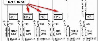
We offer a 15 kW switchboard with a metering device Matrix NP73E.2-12-1, which is a multifunctional system with a multi-tariff electricity metering function (up to 6 time tariffs are available with the ability to set workdays, weekends and special days). When using this metering device, the standard delivery set of the switchboard also changes, where 25 ampere circuit breakers are NOT used, but AB or HV C50, C63 are installed, because there is no need to limit the consumer on how exactly he should receive 15 kW, in 3 phases, in each specific phase, etc., but not exceeding this value.
Shield elements
A standard 3-phase 15 kW electrical panel includes the following components:
- Counter. The optimal solution is an electronic model. The device is characterized by high measurement accuracy, durability and ease of use. Basic information is displayed on a digital display. In this case, programming for specified tariffs is possible.
Electronic meter gives more accurate readings of electricity consumption Source discount-electro.com
- Electrical cabinet Selected according to size and expected number of elements placed in it. Mandatory requirements are minimum dimensions 450 x 400 x 150 mm, metal wall thickness from 1 mm, dust and moisture protection level from IP 54. Additionally, a DIN rail may be present for ease of installation, a lock and a viewing window for viewing information from the meter display.
- Introductory machine. In the input distribution device (IDU) or switchboard of a private house with a network of 380 V and 15 kW, it is necessary to install an input circuit breaker with three poles - due to the connection of 3 phases.
- RCD. To protect against electric current breakdown, a residual current device is installed on the body of the electrical appliance.
- Circuit breakers. They are selected based on the power and number of consumers combined into one branch.
- Voltage relay. It is not mandatory, but if necessary, it reliably protects household electrical appliances from power surges in the network. There are different modifications of the device - UZM for overvoltage protection, SPD against lightning discharges.
The voltage relay protects electrical appliances from voltage surges in the network Source 220-volt.ru
- Network electrical characteristics meters. Also refers to additional elements of the shield. Designed to measure voltage and current.
Selection of circuit breakers is carried out in accordance with the load of the consumer or their groups. For the case under consideration, when the power of electrical appliances in a private house should not exceed 15 kW, the total current will be no more than 68 A, and for each individual 220 V branch the rating of the input panel should be no more than 23 A, or rounded 25 A.
Often, a separate circuit breaker is installed for a separate group of consumers, for example, lamps. In this case, its amperage is 6-10 A. For branches with a power load, its value should be at least 16 A, and in some cases 25 A. Switching on one or more powerful electrical appliances (such as a hob with a power of 6-8 kW ) can easily turn off a machine with a lower nominal value, since it will perceive this event as a short circuit.
The machines are selected according to the number of connected phases and load limit Source 220pro.ru
Sequence of correct installation of an electrical panel
To ensure that the electrical panel in your home is installed correctly, you should use only high-quality electrical products, as well as consumables. Only after installation is completed, operating voltage is supplied to the panel.
The correct assembly of a three-phase electrical panel has the following sequence:
Installation of an introductory machine. The device rating must cover the maximum power consumption. Since 3 phases will be brought into the house, the voltage between them will be 380 V, it is necessary to install a three-pole circuit breaker. To save money, it is not recommended to install 3 single-pole circuit breakers and connect them with a special strip. The input machine is installed in the upper left corner of the shield and is marked accordingly. After the introductory machine, it is necessary to install an RCD. The rating of the device must correspond to the rating of the input switch
You should also pay attention to the cut-off current - the lower this indicator, the faster the RCD will turn off the network. There are differential circuit breakers that include protective functions against short circuits and shutdown of the network when a leakage current occurs (RCD and standard switch)
It is easier to use such a product, but its cost is quite high. To the right of the RCD, at a short distance, a zero bus is mounted. Modern busbars provide a plastic dielectric between the copper strip and the shield body. This is done so that if the zero burns out and a phase gets on it, the electrical panel does not end up under life-threatening voltage. Measuring instruments and voltage relays can also be placed on the strip with the input circuit breaker, RCD and zero bus. If you install a voltmeter and an ammeter in a three-phase network, then you must select products that display both linear and phase loads. And also capable of showing data on each phase separately. The lower DIN rail contains automatic switches for power and lighting lines. In order not to get confused and not constantly look at the rating of the machines, lighting line products should be located at a short distance from the power switches.
After assembling the shield, you can mount it to the wall and connect the wires from consumers to the machines. An example of an electrical panel diagram, the number of machines can vary depending on the wishes of the owner.
If the electricity metering panel with a voltage of 380 V is not located on the street, then it is first installed in front of the input machine.
But installing a device to monitor electricity consumption in the house is inconvenient, so inspectors (to save time and the absence of owners) must take readings on the street. No tags for this post.
Counter selection:
Meters are electromechanical and electronic. Electromechanical meters have a mechanical counting mechanism.
Of course, they are different from their disc-based predecessors. Now the disk has replaced the LED indicator. When this device is disconnected from the network, all readings remain on the display. The electronic meter has a liquid crystal display on which readings are displayed. The error, like that of a mechanical analogue, is within 1%. This meter differs from a mechanical meter in that if it is disconnected from the network or the device breaks down, you will not be able to see the readings. Although electronic meters have more advanced functionality. In addition to the consumed energy, it can show the amount of active and reactive energy and much more (depending on the model). Also, many models are equipped with a function for remote transmission of readings.
In addition, meters are divided into single-tariff and two-tariff. Single-tariff meters count electricity at one tariff, that is, at a daily rate, and you pay a certain amount for each kilowatt. In most cases, such meters are equipped with a mechanical counting system, but there are exceptions (that is, there may be an electronic one).
A two-tariff meter counts electricity at 2 tariffs. Day and night. The day rate is considered the same as for a single tariff, but the daily rate runs from 8:00 to 23:00. The night rate starts from 23:00 to 8:00, but you will pay almost half as much for it. But such a device costs twice as much.
The accuracy class is an indicator of the error of the electric meter. Now new models come with accuracy class 2 and higher, which is allowed in any electrical network. So you shouldn’t focus on this parameter.
Counter sizes
The size of the counters can also be different. There are big and small ones. Quality has nothing to do with size. Large counters require a separate space in the drawer (there are special places in the drawer reserved for this). Small ones are installed in the same way as automatic machines and do not require a specially designated space for themselves.
Purpose of the product
Electrical energy goes through several stages before reaching the consumer: generation and transportation along power transmission lines. Initially, electricity enters the panels, after which it is redistributed. At the same time, the installation of protection systems necessary for possible emergencies and incidents is carried out. Panels are used in manufacturing industries, installation is carried out in residential buildings or public premises.
The main purpose of the cabinet is the reception and subsequent distribution of electrical energy. It also has the function of protecting lines from possible overloads and short circuits. Structurally, the product contains the following elements:
- a protective plate made of plastic or metal with switches attached to it;
- devices for calculating energy consumption;
- input machine
Equipment installation is carried out:
- inside buildings and structures;
- on open air.
The panels are designed for standard network voltage 220 V or 380 V.
Electricity metering cabinets are manufactured in a simple design and are used to receive and transmit electricity for the operation of household appliances, sockets and lighting devices. The purpose of shields is expanding, and there is a need to manufacture more complex structures. Through one panel, electric current can be distributed to one apartment or an entire house.
Introductory board on a pole
I agreed to double the capacity. As a result, the agreement with Energosbyt will include an 8 kW input per phase. The input to the house will be laid with a VVGng 3x16 cable in a technical HDPE pipe. Grounding using the TN-CS system.
I was prohibited from altering the entrance cabinet myself, citing the fact that the switchboard would not be accepted and this alteration should be carried out by an electrician...
For the switchboard we purchased: - a 40A input circuit breaker from Legran - a 300mA selective RCD from ABB - a 40A home circuit breaker from ABB - a 25A circuit breaker from ABB for an additional panel on the site (for welding, etc.) - a distribution block RBP-95 for organizing PEN branching - M10/10 terminal for the output of the ground wire for the cable, which will subsequently be connected to the 25A machine - installation was carried out with PV3 wire 10 squares in double insulation.
The counter remains the same - Mercury 200.02
The cable for connecting to the pole was laid in advance and was waiting in the wings. A trench was dug to the pole into which the cable was laid. On top, for protection, I laid special slabs so that in the future I would not break it with a crowbar or shovel. I talked about these slabs here.
I put a metal pipe on the HDPE pipe, which I had previously painted gray.
In the metal shield, using a “cricket” (a device for cutting metal with a drill), I widened the holes for the seals. Using a stepped drill, an additional hole was made for entering the SIP cable. They did not put an oil seal under it - the shield is so not airtight that there is no special meaning in it. The hole and corrugation were processed so that the cable was not damaged by the edges.
The diagram of the shield on the pillar turned out like this:
Since three modules were used from ABB, I used a regular bus to connect them. This made the installation compact and there was no need to fuss with the cable to connect them. The only thing is that when using the bus, the cable entry into the RCD had to be done from below, and not from above. But this is not critical - you can do it this way.
The RBP-95 block was used in order not to tear the PEN cable, but simply pass it through, cutting off the insulation. The ground connection was made with a crimped conductor of PV3 wire 16 squares. It was crimped with a manual hydraulic press from the KVT PGR-70. It was fastened with M8 bolts directly to the RBP distribution block -95 — the photo shows the mount.
Since the old shield was used - the one that had already been on the pole, for internal peace and from the “pioneers” it was decided to make an internal opening/closing door from duralumin.
I had a scrap of duralumin, as well as corners, which I attached with rivets to the inner side surfaces of the cabinet, 2.5 cm from the edge.
It turned out that the door is located slightly ABOVE the machines, but this does not interfere with their control. It turned out that the 3x16 input cable is so “oaky” that it was not possible to press it additionally so that the homemade plastron door could be lowered closer to the machine.
Well, not scary...
Riveted corners measuring 20x40mm. On the left side of the corner, before installing it in the cabinet, I riveted another corner - a little smaller in size so that the lock would close normally - so that the tongue from the lock would fit snugly.
Here in the photo you can see how the second corner is attached.
On the right side, I riveted a couple of hinges to the corner and already attached a duralumin plastron door to them:
Before installing the corners, I moved the meter to the right - closer to the input machine, so that the corner on the left did not overlap the meter display. From the RBP-95 block, I brought out a 10-square wire to the M10/10 terminal to connect the ground of the cable that will be connected to the B25A machine.
Finally, I pasted a sticker:
To re-ground, I drove a 63x63 by 2m corner next to the pole and connected it to the existing one. History is silent about the depth to which the old corner was hammered. Accordingly, the fastenings were moved to the new corner.
All that remains is to make a more or less normal fastening of the pipe to the pole and ground the panel door.
The cable will enter the house into this distribution panel:
Subsequently, additional grounding of the cabinet doors was done - both main and additional.
www.snthouse.ru