On the blog we have already looked at various ignition systems, in particular contactless ones, in which the mechanical breaker in the distributor is replaced by a tricky sensor. Let's talk about it, about the Hall sensor, that's what they call it. The Hall sensor, its operating principle is that it provides a cutoff at the desired point for igniting the working mixture in the cylinder, but let's take it in order.
[contents]
What is a Hall sensor in a car
A hall sensor is a small device that operates on an electromagnetic principle. Even old cars from the Soviet automobile industry have these sensors - they control the operation of the gasoline engine. If malfunctions appear in the device, the engine will, at best, lose stability.
They are used to operate the ignition system, phase distribution in the gas distribution mechanism and others. To understand what malfunctions relate to sensor failure, you should understand its structure and operating principle.
Benefits of the contactless circuit
How is a contactless ignition system useful, besides, in fact, the absence of those same ill-fated contacts?
It turns out that its use helps increase the power of power units, reduces the amount of harmful emissions into the atmosphere and even reduces fuel consumption.
All this, as experts say, became possible thanks to a higher spark generation voltage than in older systems, which reaches 30,000 Volts.
These goodies, by the way, encourage some drivers to change old contact circuits to contactless ones. Moreover, this is quite simple to do and many car owners do this kind of minor tuning on their own.
Dear readers, as we can see, the non-contact ignition system, the operating principle of which we tried to study today, has become the next step towards circuits of a qualitatively new level, with more reliable and durable components.
Where is it located and what does it look like?
The Hall effect has found application in many car systems, such as:
- Determines the position of the crankshaft (when the piston of the first cylinder is at the top dead center of the compression stroke);
- Determines the position of the camshaft (to synchronize the opening of valves in the gas distribution mechanism in some models of modern internal combustion engines);
- In the ignition system breaker (on the distributor);
- In the tachometer.
During the rotation of the motor shaft, the sensor reacts to the size of the teeth slots, which generates a low voltage current that is supplied to the switching device. Once in the ignition coil, the signal is converted into high voltage, which is necessary to create a spark in the cylinder. If the crankshaft position sensor is faulty, the engine cannot be started.
A similar sensor is located in the contactless ignition system breaker. When it fires, the windings of the ignition coil switch, allowing it to produce a charge on the primary winding and discharge to the secondary.
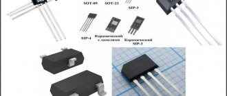
The photo below shows what the sensor looks like and where it is installed in some cars.
In the distributor
Crankshaft sensor
Camshaft sensor
Tachometer sensor
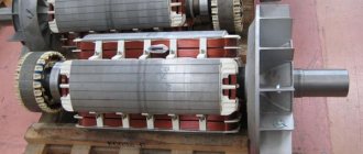
Hall sensor in the electric motor
DIY repair and replacement
If structural elements are damaged, the sensor cannot be repaired. The car owner needs to exchange the part for the original sensor or find an analogue in reference books or catalogs. The algorithm for installing a new sensor depends on the design features of the car. To perform the work, you need a set of plumbing tools (wrenches and screwdrivers). The procedure takes 10–20 minutes.
To replace a faulty camshaft position sensor, you must (using the example of a Lada Priora with a 16-valve engine):
- Find the sensor installation point using the electrical diagram or wiring harness connected to the front engine cover near the crankshaft pulley.
- Remove the wiring block and unscrew the 2 bolts, and then carefully remove the sensor from the mounting socket.
- Inspect the product. If there are traces of mechanical impact on the body, remove the plastic casing and check the condition of the gas distribution mechanism. Otherwise, install a new sensor, tighten the mounting bolts and connect the signal cable. When installing, make sure there is a rubber seal.
A number of car manufacturers recommend replacing the Hall sensor after 100–150 thousand kilometers.
Such requirements are determined by harsh operating conditions (units operate under conditions of temperature changes and are subject to vibration loads). Heating and cooling cycles negatively affect semiconductors and can destroy the plastic case. Water or condensation penetrates into cracks and accelerates sensor failure.
To replace the sensor, you need to find the sensor installation point.
To replace the sensor in the distributor:
- Unfasten the latches and remove the cover.
- Place marks on the crankshaft pulley and timing gear.
- Unscrew the mounting bolts and remove the ignition distributor for further disassembly.
- Remove the faulty sensor and inspect and service the structural elements.
- Install the new sensor and reassemble in reverse order.
- Check engine performance and adjust the ignition (if necessary).
Device
The device of a simple hall sensor consists of:
- Permanent magnet. It creates a magnetic field that acts on the semiconductor, in which a low voltage current is created;
- Magnetic cores. This element perceives the action of the magnetic field and generates current;
- Rotating rotor. This is a curved metal plate that has slots. When the shaft of the main device rotates, the rotor blades alternately block the influence of the magnet on the rod, which creates impulses inside it;
- Plastic housings.
A budget option for switching to a contactless system
The contacts of the mechanical breaker “burn out” and wear out, so they have to be periodically cleaned and the gap adjusted. Installing the Sonar IR module (costing 700÷900 rubles) in the distributor allows owners of classic VAZs (2101-2107) to be spared from this routine work.
The device consists of:
- optical sensor (infrared radiation source and photodetector);
- electrical signal amplifier;
- switching transistor.
Important! All of the above is mounted in a miniature waterproof housing, which makes it quite easy to install it in place of a standard contact breaker.
The operating principle of the module is as follows:
- When the distributor rotor rotates, its cams periodically block the light flux of the optical sensor.
- Electrical impulses from the photodetector are amplified by a built-in microcircuit and supplied to a control transistor, which opens/closes the circuit of the primary winding of the coil.
On a note! LED indicators (red and green) inform about the state of the electronic switching key (closed/open).
Types and scope of application
All Hall sensors are divided into two categories. The first category is digital, and the second is analog. These devices are successfully used in various industries, including the automotive industry. The simplest example of this sensor is DPKV (measures the position of the crankshaft as it rotates).
Analog Hall Sensor Element
In other industries, similar devices are used, for example, in washing machines (weighing laundry based on the rotation speed of a full drum). Another common application of such devices is in a computer keyboard (small magnets are located on the back of the keys, and the sensor itself is installed under an elastic polymer material).
Professional electricians, when measuring the current strength in a cable without contact, use a special device that also contains a Hall sensor, which reacts to the strength of the magnetic field created by the wires and produces a value corresponding to the strength of the magnetic vortex.
In the automotive industry, Hall sensors are implemented in various systems. For example, in electric cars, these devices monitor the battery charge. Crankshaft position, throttle valve, wheel speed, etc. - all this and many other parameters are determined by Hall sensors.
Useful tips
- Since most often the cause of malfunctions lies in the condition of the wires, you should not skimp on them. High-quality wires that have silicone insulation are durable and reliable.
- Incorrect fastening of the wire block is often the reason why the switch breaks. After installing the part, it is necessary to check the condition of the connector.
- If, after installing a contactless ignition system, the tachometer no longer performs its functions, then it is necessary to additionally install a capacitor in the circuit between it and the coil.
Linear (analog) Hall sensors
In such sensors, the voltage depends linearly on the strength of the magnetic field. In other words, the closer the sensor is to the magnetic field, the higher the output voltage. These types of devices do not have a Schmidt trigger or a switching output transistor. The voltage in them is taken directly from the operational amplifier.
The output voltage of analog Hall sensors can be generated by either a permanent magnet or an electric magnet. It also depends on the thickness of the plates and the current that flows through this plate.
Logic dictates that the sensor's output voltage can be increased indefinitely as the magnetic field increases. Actually this is not true. The output voltage from the sensor will be limited by the supply voltage. The peak output voltage at the sensor is called the saturation voltage. Once this peak is reached, there is no point in continuing to increase the magnetic flux density.
For example, current clamps work on this principle, with the help of which the voltage in a conductor is measured without contact with the wire itself. Linear Hall sensors are also used in instruments that measure magnetic field density. Such devices are safe to use, since they do not require direct contact with a conductive element.
Example of using an analog element
The figure below shows a simple circuit of a sensor that measures current and operates on the Hall effect principle.
A – conductor; B – open magnetic ring; C – analog Hall sensor; D – signal amplifier
This current sensor works very simply. When current flows through a conductor, a magnetic field is created around it. The sensor records the polarity of this field and its density. Next, a voltage corresponding to this value is generated in the sensor, which is supplied to the amplifier and then to the indicator.
How large electrical loads can be controlled using Hall sensors
We already know that the output power of the Hall sensor is very small (10 to 20 mA). Therefore, it cannot directly control large electrical loads. However, we can control large electrical loads using Hall effect sensors by adding an open collector NPN transistor (current drain) to the output.
The NPN (current sink) transistor functions in the saturated state as a sink switch. It closes the output contact to ground when the flux density exceeds the preset ON value.
The output switching transistor can be in different configurations such as open emitter transistor, open collector transistor, or both. This is how it provides a push-pull output that allows it to draw enough current to drive large loads directly.
Digital Hall sensors
Analog devices operate based on the strength of the magnetic field. The higher it is, the greater the voltage in the sensor. Since the introduction of electronics into various control devices, the hall sensor has acquired logical elements.
Digital Hall Sensor Element
The device either detects the presence of a magnetic field or does not detect it. In the first case, this will be a logical unit, and a signal is sent to the actuator or control unit. In the second case (even with a large magnetic field that has not reached the limit threshold), the device does not record anything, which is called a logical zero.
In turn, digital devices are of unipolar and bipolar types. Let's briefly look at what their differences are.
Unipolar
As for unipolar options, they are triggered when a magnetic field of only one polarity appears. If you bring a magnet with the opposite polarity to the sensor, the device will not respond at all. The device deactivates when the magnetic field strength decreases or disappears altogether.
The required unit of measurement is issued by the device at the moment when the magnetic field strength is maximum. Until this threshold is reached, the device will show the value 0. If the magnetic field induction is small, the device is not able to detect it, and therefore shows a zero value. Another factor that affects the accuracy of measurements by the device is its distance from the magnetic field.
Bipolar
In the case of bipolar modification, the device is activated when an electromagnet creates a specific pole, and deactivated when exposed to the opposite pole. If the magnet is removed while the sensor is on, the device will not turn off.
Analog and digital solutions
Sensors based on the Hall effect record potential differences. The analog solution discussed above is based on converting field induction into voltage, taking into account polarity and field strength.
The principle of operation of a digital sensor is to detect the presence or absence of a field. If the induction reaches a certain value, the sensor notes the presence of a field. If the induction does not correspond to the required indicator, then the digital sensor indicates the absence of a field. The sensitivity of the sensor is determined by its ability to detect a field at a particular induction.
A digital Hall sensor can be bipolar or unipolar. In the first case, the device is activated and turned off by changing the polarity. In the second case, switching occurs when a field appears, the sensor is turned off as a result of the fact that the induction decreases.
Based on operation
Based on the operation, Hall effect sensors can be divided into two types:
- bipolar;
- unipolar.
Bipolar Hall sensor
As the name suggests, these sensors require both positive and negative magnetic fields to operate. The positive magnetic field of the magnet's south pole is used to activate the sensor, and the negative magnetic field of the north pole is used to turn it off.
Unipolar Hall sensor
As the name suggests, these sensors only require the positive magnetic field of the magnet's south pole to be activated. The same polarity is used to turn off the sensor.
Purpose of DC in the car ignition system
Hall sensors are used in contactless ignition systems. In them, this element is installed instead of a breaker slider, which turns off the primary winding of the ignition coil. The figure below shows an example of a Hall sensor, which is used in cars of the VAZ family.
A – Hall sensor; B – permanent magnet; With a plate blocking the free influence of the magnet
In more modern ignition systems, the Hall sensor is used only to determine the position of the crankshaft. This sensor is called a crankshaft position sensor. The principle of its operation is identical to the classic Hall sensor.
Only the electronic control unit, which is programmed to suit the characteristics of the engine, is responsible for interrupting the primary winding and distributing the high-voltage pulse. The ECU is capable of adapting to different operating modes of the power unit, changing the ignition timing (in old-style contact and non-contact systems, this function is assigned to the vacuum regulator).
How to check households if suspicions arise
This device is very reliable, but there is no absolute protection against malfunction. Therefore, sometimes you have to check these sensors too.
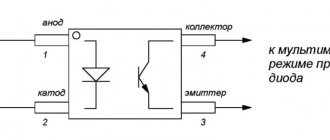
- The simplest thing is to replace the DH with a known good one. This will save you from fiddling with probes, probes and oscilloscopes. And the sensor is inexpensive, it is always useful to have it in stock, if not for replacement, then precisely for checking a faulty injection or ignition system.
- People who know the principle of operation of the Hall sensor can check it with the simplest and not so simple instruments. For example, a probe probe with an LED. The sensor output is an open collector cascade. This means that in the physical zero position the transistor is open, and if the probe is connected between the power supply plus and the DC output, the indicator will light up. By moving the reference point in front of the poles of the sensor, you can make it blink, which will almost certainly indicate the serviceability of the DC and connected wiring circuits.
- The word “almost” was used in the sense that you can accurately verify that it is working only with the help of a digital storage oscilloscope, which many diagnosticians have as an attachment to their laptop. Using it, you can check a parameter that is inaccessible to probes - the speed of the sensor. The voltage fronts should be quite steep, which is what the oscilloscope will show. A “flooded” front may be the very case when the sensor seems to be working, and a probe or multimeter confirms this, but the system fails and errors appear.
Almost all the cases explaining what a Hall sensor is in a car have been considered, it remains to mention the very possible less obvious presence of these small devices in car electronics. Many machines are equipped with fairly powerful electric motors, where Hall sensors are also used to operate the power electronics, monitoring the position of the rotor in the magnetic field. And even this, perhaps, the penetration of DH into the car does not end. A compact, reliable and accurate device will always find a place of work in a modern car that is increasingly becoming equipped with electronics.
Ignition with Hall sensor
In old-style contactless ignition systems (the on-board system of such a vehicle is not equipped with an electronic control unit), the sensor operates in the following sequence:
- The distributor shaft rotates (connected to the camshaft).
- A plate fixed to the shaft is located between the Hall sensor and the magnet.
- There are slots in the plate.
- When the plate rotates and free space is formed between the magnet, a voltage is generated in the sensor due to the influence of the magnetic field.
- The output voltage is supplied to a switch, which switches between the windings of the ignition coil.
- After the primary winding is turned off, a high-voltage pulse is generated in the secondary winding, which enters the distributor (distributor) and goes to a specific spark plug.
Despite the simple operation scheme, the contactless ignition system must be perfectly tuned so that a spark appears in each spark plug at the right moment. Otherwise, the engine will work unstably or won’t start at all.
Possible breakdowns and malfunctions
The main signs of a breakdown of the electronic Hall sensor:
- A sudden increase in fuel consumption , accompanied by difficult starting or a drop in acceleration dynamics. The cause is a breakdown or contamination of the sensor, causing the injectors to operate incorrectly. Excess gasoline is released with the exhaust gas stream into the cavity of the catalytic converter. An increase in temperature due to combustion of the mixture leads to destruction of the ceramic insert and blockage of the exhaust gas channels.
- Switching the automatic transmission into emergency mode with limited speed. When you restart the engine, the problem may disappear for several minutes. The control unit detects an erroneous signal and switches the electronics to emergency operation mode. The symptom is observed on some imported cars.
- Unstable engine operation if the camshaft or crankshaft sensor is damaged, when the tachometer needle may float. This behavior of the engine leads to increased fuel consumption. If the sensor in the ignition system breaks down, the start of the power unit is blocked or the engine stalls when trying to gain speed.
- Turning on the Check Engine indicator while simultaneously recording the error code in the memory of the control units. The information is read using a tester connected to the OBD-II diagnostic connector. Some owners experience the indicator turning off after warming up the engine or increasing the rotation speed of the power unit.
Unstable motor operation is a sign of sensor failure.
Advantages of an automotive Hall sensor
With the introduction of electronic elements, especially in systems that require fine tuning, engineers have been able to make systems more stable compared to their mechanically controlled counterparts. An example of this is the contactless ignition system.
A sensor operating on the Hall effect principle has several important advantages:
- It is compact;
- It can be installed in absolutely any part of the car, and in some cases even directly in the mechanism itself (for example, in a distributor);
- There are no mechanical elements in it, so its contacts do not burn out, as, for example, in a contact ignition system breaker;
- Electronic pulses respond much more effectively to changes in the magnetic field, regardless of the shaft rotation speed;
- In addition to reliability, the device provides a stable electrical signal in different operating modes of the motor.
But this device also has significant disadvantages:
- The biggest enemy of any electromagnetic device is interference. There are plenty of them in any engine;
- Compared to a conventional electromagnetic sensor, this device will be much more expensive;
- Its performance is affected by the type of electrical circuit.
Contactless, what's the trick?
As you probably remember, the problems found in contact ignition systems of cars were associated with mechanical parts.
More precisely, the contact groups of the breaker and distributor often burned out from the current pulses that occurred when voltage was applied to the ignition coil, and in general they were severely subjected to physical wear due to constant friction. These problems were partially solved in the contact-transistor version, but it was still far from ideal.
A new step towards solving problems was the contactless system. In it, the developers decided to completely abandon the contact breaker and replaced it with a new unit - a contactless sensor. Read on to find out exactly what role this device plays.
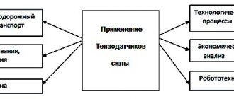
Application of Hall sensors
As we have already said, devices based on the Hall principle are used not only in cars. Here are just a few of the industries where a Hall effect sensor is either possible or mandatory.
Application of linear sensors
Linear type sensors are found in:
- Devices that determine current strength in a non-contact manner;
- Tachometers;
- Sensors that determine the level of vibration;
- Ferromagnetic sensors;
- Sensors that determine the angle of rotation;
- Non-contact potentiometers;
- Brushless motors operating on direct current;
- Working substance flow sensors;
- Detectors that determine the position of working mechanisms.
Application of digital sensors
As for digital models, they are used in:
- Sensors that determine the rotation speed;
- Synchronization devices;
- Sensors of the ignition system in the car;
- Position sensors for elements of working mechanisms;
- Pulse counters;
- Sensors that determine the position of the valves;
- Door locking devices;
- Working substance flow meters;
- Proximity sensors;
- Contactless relays;
- In some printer models, as sensors that detect the presence or position of paper.
Possible faults
If the car does not start, you should first check that the wiring is connected correctly. You can also unscrew the spark plugs and check for a spark.
It is quite possible that the distributor was positioned incorrectly during installation, in particular, the Hall sensor did not align with the center of the technological hole, and as a result, the moment of sparking was disrupted.
To eliminate the malfunction, you should make a new adjustment with preliminary installation of marks on the pulley with marks on the cover, setting the position of the slider, and then install the Hall sensor.
It is also possible that the contactless ignition of the VAZ-2101 does not work because one of the components is simply faulty. Therefore, before installation, it is advisable to check the switch, distributor and coil on a car equipped with such an ignition system.
What malfunctions can there be?
Here is a table of the main malfunctions of the hall sensor and their visual manifestations:
| Malfunction: | How it manifests itself: |
| The sensor operates more often than the crankshaft goes through a full cycle | Fuel consumption increases (while other systems, for example, fuel, work properly) |
| The device fires every once in a while or periodically switches off completely | While the car is moving, the engine may stall, the car jerks, engine power drops, and it is impossible to accelerate the car faster than 60 km/h. |
| Hall sensor malfunction | In some foreign cars of the latest generation, the gear shift lever is blocked |
| The crankshaft position sensor is broken | The engine cannot be started |
| Errors in the electrical system, in which the main element is the hall sensor | The self-diagnosis error light of a specific component, for example, the engine, lights up on the dashboard at idle speed, but disappears when the engine picks up speed. |
It often happens that the sensor itself is working, but it feels like it has failed. Here are the possible reasons for this:
- Dirt on the sensor;
- Broken wire (one or more);
- Moisture has entered the contacts;
- Short circuit (due to moisture or damaged insulation, the signal wire is shorted to ground);
- Damage to cable insulation or shield;
- The sensor is connected incorrectly (the polarity is reversed);
- Problems with high voltage wires;
- Malfunction of the car control unit;
- The distance between the sensor elements and the part being monitored is incorrectly set.
How to check it yourself
It’s a completely standard situation: the engine doesn’t start well, is unstable, or stalls periodically. The described symptoms may well be caused by a malfunction of the Hall sensor installed in the ignition distributor. How to check its functionality? The most correct way (from a technical point of view) is to do this using an oscilloscope. However, such an expensive measuring device is rarely found “in the household” of a car enthusiast. Well, almost everyone has a standard multimeter. It is with its help that you can quite easily check the functionality of the sensor. To do this, we first assemble the circuit:
Then everything is simple:
- We turn on the power supply (or simply connect the wires to the battery removed from the car): the voltmeter readings should be close to zero (usually no more than 0.3÷0.4 V).
- Insert a flat metal object into the sensor slot (a metal file or knife will do). If the device readings increase sharply (the voltage value depends on the brand of the sensor being tested), then the Hall sensor is working. Otherwise, we can conclude that interruptions in the operation of the engine were caused precisely by it, and, therefore, it must be replaced with a new one.
If you do not have a multimeter, then instead you can use an LED (designed for a direct voltage of about 12 V and costing about 10÷12 rubles) to check the sensor using a similar algorithm.
On a note! As a power source, you can use an adjustable laboratory unit or, in extreme cases, a 9 V Krona battery.
Sensor check
To ensure that the sensor is faulty, a test must be performed before replacing it. The easiest way to determine whether the problem is really in the sensor is to run diagnostics on an oscilloscope. The device not only detects malfunctions, but also indicates an imminent breakdown of the device.
Since not every motorist has the opportunity to carry out such a procedure, there are more accessible ways to diagnose the sensor.
Diagnostics with a multimeter
First, the multimeter is set to DC measurement mode (20V switch). The procedure is performed in the following sequence:
- The armored wire is disconnected from the distributor. It is connected to ground so that as a result of diagnostics the car does not accidentally start;
- The ignition is activated (the key is turned all the way, but the engine does not start);
- The connector is removed from the distributor;
- The negative contact of the multimeter is connected to the ground of the car (body);
- The sensor connector has three contacts. The positive contact of the multimeter is connected to each of them separately. The first contact should show a value of 11.37V (or up to 12V), the second - also in the region of 12V, and the third - 0.
Next, the sensor is checked in operation. To do this you need to do the following:
- From the input side of the wires, metal pins (for example, small nails) are inserted into the connector so that they do not touch each other. One is inserted into the central contact, and the other is inserted into the negative wire (usually white);
- The connector fits onto the sensor;
- The ignition is turned on (but we do not start the engine);
- We fix the negative contact of the tester to the negative (white wire), and the positive contact to the central pin. The working sensor will give a reading of approximately 11.2V;
- Now the assistant must turn the crankshaft several times with the starter. The multimeter reading will fluctuate. You need to note the minimum and maximum values. The lower bar should not exceed 0.4V, and the upper bar should not fall below 9V. In this case, the sensor can be considered serviceable.
Resistance check
To measure resistance you will need a resistor (1 kOhm), a diode light bulb and wires. A resistor is soldered to the light bulb leg, and a wire is connected to it. The second wire is fixed on the second leg of the light bulb.
The check is carried out in the following sequence:
- Remove the distributor cover, disconnect the block and contacts of the distributor itself;
- The tester is connected to terminals 1 and 3. After activating the ignition, a value within 10-12 volts should appear on the display;
- Using the same circuit, a light bulb with a resistor is connected to the distributor. If the polarity is correct, the control will light up;
- After this, the wire from the third terminal is connected to the second. Then the assistant turns the engine using the starter;
- A blinking light indicates a working sensor. Otherwise, it must be replaced.
Creating a Hall Controller Simulation
This method allows you to diagnose the hall sensor in the absence of a spark. The contact strip is disconnected from the distributor. The ignition is activated. The output contacts of the sensor are connected to each other using a small wire. This is a kind of simulator of the hall sensor that created the impulse. If a spark forms on the central cable, it means that the sensor has failed and needs to be replaced.
Structure and functions of BSZ
Based on the figure, the operating principle of the system is briefly explained:
Drawing. Components of a transistor ignition system
- Accumulator battery
- Ignition and starter switch
- Ignition coil
- Switch
- Ignition sensor
- Sensor-distributor
- Spark plug
When the ignition (2) is turned on, supply voltage is supplied to the primary winding of the ignition coil (3). Current flows through the primary winding; as soon as the commutator (4) receives a signal from the ignition sensor (5), the current in the primary winding is interrupted. Terminal 1 of the ignition coil is connected to ground via a switch. A high voltage of more than 20 kV is induced in the secondary winding.
The secondary voltage of the ignition system is transmitted through terminal 4 of the ignition coil to the distributor sensor to the corresponding cylinder and spark plug.
The control unit determines the crankshaft rotation speed (sensor signals) and, based on it, controls the accumulation time of the current of the primary winding of the ignition coil (the duration of the open state of the output transistor or thyristor of the ignition system) and its magnitude. In accordance with the speed and voltage of the battery, shortly before the appearance of the ignition spark, the set value of the primary current is set, that is, as the speed increases, the duration of the current flow increases in the same way as when the battery voltage decreases.
When the ignition is turned on and the engine is not running (no sensor signal), after a while (usually after one second), the current in the primary winding of the ignition coil is turned off. As soon as the control unit receives a sensor signal (for example, during startup), it returns to operating status.
To adapt the ignition timing to different load conditions, adjustment is carried out in the same way as in contact ignition systems, mechanically through a membrane mechanism of a vacuum regulator, as well as a centrifugal regulator. As a result, the sensor signal (and with it the ignition timing) changes depending on the engine speed and load.
Drawing. Interaction diagram of vacuum and centrifugal adjustment when controlling the ignition using an inductive sensor
- Centrifugal regulator
- Vacuum ignition timing regulator with membrane mechanism
- Ignition distributor shaft 4 - Hollow shaft
- Ignition distributor inductive sensor stator
- Control pulse sensor rotor
- Ignition distributor rotor
Inductive signal formation in a contactless transistor ignition system by storing energy in inductance
As a result of rotation of the rotor of the control pulse sensor, the magnetic field changes and an alternating voltage shown in Figure a, b is created in the induction winding (stator). In this case, the voltage increases as the rotor teeth approach the stator teeth. The positive half-cycle of the voltage reaches its maximum value when the distance between the stator and rotor teeth is minimal. As the distance increases, the magnetic flux sharply changes its direction and the voltage becomes negative.
Drawing. Control pulse sensor based on the induction principle a) Process diagram
- Permanent magnet
- Core induction winding
- Variable air gap
- Control pulse sensor rotor
b) time characteristic of alternating voltage induced by the control pulse sensor tz = ignition timing
At this point in time (tz), as a result of interruption of the primary current by the commutator, the ignition process is initiated.
Recommended: What is car engine torque?
The number of rotor and stator teeth in most cases corresponds to the number of cylinders. In this case, the rotor rotates at a reduced crankshaft speed. Peak voltage (± U) at low speed is approx. 0.5 V, at high - approx. up to 100 V.
The ignition timing can only be monitored when the engine is running, since without rotation of the rotor the magnetic field does not change and, as a result, no signal is created.
Trouble-shooting
If you want to repair the hall sensor yourself, you will first need to purchase a so-called logical component. You can select it according to the model and type of sensor.
The repair itself is carried out as follows:
- Using a drill, a hole is made in the center of the body;
- The wires of the old component are cut with a utility knife, after which grooves are laid for new wires that will be connected to the circuit;
- The new component is inserted into the housing and connected to the old contacts. You can check the correct connection using a test diode light with a resistor on one contact. Without the influence of the magnet, the light bulb should go out. If this does not happen, then you need to change the polarity;
- New contacts must be soldered to the device block;
- To ensure that the work was carried out correctly, the new sensor should be diagnosed using the above methods;
- Finally, the housing must be hermetically sealed. To do this, it is better to use heat-resistant glue, since the device is often exposed to high temperatures;
- The controller is assembled in the reverse order.
Troubleshooting
If damage to the housing is detected that affects the performance of the sensor, or the microcircuit fails, a new product should be installed.
... about sensor repair
It is not recommended to restore an old sensor with glue or electrical tape.
The car owner needs to select a spare element (for example, from a catalog) and carry out the repairs himself or at a service center.
If damage is detected, a new product is installed.
How to replace the sensor yourself?
Not every car enthusiast has time to manually repair sensors. It’s easier for them to buy a new one and install it instead of the old one. This procedure is carried out as follows:
- First of all, you need to remove the terminals from the battery;
- The distributor is removed, the block with wires is disconnected;
- The distributor cover is removed;
- Before completely dismantling the device, it is important to remember how the distributor itself was located. It is necessary to align the timing marks and crankshaft marks;
- The distributor shaft is removed;
- The hall sensor itself is disconnected;
- A new one is installed in place of the old sensor;
- The block is assembled in the reverse order.
The latest generation of sensors have a long working life, so frequent replacement of the device is not required. When servicing the ignition system, you must also pay attention to this tracking device.
A little history
Wiring diagram for the hall sensor on a VAZ
In 1879, a Western scientist at the Baltimore University, E. Hall, discovered a sensational and previously unnoticed effect - if within the radius of the zone of influence of an electromagnet a crystalline material with semiconductor properties (any rectangular plate) is placed, and to its small voltage is applied to the sides, then a current will appear on the wide sides of the semiconductor.
The current value can reach a couple of hundred mV.
Interestingly, this sensational discovery was delayed in technical application for seventy-five years, which was due to the difficulties of factory production of plates of this type.
Hall sensor connector block
Later, with progress in the field of study and production of electronic components, it was possible to produce a small device containing everything needed. In other words, the chip, the magnet, and everything else.
Kinds
There are two types of Hall sensors:
- Digital sensors. They work to determine the magnetic field. If the induction reaches a certain limit, the sensor gives a signal about the presence of a magnetic field. If the limit is not reached, then the signal is zero. Weak induction and low sensitivity of the sensor do not give a signal of the presence of a field. The disadvantage of this type of sensor is that it has a threshold dead zone. Digital Hall sensors are divided into unipolar and bipolar:
- Unipolar Hall sensors operate if there is a field of any polarity, turning off when the induction decreases. — Bipolar Hall sensors are triggered by a change in field polarity. With one polarity, the sensor is turned on, and with the other, it is turned off.
- The analog type of Hall sensors changes the field induction into a potential difference. The value of the sensor depends on the polarity and its strength. It is necessary to take into account the distance at which the sensor is located.
Application
Hall sensors are included in many devices. They are most often used in measuring magnetic induction field strength, in electric motors, and in ion rocket engines. Hall sensors are widely used in the ignition systems of modern cars.
They are also used in proximity switches, reed switches, when measuring current, liquid level and other places. Their main advantage is the impact without physical contact.
Digital Hall sensor.
How to check the health of the Hall sensor on a car
In everyday life, motorists most often encounter this problem. The simplest way is to simply replace it with a working sensor. If the ignition system works after replacement, then the sensor needs to be replaced. If there is nothing to replace the sensor being tested, then a simple device is assembled that can simulate the operation of a Hall sensor. Take a piece of wire and a triple connector from the ignition distributor. These items work similar to a sensor.
To control, use a conventional multimeter. If the sensor fails, the tester will show 0.4 volts or less. The operation of the sensor is also checked by checking the spark when the ignition is connected. Before this, connect the ends of the wire to the outputs of the switch. If the malfunction does not occur on the car, but on other equipment, then a tester is needed. The test method will depend on the device in which the sensor is installed.
Hall sensors in smartphones
Mobile gadgets have many functional blocks. Among them there are auxiliary sensors, one of which is a Hall sensor. In modern communication devices, such sensors are measuring elements that are used to determine the power of the magnetic field and its changes. They are named after the scientist Hall.
Why is a Hall sensor installed in a smartphone?
This touch element has many possibilities. One of them is the measurement of magnetic induction of devices, as well as contactless control. Expensive smartphone models have a magnetometer, the operation of which is based on a Hall sensor.
It will be interesting➡ Diode bridge - what is it?
On many mobile phones this sensor is not fully implemented. This sensor is mainly used for the following tasks:
- Digital compass. Used for navigation programs and increasing positioning speed.
- Optimizing the interaction of the device with various accessories, magnetic cases.
- Using a sensor in folding phone models to turn the screen on and off when the cover moves.
An example of how a magnetic Hall sensor in a case and a smartphone works is that when the case is opened and closed, the screen is automatically locked. The sensor responds to the movement of the magnet and to the strengthening of the magnetic field.
Hall sensor in a smartphone.
Features of using a Hall sensor in a car
In a car, a Hall sensor operates on the principle of a conventional key - a contactor and a circuit breaker. At the same time, the magnet rotates in the distributor and affects the sensor itself, which is fixed in a stationary manner. When the latter begins to “feel” the magnetic field, it begins to send impulses, which, in turn, cause a spark to ignite. For a car, the Hall sensor is one of the key elements of its ignition system and is present in any model, regardless of configuration and cost.
Sometimes this device can be used in digital car speedometers or tachometers, and can also be used to check the speed of transmission data and to monitor the operation of the car's anti-lock braking system.
In addition, this unit is highly reliable. It can work for many years, but breaks down, as a rule, due to strong physical impact or due to severe contamination. Very often the sensor is installed so that it can be easily removed and replaced at any time. The only exceptions are those devices that are used to monitor the most complex automotive systems.
Application of Hall sensor in a car
Operating principle
You will need a plate and a DC battery. We connect the plate to the battery. Electric current begins to flow from plus to minus, caused by the movement of charged particles. From the physics course, these particles, or in other words, electrons fly against the flow of current. Now let’s bring two magnets to the plate with different poles so that the induction lines pass through its cross section.
The so-called Lorentz force arises, which deflects electrons flying along the plate to the side. Because of this, a potential difference arises at the edges of the plate. This potential difference, in other words, voltage, will vary depending on the current and magnetic field. This effect is named after the man who discovered it in 1879. It was Edwin Hall.
Interesting on the topic: How to check a zener diode.
Based on this effect, a large number of sensors are produced that make it possible to measure both direct and alternating current in it without physically breaking the wire, since when current flows in the conductor, an electromagnetic field is created. It, like those magnets brought to the plate, changes the output voltage of the Hall sensor. But the problem arises that this field, when not very large currents flow, is itself very small. In order to increase it, we will use a ferrite ring, which has special magnetic properties and will allow us to increase the electromagnetic field we need to a level to detect the flow of current in the conductor.
The Hall sensor is homemade.
Assembly of a current sensor based on the Hall effect
Let's try to make our own current sensor. You will need a ferrite ring and a Hall sensor. Finding a ferrite ring is not much of a problem. They are found in computer power supplies or energy-saving lamps, and are also sold in radio stores at prices ranging from 10 to 100 rubles, depending on the size of the ring itself. In our case, there is a ring with a diameter of 28 mm for 55 rubles.
Rings of various diameters up to 10 mm are suitable. The larger the ring, the more sensitive the current sensor will be. As for the Hall sensor, it can be ordered from a well-known website. It's inexpensive. Or it can be found in non-working fans, laptops and other devices where it can be used. Hall sensors Analog and digital (Discrete).
What is a Hall sensor.
Discrete ones operate on the principle of transistors, that is, when a certain magnetic field level is exceeded, the sensor is triggered. The analog type changes its output voltage depending on the magnitude of the magnetic field passing through it. We will need an analog Hall sensor. If you want to not only detect the flow of current through a conductor, but also know the approximate value of this current.
It will be interesting➡ Designation of chokes on the diagram
Electronic ignition, with electronic unit UOZ for burki..
Alexander 78
Active participant
They asked me to duplicate the topic from a parallel forum, I will do it with pleasure.
The topic is not new for 2T technology, but few people have used it on the burka. I didn’t immediately like the original ignition. every little detail affects the characteristics of the spark.
I didn’t consider installing the distributor - the mechanics + the distributor is designed for speeds up to 3000, turn up to 6000.
I settled on electronic ignition with a VAZ 2108 switch with a hall sensor (or optical sensor) and a Saruman ignition timing driver.
Basic elements of 2-circuit ignition
Crankshaft position sensor, testing methods, symptoms of malfunction, location
This ignition option consists, like the usual SZ of the new model, of a switch, a coil and a distributor. Of course, spark plugs, various fasteners and chips, and good wiring corresponding to the new ignition are required.
Before you begin assembling the dual-circuit ignition, you will need to change something in the distributor. We are talking about the DH curtain, which should now be installed with 2 slots (the standard version of the curtain is 4 slots). In other words, the curtain will have only 2 positions: the beginning of the shielding and the end of the shielding.
Curtain 2-circuit ignition (left) and conventional
This type of curtain is also called 90x90.
You can use a regular, classic distributor in 2-circuit ignition. Zhigulevsky, Volkswagen, etc.
As for the number of DCs in the distributor. It is more common to see 2-circuit ignition with two DCs. However, no less popular is the dual-circuit ignition scheme with one sensor. It, in turn, can also be implemented in 2 ways: if the distributor has 2 HHs installed, but only one is working, or if initially there is 1 HH.
The coil can also be used as a regular one, without any complex circuit. As a rule, 2 coils are also installed.
Here's what a dual-circuit ignition circuit with 1 DC usually looks like on cars:
- 1 DC or distributor with one working sensor;
- naturally, distribute one;
- two ignition coils placed side by side;
- 1 two-channel Astra switch or 2 regular ones (sometimes Astra and plus 1 simple one for emergency power supply of households).