What is an operational amplifier
An op-amp is an integrated circuit (IC), the main purpose of which is to amplify the value of direct current. It has only one output, which is called differential. This output has a high signal amplification factor (Kу). Op-amps are mainly used when constructing circuits with negative feedback (NFB), which, with the main gain characteristics, determines the K of the original circuit. Op-amps are used not only in the form of individual ICs, but also in various blocks of complex devices.
The op-amp has 2 inputs and 1 output, and also has pins for connecting a power source (PS). The operating principle of an operational amplifier is simple. There are 2 rules taken as a basis. The rules describe simple IC operation processes that occur in an op-amp, and how the IC works is clear even to dummies. At the output, the voltage difference (U) is 0, and the op-amp inputs consume almost no current (I). One input is called non-inverting (V+) and the other is inverting (V-). In addition, the op-amp inputs have high resistance (R) and consume virtually no I.
The chip compares the U values at the inputs and produces a signal, pre-amplifying it. Ku op-amp has a high value, reaching 1,000,000. If a low U is supplied to the input, then at the output it is possible to obtain a value equal to U of the power source (Uip). If U at the V+ input is greater than at V-, then the output will have a maximum positive value. When the inverting input is powered with positive U, the output will have a maximum negative voltage.
The main requirement for op-amp operation is the use of a bipolar power supply. It is possible to use a unipolar power supply, but the capabilities of the op amp are greatly limited. If you use a battery and take its positive side as 0, then when measuring the values you will get 1.5 V. If you take 2 batteries and connect them in series, then U will add up, i.e. the device will show 3 V.
Non-inverting amplifier circuit
In the circuit of a non-inverting amplifier, the situation is very similar to that of an inverting amplifier, the only difference being that the signal does not invert, that is, the phase is preserved. The graph below shows what happens to the amplified signal:
Just as in the previous circuit, the gain is k=2, and a sinusoidal signal is applied to the input. As you can see, only the signal amplitude has changed.
Below is a circuit diagram of using an op amp as a non-inverting amplifier:
This amplifier circuit is also very simple; there are two resistors. The input signal is applied to the positive input of the op-amp. To calculate the gain you need to apply the formula:
From the formula it is clear that the gain cannot be less than unity, i.e. such a circuit does not allow suppressing the signal.
Types and symbols on the diagram
With the development of electrical circuitry, operational amplifiers are constantly being improved and new models appear.
Classification by areas of application:
- Industrial ones are a cheap option.
- Precision (precise measuring equipment).
- Electrometric (low value of Iin).
- Micropower (low power consumption).
- Programmable (currents are set using external I).
- Powerful or high-current (giving a higher I value to the consumer).
- Low voltage (operate at U<3 V).
- High voltage (designed for high U values).
- Fast (high slew rate and amplification frequency).
- Low noise.
- Sound type (low harmonic distortion).
- For bipolar and unipolar type of electrical supply.
- Difference (capable of measuring low U with high noise). Used in shunts.
- Ready-made amplification stages.
- Specialized.
Based on input signals, op-amps are divided into 2 types:
- With 2 entrances.
- With 3 inputs. Input 3 is used to expand functionality. Has internal OOS.
The operational amplifier circuit is quite complex, and there is no point in manufacturing it, and the radio amateur only needs to know the correct circuit for connecting the operational amplifier, but for this he must understand the decoding of its pins.
Basic designations of IC pins:
- V+ is a non-inverting input.
- V- - inverting input.
- Vout - output. Vs+ (Vdd, Vcc, Vcc+) - positive terminal of the IP.
- Vs- (Vss, Vee, Vcc-) - minus IP.
Almost any op-amp has 5 pins. However, some varieties may lack V-. There are models that have additional pins that expand the capabilities of the op-amp.
It is not necessary to mark the power pins, because this increases the readability of the diagram. The power output from the positive terminal or pole of the power supply is located at the top of the circuit.
Offset voltage
Another practical issue for op amp performance is voltage offset. That is, the effect of having an output voltage of a value other than zero when the two input pins are shorted together. Remember that op amps are primarily differential amplifiers: they are supposed to amplify the voltage difference between two input pins and nothing more. When the input voltage difference is exactly zero, we (ideally) expect the output to be exactly zero voltage. However, in the real world this rarely happens. Even if the op amp in question has zero common mode gain (infinite CMRR), the output voltage may not be zero when both inputs are shorted together. This deviation is called the op amp's output level offset.
Op amp output voltage offset
An ideal op-amp outputs exactly zero volts when both inputs are shorted together and connected to ground. However, most standard op amps will bias their output voltage towards a saturation level, either negative or positive. In the example above, the output voltage saturates at a positive 14.7 volts, slightly less than +V (+15 volts) due to the positive saturation limit of that particular op amp. Since the offset drives the output voltage to the point of full saturation, there is no way to tell how much voltage offset is present at the output. If the separate +V/-V power supply was high enough voltage, who knows, maybe the output voltage would be several hundred volts due to the effects of offset!
For this reason, offset voltage is usually expressed in terms of the equivalent magnitude of the differential input voltage producing this effect. In other words, we assume that the op amp is ideal (no bias at all), and a small voltage is applied in series with one of the inputs to force the output voltage one way or the other away from zero. Because the differential gains of op amps are so large, the "input offset voltage" value doesn't necessarily need to account for what we see with shorted inputs:
Input offset voltage
Offset voltage will introduce small errors in any op-amp circuit. So how do we compensate for it? In contrast to common-mode gain, manufacturers typically include means to eliminate offset in packaged op-amps. Typically, two additional pins on the op-amp case are reserved for connecting an external “trimming” potentiometer. These pins are designated as zero offset and are used in the following general manner:
Op amp zero bias circuit
On single op amps such as the 741 and 3130, the zero offset pins are pins 1 and 5 on the 8-pin DIP package. Other op amp models may use different zero offset pins and/or require slightly different trim pot connections. Some op amps do not provide zero offset pins at all! For details, see technical descriptions from manufacturers.
Main characteristics
Op-amps, like other radio components, have TX, which can be divided into types:
- Amplifiers.
- Input.
- Weekend.
- Energy.
- Drifting.
- Frequency.
- Performance.
Gain is the main characteristic of an op-amp. It is characterized by the ratio of the output signal to the input signal. It is also called amplitude or transfer TX, which is presented in the form of dependence graphs. The input values include all quantities for the op-amp input: Rin, bias currents (Icm) and shift (Iin), drift and maximum input differential U (Udiffmax). Icm is used to operate the op-amp at the inputs. Iin is needed for the operation of the input stage of the op-amp. Iin shift - difference Icm for 2 input semiconductors of the op-amp.
When constructing circuits, you need to take these I into account when connecting resistors. If Iin is not taken into account, this can lead to the creation of a differential U, which will lead to incorrect operation of the op-amp. Udiffmax - U, which is supplied between the inputs of the op-amp. Its value characterizes the elimination of damage to the semiconductors of the differential stage.
For reliable protection, 2 diodes and zener diodes are connected back-to-back between the inputs of the op-amp. Differential input R is characterized by the R between two inputs, and common-mode input R is the value between the 2 op-amp inputs that are combined and ground (ground). The output parameters of the op amp include output R (Rout), maximum output U and I. The Rout parameter should be smaller in value to provide better gain characteristics.
To achieve a small Rout, you need to use an emitter follower. Iout changes with the help of collector I. Energy TX is estimated by the maximum power that the op-amp consumes. The reason for the incorrect operation of the op-amp is the spread in the characteristics of the semiconductors of the differential amplifier stage, which depends on temperature indicators (temperature drift). The frequency parameters of the op-amp are basic. They help to amplify harmonic and pulse signals (speed).
The op-amp IC of general and special types includes a capacitor that prevents the generation of high-frequency signals. At frequencies with low values, the circuits have a large coefficient Ku without feedback (OS). With OS, non-inverting switching is used. In addition, in some cases, for example, in the manufacture of an inverting amplifier, the OS is not used. In addition, the op-amp has dynamic characteristics:
- Slew rate of Uout (CH Uout).
- Settling time for Uout (op-amp response when U jumps).
Op-amp - operational amplifier
An operational amplifier (op-amp) is a universal functional element used in modern circuits for generating and converting signals for various purposes in analog and digital technology. Why an operational amplifier? Because such amplifiers are mainly used to perform the operations of summing, differentiating, integrating and inverting signals. Op amps were designed as advanced balanced amplification circuits. Modern op-amps include tens and sometimes thousands of elements: resistors, diodes, transistors, capacitors. The op amp was originally designed to perform mathematical operations in analog computers. The first tube op-amp was created in 1942, and the first integrated op-amp, mA702, was developed in 1963 in America. Now the OU nomenclature includes thousands of items. Since they are all cheap, this contributes to their mass distribution. Signal conversion by an op-amp circuit is determined by the properties of feedback circuits and is highly stable and reproducible. Thanks to the almost ideal characteristics of modern op-amps, the implementation of various electronic circuits based on them turns out to be much simpler than on discrete elements. In order for the op-amp to work with both positive and negative input signals, a bipolar power supply is used. To do this, take two DC sources, which are connected to the corresponding external pins of the op-amp. The principle of negative feedback is that part of the output voltage is returned through the feedback circuit to the input of the amplifier. And if the feedback voltage (FEV) is subtracted from the input voltage, such feedback is called negative feedback (NFV).Let's look at a practical op-amp amplifier circuit. Let's say the input voltage has changed from zero to some positive value Uin. At the first moment, the output voltage Uout, and therefore the feedback voltage Uout, are also zero. In this case, the voltage applied to the input of the operational amplifier will be Ud = Uin. Since this voltage is amplified by an amplifier with a large gain KU, the value of Uout will quickly increase to some positive value and along with it the value of Uout will also increase. This will lead to a decrease in the voltage Ud applied to the amplifier input. The fact that the output voltage affects the input voltage, and in such a way that this influence is directed in the direction opposite to changes in the input value, is a manifestation of negative feedback. After reaching a stable state, the output voltage of the op-amp will be equal to: Uout =KUUd =KU(Uin - Uout). Having solved this equation for Uout, we get: K=Uout /Uin =KU/(1 + KU) Thus, the gain of the op-amp with feedback is determined solely by the feedback and is almost independent of the parameters of the amplifier microcircuit itself. In the simplest case, the feedback circuit is a conventional voltage divider across resistors. The op-amp operates as a linear amplifier, the gain of which is determined only by the attenuation coefficient of the feedback circuit, but if an RC circuit is used as the feedback circuit, then an active filter is formed. The inclusion of diodes and transistors in the OS circuit allows for nonlinear signal conversions.
An ideal operational amplifier should have the following properties:
— infinitely large differential voltage gain KU=Uout /(U1 - U2) (for real op-amps from 1 thousand to 100 million); — zero zero offset voltage Ucm, i.e. when the input voltages are equal, the output voltage is zero (for real op-amps Ucm, reduced to the input, ranges from 5 μV to 50 mV); — zero input currents (for real op-amps from hundredths of pA to units of μA); — zero output resistance (for real low-power op-amps from tens of Ohms to units of kOhms); — instant response to changes in input signals (real op-amps have a time to establish the output voltage from a few nanoseconds to hundreds of microseconds). — high voltage gain, including constant voltage; — low zero offset voltage; — low input currents; — high input and low output impedances; — high coefficient of attenuation of the common-mode component.
Due to the inevitable parasitic capacitances, the op-amp is similar in its frequency properties to a high-order low-pass filter. Systems of this kind, which have a large gain, are prone to instability in the presence of feedback, which manifests itself in the fact that even in the absence of a signal at the input of the system, there are oscillations of a certain amplitude at its output. To ensure the stability of the circuit, its correct installation is important. The conductors connecting the OS resistors to the inverting input of the op-amp must have a minimum length, otherwise a parasitic capacitance will form at the input of the op-amp, which can be 0.5 pF per millimeter of conductor. Together with the OS resistors, it forms an additional link in the feedback loop, which reduces the stability margin.
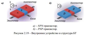
According to the internal circuitry, op-amps are divided into bipolar, bipolar-field and complementary field-effect transistors with an insulated gate. In bipolar field-effect op-amps, field-effect transistors with a pn junction control or MOSFETs are used as inputs in a differential input stage, due to which high input impedance and low input currents are achieved. Most of the op amp range relates to general purpose amplifiers. These are cheap amplifiers of average speed, low accuracy and low output power. You can find out the detailed characteristics and parameters of a particular operational amplifier model by entering its markings in a special form in the upper left part of the site. OU Forum
Op amp material discussion forum - OPERATIONAL AMPLIFIER
SMD FUSES
Provides basic information about planar fuses, including their technical characteristics and applications.
Review of a Chinese device for water electrolysis - photos, videos, description of work.
What are OLED, MiniLED and MicroLED TVs - a brief overview and comparison of technologies.ELECTROMAGNETIC GAUSS RIFLE
Review of several more schemes and ready-made Gauss Gun designs from Aliexpress.
Drifting
Being semiconductor devices, op amps undergo subtle changes in behavior as operating temperature changes. Any change in op amp performance due to temperature is classified as op amp drift. Drift parameters can be specified for bias currents, bias voltages, etc. For more details, see the specific op amp manufacturer's data sheet.
To keep op amp drift to a minimum, we can choose an op amp that has minimal drift, and/or we can do our best to keep the operating temperature as stable as possible. The final step may involve providing some form of thermal management to the internal part of the hardware that houses the op-amp(s). This is not as strange as it might seem at first glance. It is known that, for example, standard laboratory precision voltage reference generators sometimes use "ovens" (thermostats) to maintain sensitive components (such as zener diodes) at a constant temperature. If high accuracy is required with the usual factors of cost and flexibility, this may be an option worth considering.
Summary
Op-amps, being semiconductor devices, are subject to temperature changes. Any change in amplifier performance resulting from changes in temperature is known as drift. Drift is best minimized by controlling the ambient temperature.
Original article:
- Op-Amp Practical Considerations