The power supplies that accompany television antennas with amplifiers are manufactured at a minimum cost and with the same reliability. Since they usually operate around the clock, they often overheat and fail, even at rated AC voltage.
As mentioned above, power supplies for antennas are manufactured at a minimum cost, providing a current consumption of 20 mA at a voltage of 12 volts. However, they maintain good voltage regulation due to the use of a 12-volt stabilizer in the circuit.
A detailed antenna amplifier comparison, including finding the right antenna amplifier for your needs. When choosing the right antenna boosters for your needs, make sure we have never personally reviewed the products, but compared them against product data. All products on the site are intensively researched. Our test reports, test results, and advantages as well as disadvantages are the cumulative result of previous product tests on the Internet. Our team summarizes all the knowledge gained, as well as experience in operation, functions and optics.
What is an antenna amplifier?
All published factual tests are the result of an objective examination of existing data and thus without personal judgment. Amplifier for connecting to the home for cable television. According to the survey, 97 percent TV is people's favorite leisure activity, followed by listening to the radio at 90 percent. This means that TV reception is limited, for example, by picture noise or so-called blocking during digital reception.
Let's look at the antenna amplifier power supply circuit.
Standard antenna amplifier power supply circuit
From the diagram it can be seen that the antenna amplifier power supply consists of: a transformer with built-in fuse T1, a rectifier VD1-VD4, a low-frequency filter C5 and a high-frequency filter C6, a voltage stabilizer DA1, and a 12 V voltage indicator HL1. This circuit is an unregulated power supply for an antenna amplifier.
Even today, many households use satellite dishes to receive a wide variety of television programs. However, certain regions may experience disruptions such as bad weather conditions such as heavy snow, heavy rain or storms.
And in order to counteract these bad weather conditions or strengthen the signal that is received at home, an antenna booster is used. An antenna amplifier is an amplifier that still amplifies the high frequency signal received from the antenna to a low noise level so that the output signal is stronger than what was originally received. Antenna amplifiers are also called broadband RF amplifiers when used to increase signal strength.
It is possible to adjust the signal level using an adjustable power supply for the antenna amplifier. The circuit is almost similar to the unregulated one, with one addition to the voltage stabilizer circuit at pin 2, a variable resistor is inserted into the gap, with which you can change the supply voltage of the amplifier.
To simultaneously improve TV and radio signals using an antenna booster, it is recommended to use an antenna booster with two connections on the receiving end. If you want to boost your antenna's reception, you must ensure that the coaxial cable you use is of high quality. Signals are often lost even if the coaxial cable is shielded too low, even if the antenna amplifier is used correctly. To amplify the antenna amplifier for television signals, the incoming digital signal must not be too low.
The above circuit consumes excessive current from the network. If you modify it, you can end up with a more economical power supply with improved characteristics. Here is a diagram of an economical power supply for an antenna amplifier:
What do you do with the antenna amplifier?
An antenna amplifier can slightly increase the received input signal and provide an image without interference from light receivers.
The purpose of an antenna amplifier is to improve weakened signals that may occur, such as antenna cable losses, and to enhance the receiving antenna's input signal.
Antenna amplifiers are often mounted near antenna systems. These are high frequency amplifiers that cover several frequency ranges. The amplifier increases the power level and therefore the signal such that the output signal of the amplifier is greater than the original input signal.
Resistors R1, R2 reduce the power supply's own consumption, the operating voltage of the problematic capacitor C5 has been increased, and additional filters L1C7 and L2L3C8 have been added.
There is nothing difficult about making a power supply for an antenna amplifier with your own hands. It should be remembered that a homemade antenna power supply must have low consumption and good stabilization, otherwise interference in the form of snow, slanting stripes and wide black stripes will appear on the screen.
What should you consider when purchasing an antenna amplifier?
Especially in regions with poor reception, you should consider purchasing an antenna amplifier.
If, however, the signal is too weak to begin with, an antenna booster can also do little. When using an antenna amplifier, it is important to note that the outputs to which no device is connected are equipped with a 75 ohm termination resistor. In addition, the radio receiver is then limited and there is a loss in reception quality. The following table provides an overview of purchasing an antenna amplifier. Therefore, it should be noted that when purchasing an antenna amplifier, you need to consider the gain level and gain ranges. Gain is expressed in decibels and ranges from 15 dB to 50 dB for most devices. This depends on the antenna output power. In the private sector, a gain of between 10 dB and 30 dB is sufficient.
Connection
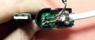
To connect the cable to the power supply for the antenna amplifier, you need to connect the antenna cable to the plug. The first step is to prepare the cable. We retreat one and a half centimeters from the edge of the cable and make a thin circular cut,
How to make your own adapter to supply power to an antenna amplifier
When purchasing an antenna amplifier, it must also be compatible with the receiver as well as the antenna. Impedance, operating voltage and consumption values are taken into account. The necessary adapters and cables are usually supplied. Please note, however, that the antenna booster is not a miracle. If a very weak input signal is present, this may not always be sufficiently amplified by the antenna amplifier.
How does an antenna booster work?
Most devices in this fact with an antenna amplifier have a built-in power supply. The antenna signal booster is placed directly into the socket so that the antenna booster can be supplied with power. In-wall or on-wall amplifiers typically have a power cable that must be routed to the next power source.
Be careful not to damage the fine hairs of the screen under the outer layer of insulation. Remove the cut piece of insulator. Gently and evenly bend the hairs of the screen, it is better to remove the strip of foil. Stepping back 5 mm from the folded edge of the braid, make another circular cut of the inner insulator and remove it. Insert the cable under the fasteners and tighten the screws.
The socket and antenna amplifier must be located near the antenna. If the antenna amplifier needs to enhance digital television, when connecting the antenna amplifier, you should select the socket near the cable socket. The coaxial cable is simply connected to the coaxial cable between the TV and the cable outlet.
What types of antenna amplifiers are available and what are the characteristics of these antennas?
How to connect an antenna amplifier. If there is no jack near the room antenna, an extended antenna cable is required. The following table provides an overview of the different antenna amplifier options. Since antenna amplifiers are usually used constantly, it pays to pay attention to the quality and processing of the amplifier, and this of course affects the price. Therefore, it is better to look for a suitable antenna amplifier in the mid-to-high price segment, which mainly covers its own needs. To do this, it is important to consider in advance how many devices you would like to connect to the antenna booster, just to give an example.
What manufacturers are available for antenna amplifiers
Advantages and disadvantages of antenna amplifiers. Easy installation, no previous knowledge required during assembly required for long cable lengths as the distributor can be used better for TV reception better than radio. There is no guarantee of better reception, the input signal is too weak, the antenna amplifier cannot perform miracles.
- What should you spend on a good antenna amplifier in the purchasing department?
- However, sometimes there are special offers that are cheaper.
As mentioned, the survey results in TV being people's favorite leisure activity at 97 percent, followed by listening to radio at 90 percent.
Please note that the metal braid must touch the bottom tinned area, otherwise power may not be supplied to the antenna. Do not allow the braid of the central core to touch, there will be a short circuit and the 12 V indicator light will not light up.
Much help for this problem is provided by so-called antenna amplifiers. They can be of great help when reception is poor, regardless of the signal. When purchasing an antenna amplifier, you need to pay attention to the good processing and quality of the product, because antenna amplifiers have many years of experience. Therefore, you should look around the mid-price segment for a suitable antenna amplifier. Among the products presented above, the most suitable product should be found for each need.
When purchasing an antenna amplifier, you should consider some points, signal strength, number of possible antenna connections and power consumption. For an antenna amplifier to work well, it must be attached directly to the antenna. Antenna amplifiers are so-called high-frequency amplifiers. They can enhance the power level of the incoming signal. This way, the signal output power becomes greater than the input power, and the images on the TV will be clearer and there will be less interference.
If the power supply for the antenna amplifier is correctly connected to the cable, as well as the cable to the antenna amplifier, then the TV will start showing immediately after setup.
How to connect an antenna television amplifier to a power supply
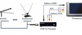
In an area of uncertain reception of a television signal, in order to obtain a high-quality picture when watching television, you have to install an external antenna on the mast, on the vibrator of which an antenna amplifier is additionally installed. Installing an additional amplifier ensures a high-quality picture on the TV when the TV transmission tower is up to 100 km away.
Antenna amplifiers of the SWA line have become widespread due to their high reliability and low price. They are produced for different channel ranges and different gain factors, from 34 to 43 dB in the UHF range and from 10 to 15 dB in the meter range. The photo shows an amplifier type SWA-555/LUX.
The SWA television signal antenna amplifier must be powered with a constant voltage of 12 V. There is a circuit solution that allows supply voltage to the television amplifier via a coaxial cable simultaneously with the television signal. The photo shows how to connect a television wire to the SWA antenna amplifier.
The central core is clamped with one screw, and the shielding wire is stripped of insulation, wrapped and clamped with screws using a strip. The main thing here is to prevent the screen wires from shorting out with the central core. In this way, antenna amplifiers of any type installed directly on the antenna are connected.
There are special power supplies on sale - adapters with adapters that allow you to supply power to the antenna amplifier. There is one of them in the photo. Connecting such an adapter is simple; the cable coming from the antenna is inserted into one coaxial wire, and the cable going to the TV is inserted into the second. The adapter itself is plugged into the socket. It is impossible to mix up the wires when connecting; the coaxial wires coming out of the adapter have different connectors, which prevents erroneous connections.
Power supply - adapter for antenna amplifier
If you open any power supply with an adapter, you will see a power transformer, four diodes, an electrolytic capacitor, a simple capacitor, a choke and a voltage stabilizer microcircuit.
All parts of the decoupling circuit, except the power transformer, are installed on the printed circuit board.
The power supply shown above in the photo - an adapter for powering the antenna amplifier - is assembled according to a classic electrical circuit diagram. AC mains voltage 220 V is supplied to power transformer T1, which lowers it to 12-15 V. The diode bridge VD1-VD4 rectifies the voltage, the electrolytic capacitor C1 smoothes out the ripples, after which a constant voltage of about 16 V is supplied to the integrated voltage stabilizer DA1.
To eliminate video signal losses and loss of DC voltage, an LC filter is provided at the input of the television receiver, made on elements L1 and C3. Choke L1 does not pass a high-frequency television signal to the power supply circuit, but without losses it allows direct current to flow to the central core of the television cable coming from the television antenna amplifier. Capacitor C3 prevents DC current from flowing from the power supply to the TV input, but passes the TV signal without loss.
When making your own power supply with an adapter, parts can be used of any type. Typically, the current consumption of antenna amplifiers does not exceed 150 mA, which is less than 2 watts, so the transformer for the power supply is suitable for any power with an output voltage of 15-18 V. The choke can be made by winding it on a dielectric base, for example, a strip of fiberglass 5 mm wide, 25-18 V. 30 turns of enameled copper wire with a diameter of 0.1-0.5 mm.
Disadvantages of the presented design of the power supply with adapter
The disadvantages of a power supply adapter of this design include the presence of an unshielded section of the central core of the television cable at the place where it is sealed into the printed circuit board, which, in the presence of interference, for example from a working vacuum cleaner, can lead to interference with the video signal. The penetration of interference can be eliminated by installing an additional shield on the printed circuit board at the place where the wires are soldered.
Making your own adapter for supplying power to the antenna amplifier
An adapter with wider technical capabilities can be made with your own hands from any antenna crab-splitter. If you need to power a television amplifier and simultaneously connect several televisions to the antenna, then this is easy to do by adding just three parts to the crab circuit, which will serve as an isolation function.
Design and diagram of the crab
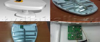
The TV crab is a metal box with F-connectors. Inside, on the central terminals of the connectors, parts (high-frequency transformers) of the television signal splitter are soldered. A high-frequency transformer is shaped like a ring or tube made of ferrite with a magnetic permeability of 600-2000, on which 1 to 10 turns of enameled wire with a diameter of 0.2-0.3 mm are wound, evenly spaced around the entire circumference.
In the photograph of the crab from which the back cover has been removed, you can clearly see how the ferrite transformers are wired for connecting three TVs. This crab is assembled according to the Electrical Circuit Diagram below.
All produced crabs are assembled according to the given electrical circuit diagram; there may be minor deviations - additional separating and filtering capacitors, chokes, and matching resistors are installed.
When making an adapter for supplying power to an isolated antenna amplifier, I decided not to install an additional connector for connecting the power supply, but to use one of the connectors for connecting the F-plug. To do this, we had to remove one of the transformers, limiting the crab's ability to connect only two TVs.
As a result of the modification, only two TVs can be connected to the crab, and its circuitry has changed.
All that remains is to install the LC filter in the crab and the adapter will be ready for use. Since the crab body is made of duralumin, the capacitor lead had to be connected to it through an additionally installed brass terminal, screwed to the adapter body using a screw and nut with a shaped washer.
As a result of the modification, the electrical circuit diagram of the crab acquired the following form. As can be seen from the diagram, transformer T1 remained original, but a choke and two capacitors were added.
To better match the circuit, you can solder a 150 Ohm resistor between the output pins XW2 and XW3. You can install the adapter in any convenient place, directly next to one of the TVs, or, for example, at the cable entrance to the apartment. If you need to connect only one TV, then transformer T1 can be removed, and the right terminal of capacitor C1 can be soldered directly to the central terminal of one of the connectors XW2 or XW3, to which the cable going to the TV can be connected.
Connecting the power supply to the adapter
Since I decided to connect the power supply to the crab through one of its F-connectors, to implement this idea I had to make an adapter from an ordinary double wire coming from the power supply to a coaxial cable.
To do this, you need to take a piece of antenna cable 5 cm long, cut one end of it and put on an F-wrap. To the second end, as shown in the photographs, solder the wires coming from the power supply with a shift. The positive terminal is soldered to the central core of the antenna cable.
If you don’t want to mess around, you can install a standard connector in the crab body for connecting power supplies and through it supply voltage to the antenna amplifier through a home-made adapter.
ydoma.info
Malfunctions
The main malfunctions of the antenna power supply include:
- Transformer malfunction;
- Stabilizer malfunction;
- Filter malfunction.
During voltage surges or overload in the secondary circuit, the fuse built into the primary circuit of the transformer may blow. This can be determined by measuring the resistance on the power supply plug. The absence of resistance may indicate a faulty fuse or a break in the primary winding of the transformer. To check the fuse, you need to cut the insulation on the transformer under which the fuse is located and check it for integrity. The fuse is usually located at the point where the network wires enter the insulation.
Improve reception with an antenna booster
An antenna amplifier can be used to compensate for distortion and line loss.
If you have any questions, don't hesitate to contact us by phone or email. An antenna amplifier is an electronic device that amplifies signals in the high frequency range. The devices cover different frequency ranges. Multipliers are used directly after the antenna or in their vicinity, and the antenna cable leads the antenna cable to consumers such as television or radio. If the stabilizer malfunctions, the supply voltage of the antenna amplifier can either decrease or increase and lead to failure of the amplifier. This can be determined by measuring the voltage at the output of the power supply.
Failure of filter capacitors can result in significant image noise. The most common is the appearance in the image of 2 - 3 horizontal, wide black stripes, slowly moving across the screen.
There are also antennas that have already integrated an amplifier, then this is the so-called active antenna. The installation and use of antenna amplifiers is very simple, only the lengths of the transmission distances need to be taken into account. Our devices have an external power supply, so no current needs to be transmitted through the antenna. Gain is expressed in decibels in increments of less than 10 to more than 30. If the reception signal on your TV is too weak, a suitable antenna booster with the appropriate decibel number will help.
But we also offer innovative products in the smart home segment. Our product segments are always in line with current technological trends. As always, when an analogue television channel was misinterpreted, at some point the question arose: “Is this solved with an antenna booster?” But the previous question still comes up in conversation.
As with any device, the operating life of the antenna amplifier power supply is limited. Should I turn off the antenna amplifier's power supply? If you are leaving for a long time, then yes it is necessary, but you should not turn it off every time you turn off the TV. As you know, most breakdowns of electrical appliances occur precisely at the moment of turning them on and off, and turning them off once again will not extend the service life of the antenna power supply, but they are quite cheap so that it is better to buy a new one later.
Generally speaking, it is a device that receives an input signal that "amplifies" or amplifies it to a greater or lesser extent using a regulator to improve the output power. If the antenna does not receive it well, it will “amplify greatly.” First and foremost would be to change the cable for better quality. It must be said that many problems are solved by replacing the cable carrying the signal. In fact, what is received by the antenna reduces its power when transported to the TV, although these losses are not very important in the vast majority of cables.
Having a country house or dacha, everyone, sooner or later, thinks about how and where to place the television antenna and cable, which always gets in the way when cleaning. Once the decision has been made, other tasks arise. Which antenna to choose, with an amplifier or a regular one? Will there be more TVs in the house? Do I need a splitter? Lay the wire in the baseboard or drill into a wall or window frame, etc. It’s good if you decided on the first two questions, chose an antenna with an amplifier and decided to provide several points for connecting the TV.
But if you don't want to change the cable, there is no other choice than to go for an amplifier. Where should the amplifier be located? There is no other solution to this: as close to the antenna as possible. By putting it at the output end of the signal, usually where we have a problem, the east continues to persist because what is achieved is to provide both the signal and the problem. Remember that boosting a TV signal doesn't mean improving it unless you improve its transport power using a medium, in this case cable.
What would be the best amplifier? Here begins the time of propaganda without paying for it: the one that suits best are those that consist of two parts, one external and the other interior, connected to the electrical network, and which supplies current to the outdoor unit and to the antenna.
Why is the signal weak?
First, let's look at the possible reasons for this problem - there are a number of them:
- Bad equipment. It happens that everything is fine with the signal transmitted by the repeater, it reaches directly without obstacles, but the receiving device itself is old or simply of poor quality.
- Another problem is the cable: too long or too high resistance (or both).
- The range of the nearest tower. The signal weakens with the distance traveled - this problem is often faced by residents of remote areas.
- Obstacles. The digital wave is sensitive to objects that are opaque (to itself), because cannot bypass them: terrain features, brick fences, buildings, dense tall forests greatly affect the quality of the transmitted message.
- Increased humidity or “dusty” air also tends to scatter the signal, which is why it reaches the antenna in a distorted form.
- The signal that the receiving device receives is reflected - there is never any loss of quality here.
As you can see, most often it is difficult to influence this situation directly, unless, of course, you have the opportunity to erase all the hills and buildings between your house and the repeater.
How to boost the signal
Of course, no matter how weak the signal is, it does not affect the user’s desire to enjoy watching digital television. You need to look for a way to solve the problem - one of the following will do:
- Replace the antenna with a better one. Even if this is not the main problem, choosing a more powerful device often helps - sometimes even enough that additional action is not required.
- Look for the best antenna location and direction. In an ideal scenario, digital antennas are mounted as high as possible and oriented towards the nearest repeater - with the latter being especially important. When it comes to UHF waves, even a small angle of rotation significantly changes the quality of the signal. If you don't know where the nearest tower is, look on a map online.
- Try using a cable with less resistance, especially if the distance between the antenna and the TV is quite large. This will reduce transmission losses.
- Alternatively, you can try to change the location of the devices themselves so that they are closer to each other - and use a cable that matches the new distance. The general rule is: the less the signal has to overcome, the better.
- Ultimately, if none of the previous ones worked (or worked, but not to the extent that we would like), you can resort to another method - an antenna amplifier.
It is at this stage that the user immediately has many other questions: what is an amplifier, will it help, how to connect it. We'll figure out.
Antenna installation
Our choice fell on the Delta series antenna with an amplifier. The distance to the city is 60 km and the image quality is far from ideal. To operate the amplifier, you need a 12-volt power supply and a special connection circuit with power supply via an antenna cable. The antenna manufacturer will provide every buyer with all this. But if you say that you want to add a splitter, then most likely you will be offered a splitter with the ability to connect to your antenna, but it will cost several times more. And not everyone knows in advance that a regular splitter will not work :).
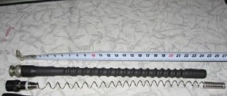
The antenna mount itself is individual and depends on the shape and height of the roof. The antenna in our solution is mounted on a long pipe. The tube is attached at three points to the wall of the house. The pipe is composite and disassembling it if necessary is not difficult.
After connecting the wire, for safety reasons, I recommend wrapping the coaxial cable itself with a piece of thin rubber hose, at the point of contact with the edges of the hole or at the bend when entering the attic or room.
This will protect it from breaking or chafing at the bend.
Amplifier purpose
Reliable reception of programs for viewing channels on terrestrial television using a conventional antenna is only possible at a short distance from the transmitting center. In all other cases, the active antenna is supplemented with a reception amplifier. As an example, we can cite Polish antennas, which have become very widespread, and Delta-type antennas.
Polish antenna
Antenna Delta
The main function of TV antenna amplifier:
- increasing the level of the useful signal to acceptable values;
- reduction of interference level.
These qualities are listed because the quality of reception is affected not only by the magnitude of the useful signal, but also by its relationship to the level of interference. Based on this consideration, the antenna amplifier is located in close proximity to the antenna, often entering directly into its structure.
The power supply voltage for the antenna amplifier is supplied through the antenna cable. To isolate the useful signal, an antenna, either Delta or any other, is connected to the TV via an adapter. Some TV or tuner models have an antenna socket that already contains voltage. Thus, the need for a power supply and adapter is eliminated, although this does not exclude the possibility of using them. To do this, there must be an item in the TV settings menu that allows you to turn off the antenna power through the antenna input.
Important! The simultaneous supply of power from the antenna socket and the external power supply is not allowed, as this may lead to failure of one or more devices. At best, the quality of reception will suffer.
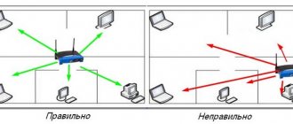
Installing a splitter
Choose a location for installing the splitter in the living room or in the attic, the main thing is that there is an outlet nearby. If the wiring diagram allows you to run an outlet with a switch into the attic, then I think that is the best option. It is possible without a switch, but I prefer to turn off the antenna while leaving. Still, the antenna is not a refrigerator, so it’s better not to waste electricity. And don’t forget about safety.
The outputs of the splitter connect cables going to the TVs in your home. You can try connecting an antenna cable to the input of the splitter, but in my case, nothing worked without an amplifier; the TV only showed ripples.
Basic faults
DIY power supply for 12V screwdriver
Amplifier power supplies rarely fail so much that they cannot be repaired. The most common loss of filter capacitance is observed. This malfunction manifests itself in the form of wave-like image distortions due to the penetration of voltage ripples into the amplifier and antenna input of the TV. The reason is usually a poor quality capacitor. Externally, it will have a convex end (must be flat). For repairs, it is enough to install a similar one with a capacity of 220-500 µF at a voltage of 35-50 V.
The absence of output voltage when there is a stabilizer chip at the input indicates a malfunction of the latter. For replacement, you can install any similar microcircuit (analogues were indicated above).
In cases of network voltage surges, the step-down transformer fails. Unfortunately, repairing it will require rewinding the windings, which is difficult to do at home. But if the transformer windings are made on separate coils, then it is possible not to resort to rewinding. Typically there is a fuse built into the primary circuit. To get to it, you need to carefully, trying not to damage the conductors, cut off the outer insulation of the primary winding, which is wound with a thin wire and has a large number of turns, and therefore is much larger than the secondary. A fuse looks like a resistor and if it blows, it has infinite resistance (a working fuse has zero resistance). A faulty fuse is bridged with a thin wire with a diameter of 0.05-0.07 mm.
The diode bridge is made on rectifier diodes with a large margin of voltage and permissible current, so it almost never fails.
Much more often, the junction between the cable and the adapter becomes loose, resulting in loss of contact with the central core, or short circuit with the shielding braid. In this case, you need to connect the antenna cable efficiently and reliably.
To summarize, we can say that most consumers should not see a problem in how to properly connect the power supply or even repair it themselves. The most important thing is attentiveness, accuracy and desire.
Connecting the amplifier power supply
If you leave the circuit when the power supply is connected directly in front of the TV, then nothing will come out through the splitter in the opposite direction; the current to power the antenna amplifier will not pass. Therefore, you need to make an adapter or buy it if you thought about it in advance, before arriving in a remote locality.
To create the adapter, I used a piece of old-style coaxial cable, it is thicker and easier to solder. A plug for connecting to a splitter and a connector from an old TV.
How to connect an antenna television amplifier to a power supply, instructions
There are places where the television signal arrives in very low quality. In such cases, you have to use an external antenna, on the vibrator of which the antenna amplifier is located. It allows you to strengthen the signal even at a distance of 100 km from the tower.
Widely used amplifiers are SWA amplifiers. They have a low price and provide sufficient reliability. They have different gains and are designed for different ranges of channels. In the decimeter range, the gain is 34-43 dB and 10-15 dB in the meter range. In the photo below you can see the amplifier model SWA-555/LUX.
The SWA signal amplifier operates from a constant 12 V power supply. There is a circuit that allows voltage to be supplied to the amplifier via a coaxial cable along with the signal. On the market you can find an adapter that is also a power supply that solves the problem. It is shown in the photo below.
Connecting the adapter does not require any skills. We insert the wire that goes to the TV into one coaxial cable, and the antenna wire into the other. The adapter is installed into the outlet. It is not possible to mix up the wires, since there are different connectors at their ends.
Power supply - adapter for antenna amplifier
By opening the power supply with the adapter, you can find a power transformer, simple and electrolytic capacitors, 4 diodes, an inductor, and a microcircuit that acts as a voltage stabilizer.
Everything except the transformer is located on the printed circuit board.
Electrical circuit diagram of the power supply with adapter
The adapter shown in the photo above is assembled according to the classical scheme. The alternating voltage of the 220 V network is supplied to T1 (transformer), which in turn reduces it to 12 V - 15 V. VD1-VD4 (diode bridge) will perform the function of a voltage rectifier. To smooth out ripples, capacitor C1 is used. After which a constant voltage is obtained, the value of which is about 16 V. Then it goes to DA1 (integrated stabilizer).
An LC filter is made on elements C3, L1. It is installed at the receiver input. It eliminates the loss of DC voltage and loss of video signal.
L1 (choke) prevents the high-frequency signal from flowing into the power supply circuit. At the same time, direct current flows freely to the central core of the TV cable, which comes from the amplifier. C3 (capacitor) prevents DC current from flowing from the power source to the TV input. There is no signal loss in this case.
To make your own power supply, you can use various types of parts. Any transformer can be used with an output voltage of 15-18 V. This is due to the fact that the antenna amplifier does not exceed a current consumption of more than 2 W and 150 mA. As a choke, you can use a piece of dielectric, for example textolite, the width of which is 5 mm. From 25 to 30 turns of enameled copper wire are wound around it.
Disadvantages of the presented design of the power supply with adapter
One of the disadvantages is the presence of a section that does not have a screen on the central core of the television cable. This area is located at the soldering point with the printed circuit board. When operating equipment such as a vacuum cleaner, this may cause interference to the video signal. This can be avoided by installing an additional screen.
Making your own adapter to supply power to the antenna amplifier
If you need an adapter - an adapter that has wide technical capabilities, you can make it at home from a crab antenna splitter. To power the amplifier and additionally connect several TVs to the antenna, the crab circuit will have to be supplemented with 3 parts.
Design and diagram of the crab
The TV crab is a metal case with F connectors. High-frequency transformers for the TV signal splitter are wired inside it. They are located on the central terminals. The high-frequency transformer looks like a tube or ring made of ferrite. It has a magnetic permeability of 600-2000. Turns of enameled wire are wound on top, the diameter of which is 0.2 mm–0.3 mm. They are located evenly around the entire circumference. The number of such turns can reach from 1 to 10.
The photo shows a crab. The back cover has been removed. As you can see, the ferrite transformers are wired in order to connect 3 TVs. It was manufactured according to the electrical circuit diagram shown below.
All crabs are made according to this pattern. It may have some deviations - installed chokes, resistors, filtering, decoupling capacitors.
How to make your own adapter to supply power to an antenna amplifier
In order to make an adapter designed to supply voltage to the antenna amplifier, I did not install a connector under the power supply. I decided to use one connector to connect the F-plug. To do this, it was necessary to remove one transformer. The number of connected TVs has decreased to two.
As a result, the concept has undergone changes.
Crab diagram for two TVs.
Before using the adapter for its intended purpose, you should install the LC filter in the crab. The crab body is made of duralumin, so I made a brass terminal. It was secured to the body using a screw and a shaped nut.
As a result, the scheme changed slightly. Transformer T1 remained in its place, 2 capacitors and a choke were added.
To match the circuit, it is advisable to install a 150 Ohm resistor between the output pins XW3 and XW2. The adapter can be installed in any convenient place. Both at the cable entrance to the apartment and near the TV.
If you only use one TV, T1 can be removed from the circuit. Solder the right pin C1 (capacitor) to the central pin of connector XW3 or XW2. The cable will be connected to the connector to which the capacitor will be soldered.
Connecting the power supply to the adapter
I previously wrote that I want to connect the cable via the F connector. Therefore, from the double wire that came from the power supply, I made an adapter to a coaxial cable.
To implement this idea, you will need to take an antenna cable about 5 cm long. Then cut it to make one end and put on an F - wrap. The photo shows further steps. We take the wires that come out of the power supply and solder them with a shift to the second end of the cable. “+” must be soldered to the central core of the antenna cable.
If you do not want to perform these operations, you can install a connector in the crab body to which the power supply will be connected. And through it, voltage will be supplied to the antenna amplifier through the adapter that we made.
Based on materials from the site: ydoma.info
www.proterem.ru
Assembly and enjoyment
Let's collect all the details in one place. Here is a list of all circuit components used:
- Antenna with built-in amplifier;
- Antenna cable to the amplifier power supply plug;
- Adapter from antenna connector to splitter plug;
- Splitter, the most common;
- Coaxial cable and plugs for connecting to TVs.
The connection option shown on the right allows you to connect several TVs using one power supply, the most common splitter and an antenna with an amplifier.
Satellite TV
In order for the antenna amplifier installed in the “Polish Grid” antenna housing to work, it must be connected to a power source. The amplifier is powered via a coaxial cable running from the antenna to the TV. This means we need to connect the power supply to this cable. Many users find it difficult to do this. Let's consider a simple connection option.
| The power supply is a converter of high voltage household electricity to low voltage. This voltage is used to provide power to the electrical circuit components. It also serves to stabilize and protect the supply voltage. |
First you need to cut the end of the television cable (more about cutting the cable). We step back 1.5 cm from the end of the cable and carefully remove the outer insulation, trying not to damage the screen and the insulation of the central core. Remove the outer shell cut in a circle. Then we move the hairs of the screen and the foil back. Next, we retreat 0.5 cm from the moved braid and cut off the inner insulation from the central core in a circle. The cable is ready for connection.
Carefully place the cut cable into a special fastener on the power supply separator board. It is necessary that the cable braid tightly touches the lower contact pad, and the central core is inserted into the screw retainer.
We tighten the screws until the cable contacts are completely fixed.
| It is necessary to ensure that the central core and the braid do not touch under any circumstances, otherwise we will get a short circuit and the system will not work. In this case, the indicator on the power supply will light very dimly or not light at all. You also need to ensure that the braid is in close contact with the pad on the board. Otherwise, the voltage may not flow through the cable. |
If connected correctly, the TV will begin to show channels when scanning and tuning them. If you turn off the power supply, the image may deteriorate or disappear altogether.
Happy connection!
9, total, today
Please give us your valuable comments
digitalsattv.ru
With your own hands
The above circuit consumes excessive current from the network. If you modify it, you can end up with a more economical power supply with improved characteristics. Here is a diagram of an economical power supply for an antenna amplifier:
Resistors R1, R2 reduce the power supply's own consumption, the operating voltage of the problematic capacitor C5 has been increased, and additional filters L1C7 and L2L3C8 have been added.
There is nothing difficult about making a power supply for an antenna amplifier with your own hands. It should be remembered that a homemade antenna power supply must have low consumption and good stabilization, otherwise interference in the form of snow, slanting stripes and wide black stripes will appear on the screen.