Why is grounding necessary?
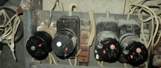
If the energy supply in the room is organized in accordance with the PUE, circuit breakers are installed at the entrance, in the distribution panel.
These switches are triggered when the set current strength is exceeded: the bimetallic plate heats up, it deforms, and the contacts of the machine mechanically open.
Important! It is for this purpose that the machines are installed in the phase conductor gap. The zero bus can be connected directly.
When a live circuit breaks, the electrical installation (or the entire circuit) is de-energized, ensuring safety. How does this work in practice, and what is grounding in this chain?
Grounding is an electrical contact between a line specially allocated in the electrical network and the real (physical) ground. That is, the grounding bus has electrical contact with the ground. At the same time, any installation that generates or distributes electric current is connected by a neutral wire to the same ground.
We are considering single-phase networks in which two lines are used for power supply: zero and phase. Three-phase systems are rarely used in everyday life, so knowledge of these systems is necessary only for professionals.
Even if three phases are installed in your house (this occurs in the private sector), for final consumption two wires are still used: zero and phase.
Let's say your electrical installation (refrigerator, boiler, washing machine), especially with a metal body, has a phase leak. That is, the live wire touches the housing (the contact is disconnected, the insulation is broken, water leaks). If you touch an electrical appliance, you will receive an electric shock. In addition, the resistance at the point of contact is negligible, as a result of which the wire will instantly heat up and the electrical appliance will ignite.
If your boiler is grounded, the electric current will flow along the path of least resistance, that is, along the circuit: phase - “ground” - zero bus. The current will spontaneously increase and an emergency shutdown will be triggered in the circuit breaker. No one will get hurt, no material damage will be caused.
If you have a superficial knowledge of electrical installations, the question arises: why do you need grounding if the same thing happens between the phase and neutral wires? And actually, what is the difference between grounding and grounding?
Grounding. What to do if the supply line is two-wire
In this article we will examine in detail the question of how to correctly connect an RCD (Residual Current Device) in a two-wire power supply system.
In our work, we often have to deal with a situation where electrical equipment at a facility is not completely grounded, or is not grounded correctly.
Most often this occurs in apartments, residential buildings, offices and shops that are located in old buildings where the wiring has not been changed for decades.
At some facilities, all wiring is made with two-wire wires (or four-wire for three-phase consumers), that is, there is no third (or fifth for three-phase networks) protective grounding conductor. In this case, everything is immediately clear. Verdict - the equipment is not grounded.
In other cases, internal wiring is done as required with three-core cables (five-core for three-phase equipment) and all electrical installations and electrical installations (sockets) are connected to a protective grounding conductor.
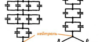
Let's analyze the situation with diagrams
From the point of view of the flow of electric current, there is no difference between grounding and grounding. The neutral wire in any case has electrical contact with physical ground.
Accordingly, when a phase is shorted to the housing, the same short circuit will occur and the circuit breaker will turn off. Of course, (subject to proper connection: the socket must have a third ground contact, just like an electrical appliance. For this reason, electricians, violating the requirements of the Electrical Installation Rules, often separate the ground bus from the zero contact of the input panel.
Let's imagine a situation where the neutral wire is broken for some reason:
- loss of contact due to corrosion (in old high-rise buildings this is a working situation);
- mechanical rupture of the cable due to repair work with violations of technology (unfortunately, also not uncommon);
- unauthorized intervention by a home-grown “electrician”;
- accident at the substation (only the zero bus may be disconnected).
In the diagram it looks like this:
When organizing protective grounding, the electrical circuit between the physical “ground” and the grounding contact of the electrical appliance is broken. The installation becomes defenseless. In addition, a free phase without a load can create a potential equal to the input voltage at the nearest substation. Typically this is 600 volts. You can imagine the damage that will be caused to the electrical equipment that is turned on at this moment. In this case, there is no current leakage to the physical ground, and the circuit breaker will not trip.
Imagine that at this moment you simultaneously touch a phase (a breakdown on the body of an electrical installation) and a metal object that has a physical connection with the ground (a water tap or a heating radiator). You can get electrocuted at 600 volts.
Now let's see what the difference is between grounding and neutralizing (in our diagram). If the zero bus breaks, the power to all electrical installations in this circuit will simply disappear. There will be no electric shock under any circumstances: the electrical circuit between the physical ground and the grounding contact of electrical appliances is not broken. We have already preserved our health. Now let's see what happens to electrical installations. The maximum damage is a burnt-out incandescent lamp closest to the input panel. Moreover, trouble will only occur if the voltage on the phase wire increases. The current strength will increase (according to Ohm's law), the circuit breaker will work, and perhaps other electrical appliances will not be affected.
It is for this reason that the PUE strictly prescribes: protective grounding and grounding of electrical installations must be organized independently of each other, using different lines.
For reference: Wire color coding is usually used:
- The phase is brown or white.
- The working zero is blue.
- Protective grounding is a yellow-green shell.
If you have a modern home, then grounding and grounding are carried out in accordance with the Electrical Installation Rules. This can be easily checked by looking at the input cable in the panel. In addition, you can check the correct connection yourself.
Species and types
Modern manufacturers offer a variety of types and types of RCDs. The two most popular types of units in terms of their internal design on the electrical goods market are electromechanical (do not depend on current) and electronic (depend on). Selective and fire-fighting devices are also distinguished.
Electromechanical
Electromechanical RCDs are widely used and are used in AC electrical circuits. What causes this? The fact is that when a leak is detected, such a device will work, preventing dire consequences even at the smallest voltage.
This type of RCD in many countries is considered a standard of quality and one that is mandatory for widespread use. No wonder, because such an RCD will be operational even if there is no zero in the network and can save someone’s life.
Electronic
Such RCDs are easy to find on any construction market. The difference between them and electromechanical ones is that they are located inside the board with an amplifier, which requires power to operate.
However, such RCDs, as already mentioned, have a huge drawback - it is not a fact that they will operate in the event of a current leak (it all depends on the voltage in the network). If the zero burns out, but the phase remains, then the risk of electric shock does not go away.
NOTE! We are talking about the advantages and disadvantages of RCDs in general, and not specific models. If you are very lucky, you can become the owner of a low-quality RCD, both electromechanical and electronic.
Selective
The main difference between selective RCDs and their “brothers” is the presence in the circuit of a time delay function for turning off the circuit that powers the load, i.e. selectivity. Often this parameter does not exceed 40 ms. From this we conclude that selective devices are not suitable for protection against injury from direct contact.
Another feature of selective units is their good stability in response to current and voltage surges (the probability of false alarms is almost zero).
Fire protection
As the name suggests, such RCDs are used in the power supply systems of apartments and houses to prevent fires. However, they are not able to protect a person since the leakage current for which they are designed is 100 or 300 mA.
Typically, these units are installed in metering panels or in floor distribution boards. Their main task:
- input cable protection;
- protection of consumer lines in which differential protection is not installed;
- as an additional level of protection (if the device below it suddenly does not work).
Number of poles
Since the RCD works by comparing the currents that penetrate through the differential element, the number of poles of the unit coincides with the number of current-carrying conductors. In some cases, RCDs can be used with 4 poles to operate in a two- or three-wire network.
At the same time, do not forget to leave free phase poles in reserve. The unit will successfully do its job not completely, but partially, which, in general, is unprofitable from a financial point of view, but possible.
Every day more and more household electrical appliances appear in our lives. Accordingly, the risk of current leakage increases, which sometimes even leads to death. Even if it doesn’t kill you with an electric shock, it will cause serious health problems or cause a fire. There is one salvation from all these troubles - a protective shutdown device. We strongly advise you to install it at home, as they say, out of harm’s way.
How to distinguish between working zero and protective grounding
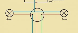
Of course, you should not check the resistance between the “neutral” and “ground” wires, especially if the power system is energized. No one will let you into the common control room either. Therefore, we will check the correctness of the separation of zero and ground using a multimeter (household tester).
Since the input points of grounding devices (zero at the substation and the grounding bus in the house) are located at a distance from each other, there is a certain resistance between them. The soil, even wet, is not an ideal conductor. If we organize an electrical circuit without a load, we will see the difference in potentials.
We connect the measuring device to the phase contact and the working zero. In the diagram this will be circuit “A”. We fix the value.
We immediately connect the tester to the phase wire and the protective zero contact. In the diagram this is circuit “B”. There is no difference in potential: the device will record the same voltage value. Why did it happen? When the working and protective zeros are combined, the current in both measurement options actually flows through the same wire. The resistance does not change, there are no losses, and there is no voltage drop.
If your measurement results show the same voltage, the wiring is connected in violation of the Electrical Installation Rules.
Test method
Before checking the serviceability of the grounding, you should determine the neutral and phase wires using an indicator screwdriver. After contact with one terminal, the light in the screwdriver lights up - this is phase, if it does not light up - zero. The presence of grounding, even with a three-wire wire, must be checked using simple methods: using a multimeter or a tester.
Checking with a multimeter
- turn on the power supply in the room (house) at the distribution board;
- measure the voltage in the socket by setting one probe to phase and the second to zero;
- move the contact sensor probe from zero to the grounding conductor (PE);
- check the tester's readings; if they have remained virtually unchanged, it means the grounding system is in order; if the readings are at zero, the system is not working.
Checking with a control light
To build a device called a “control,” you need to take a light bulb with a socket and connect two copper wires to it. In this case, the contacts of such a tester must be isolated between all elements. Testing with a test light is carried out in the same way as with a multimeter: one probe is connected to zero, the second to phase. Then the probe is moved from zero to the ground connection.
If the wiring does not have color recognition, you can determine the phase and zero in this way: attach one limit switch to the ground terminal, and the second one alternately to the first and second connections. The phase is located where the light source will light up. If the light does not light, it means that the PE circuit is not functioning.
In the case when the lamp does not light when the phase and neutral are connected, you need to check the contacts of the device, and also whether the lamp has burned out and whether there is power in the distribution board. Sometimes the reason the lamp does not light up is that there is a break in the neutral or phase circuit.
When research with devices does not show an absolute guarantee of connection, it is necessary to open the outlet and check the conductors. To do this correctly, you need to follow the instructions:
- Check the voltage by plugging in one of the appliances (table lamp, iron, etc.). In this case, you must not touch the grounding contact.
- Turn off the power at the distribution panel and remove the plug from the socket.
- Remove the socket cover and check the tightness of the wires, and also see what the ground pin is connected to. If it is connected to one of the socket terminals, it is grounded. Connecting to a separate wire indicates that grounding is being used. Lack of connection is a factor of lack of grounding.
- Place the cover in place, secure it and turn on the machine on the panel.
When working with the electrical network, we must not forget about safety rules. Be sure to check the serviceability of all devices. Do not touch the conductor with wet hands or stand on a wet floor. You cannot make a PE loop between the grounding contact and the neutral terminal, this can lead to a fire after the neutral conductor breaks. The best option is to call a professional electrician.
You should definitely check the PE circuit if: you hear noise while playing music or feel slight electric shocks when using household appliances such as a kettle, water heater, washing machine or dishwasher. Such factors are a sign that the PE system is not functioning at all or is working poorly.
But what if your house does not have protective grounding at all?
It is clear that when carrying out major repairs, electricians will replace the wiring in accordance with the Electrical Installation Rules. At a minimum, three independent wires will appear in your input panel: phase, working zero and protective ground. All that remains is to replace the wiring in the outlet network.
But major repairs can be carried out in a few years, and today you are already using a boiler and washing machine without grounding, or even worse - with a protective grounding. There is only one way out: organize grounding yourself. If you live in a private house, the technical side of the issue is significantly simplified. But for high-rise buildings, the cost and complexity of the work depends on the floor.
An alternative is to organize a grounding bus with your neighbors, with junction boxes on each staircase.
The tire must be one-piece until it is inserted into the ground. Near the foundation, preferably not in the road surface, but in a flower bed, a grounding loop is organized in accordance with the Electrical Installation Rules. Each resident of the entrance can connect to the common bus and bring “ground” into the apartment. Then there are two options:
- Organize a grounding contact group in the distribution panel, and replace all electrical wiring with three-wire wiring.
- Inside the baseboard, stretch the earth cable under each socket and insert it into the mounting boxes.
Either way, you will protect both your electrical appliances and, most importantly, your health.
Installation of a built-in socket with grounding
At the first stage, a socket box is installed, which can be represented by models for plasterboard or concrete walls. The room is de-energized, after which the following actions are performed:
- the socket box is placed in a standard size hole made in advance in the wall;
- structures for plasterboard walls are fastened with self-tapping screws and plastic clips, and for concrete, a freezing method is used using alabaster or other plaster mixtures;
- the insulating part of the wires coming out of the socket box is stripped one centimeter;
- unscrew the screw and remove the cover from the base;
- the wires are screwed onto the terminals.
The order of connections must be strictly observed. First, the grounding connection is made, then the “zero” and the remaining “phase” are connected.
The grooves in the wall for the electrical wire are made with a hammer drill and have a depth and width of 2.5 cm.
Video on the topic
Source: profazu.ru
My bitter experience as an electrician allows me to say: If your “grounding” is done correctly - that is, in the panel there is a place for connecting "grounding" conductors, and all plugs and sockets have "grounding" contacts - I envy you, and you have nothing to worry about worry.
Grounding connection rules
What is the problem, why can’t you connect the ground wire to heating or water supply pipes?
In reality, in urban conditions, stray currents and other interfering factors are so great that anything can end up on the heating radiator. However, the main problem is that the tripping current of the circuit breakers is quite high. Accordingly, one of the options for a possible accident is a short-circuit breakdown of a phase to the housing with a leakage current just somewhere on the border of the machine’s operation, that is, at best 16 amperes. Total, we divide 220V by 16A - we get 15 ohms. Just some thirty meters of pipes, and you get 15 ohms. And the current flowed somewhere, towards the uncut forest. But that doesn't matter anymore. The important thing is that in the neighboring apartment (which is 3 meters away, not 30, the voltage on the tap is almost the same 220), but on, say, a sewer pipe there is a real zero, or so.
And now the question is - what will happen to the neighbor if he, sitting in the bathroom (connected to the sewer by opening the plug) touches the tap? Did you guess it?
The prize is prison. Under an article about violation of electrical safety rules resulting in casualties.
We must not forget that you cannot imitate a “grounding” circuit by connecting the “zero working” and “zero protective” conductors in a European socket, as some “craftsmen” sometimes practice. Such a replacement is extremely dangerous. Cases of burning out of the “working zero” in the shield are not uncommon. After this, on the body of your refrigerator, computer, etc. 220V is placed very firmly.
The consequences will be approximately the same as with a neighbor, with the difference that no one will be held responsible for this except the one who made such a connection. But as practice shows, this is done by the owners themselves, because... They consider themselves sufficient specialists not to call electricians.
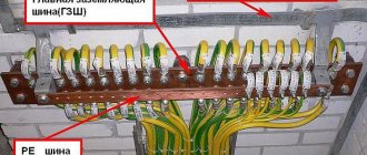
"Grounding" and "grounding"
One of the options for “grounding” is “grounding”. But not as in the case described above. The fact is that there is a zero potential on the switchboard body on your floor, or more precisely, the neutral wire passing through this very switchboard simply has contact with the switchboard body through a bolted connection. Neutral conductors from the apartments located on this floor are also connected to the shield body. Let's take a closer look at this point. What we see is that each of these ends is threaded under its own bolt (in practice, however, these ends are often connected in pairs). This is where we need to connect our newly made conductor, which will later be called “grounding”.
This situation also has its own nuances. What prevents the “zero” from burning out at the entrance to the house. Actually, nothing. We can only hope that there are fewer houses in the city than apartments, and therefore the percentage of occurrence of such a problem is much lower. But this is again a Russian “maybe”, which does not solve the problem.
The only correct decision in this situation. Take a metal corner 40x40 or 50x50, 3 meters long, hammer it into the ground so that they don’t stumble over it, namely, dig a hole two shovel bayonets deep and drive our corner there as much as possible, and from it draw a PV-3 wire (flexible , stranded), with a cross-section of at least 6 mm. sq. to your switchboard.
Why is the TN-C system obsolete?
Much of modern technology uses switching power supplies.
These devices have filters against RF interference. These are small capacitors that connect the circuit to the metal case and the ground pin of the plug. Interference coming from the electrical network or occurring during the operation of electrical equipment through the capacitor and ground wire “goes into the ground” and does not disrupt the operation of devices connected to the power supply.
Under normal conditions, the current passing through the filter is not sufficient to trip the RCD or electrocute a person, but if this capacitor breaks down, the housing is connected to a 220V network. This situation is not dangerous if there is a grounding system that complies with the requirements of the PUE, but can lead to electrical injury if it is absent or the TN-C system is used.
The situation of a break in the neutral wire “N” is also dangerous. In this case, the housing will be energized through the “phase-electrical device-zero-grounding-body” circuit.
A similar situation occurs when a leak occurs in a washing machine or dishwasher or a heating element burns out in a boiler.
| The main disadvantage of the TN-C system is the appearance of a dangerous potential on grounded equipment housings when the PEN conductor burns out. That is, in cases of PEN conductor breakage, grounding (grounding) loses its protective properties. |
Dangerous grounding methods
In order to protect themselves and their family members from electric shock, some “experts” lay the grounding line themselves. Various options are used for this:
- Connection to central heating radiators or water pipes. This is dangerous because if there is a small leak, current will begin to flow through the pipes, causing rapid corrosion, and plumbers may suffer electrical injury during repairs.
- Connection in the socket of the neutral and ground contact. This is not grounding, but grounding. In the PUE clause 1.7.50, grounding is not included among the means that protect against electric shock.
- Connecting the PE protective conductor to the electrical panel housing located on the floor. This option is better than the previous ones, but the quality of the connection between the PEN wire itself and the shield body is unknown. In addition, the junction of the “PEN”, “N” and “PE” wires must be grounded.
In addition, it is not known whether the PEN conductor in the floor panel is grounded at all. For example, one can imagine a situation where, with such a “grounding scheme,” the neutral wire N breaks, and then all the grounded housings of devices in the apartment through this additional PE conductor will be energized.
Moreover, if you look at it, such a connection is not grounding, but grounding.
In addition to various options for independent connection to the “PEN” wire, it is possible to install a grounding loop from steel corners, pins and pipes buried below the soil freezing level. A wire is connected to these corners, brought into the apartment and connected to sockets. In this case, there is a danger of this wire breaking or oxidizing at the contact point located on the street.
Important! The grounding loop, carried out in accordance with all the rules, is connected by electric welding to the metal elements of the building structure and is subject to regular inspection. The only reliable protection against electric shock is the installation of TN-CS or TN-S grounding systems
In this case, if the insulation between the grounded body of the electrical device and the live parts is broken, a short circuit will occur along the “live parts-body-grounding” circuit, the current through the circuit breaker will increase and the machine will turn off the power to the installation
The only reliable protection against electric shock is the installation of TN-CS or TN-S grounding systems. In this case, if the insulation between the grounded body of the electrical device and the live parts is broken, a short circuit will occur along the “live parts-body-grounding” circuit, the current through the circuit breaker will increase and the machine will turn off the power to the installation.
It is advisable to additionally connect an RCD to the grounding system in the electrical panel. This device will turn off the power supply if the insulation is broken and leakage current appears, but there is no short circuit.
Similar materials on the site:
- Types of grounding systems according to the PUE
- How to perform zeroing in electrical installations
Should the neutral be connected to ground? Important information that will save you from trouble!
The electrical network from which we get electricity is a rather tricky thing. There are different phases
, there is
zero
, there is
earth
, and sometimes zero and earth “in one bottle.”
No wonder you get confused! We will help you figure out once and for all
where you need to connect zero to ground (and whether you need to do it)!
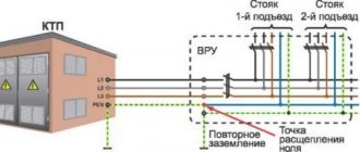
An overhead line in a village - where is the land in it?
Let's look at a regular overhead line
in an ordinary Russian village.
A SIP wire
is stretched between the poles , in which
four cores
: three phases and zero.
It turns out there is no land there? And here it is
!
Ground and zero are the same
wire - and in order to prevent the current flowing through zero from causing voltage, this wire
is grounded
at each pole.
When you enter your home
, then connect either
two
wires (220 Volts, one phase) or
four
(380 Volts, three phases).
The zero goes to your house combined with the ground
, and the “real” ground appears only in your shield, already in the house.
The shield must have two separate buses
- zero and ground. You will connect all the neutral conductors from the wiring cables to the first bus, and all the grounding conductors to the second.
Why two buses if they are connected anyway?
Main
How does grounding differ from zero in your panel - it is
never
disconnected
under any circumstances .
The zero can be torn by an automatic machine or a switch, but the earth is always “tightly” connected
to your ground loop and, through the zero on the overhead line, to the ground at the substation.
Second
the fundamental difference is that
no current flows
, except in cases where it “breaks through” somewhere and a leak begins.
This is important because if we are not grounded, but “zeroed” - to the working
zero, with current passing through it, we will not receive protection, but
danger
- getting an electric shock.
Under no circumstances should you
!
Before connecting devices to ground, make sure
what it is:
- connected in the panel to your separate ground
; - connected to zero
from the overhead line
to circuit breakers
and other switches; - connected to a separate bus
- namely the ground bus.
So your grounding is guaranteed
will perform a protection function!
Conclusion
Grounding is the basis of safe electrical engineering.
because it is it that intercepts all leakage currents that can harm you.
Take your time and find out
whether you have done it correctly. Thank you for watching!
Source: zen.yandex.ru
Residual current device (RCD) for single-phase short circuit in the cable
It is known that in case of a single-phase short circuit (SSC), the cause of which can be the melting of the insulation of the cable cores, the residual current device (RCD) does not operate, since the resulting magnetic flux when current flows between the phase and neutral conductors is zero.
In this case, the fault must be switched off by an overcurrent protection device (MCD).
However, due to the transition resistance formed by an insufficiently dense contact, a significant oxide film or charred insulation, the single-phase short circuit current flowing through the MTZ device may be less than the calculated one. As a result, the damage shutdown time of this device will increase to a value greater than permissible.
If the insulation resistance at the point of damage is less than 1000 Ohms, then the power released at the “hot spot” as a result of the flow of leakage current can reach a value of 40-100 W, which is sufficient to ignite the insulation.
To switch off damage at the early stage of a glow discharge in a network with a rated voltage of 220 V, it is proposed to use an overcurrent protection device, an RCD and a cable in which the phase conductor has a metal sheath on top of the insulation.
If during installation the metal sheath is used as a PE conductor, then the use of such a cable in conjunction with an RCD will ensure the disconnection of the short circuit in the cable when the emergency current reaches the value of the differential tripping current Idif.
In a network with Un=380 V and a TN (including TN-C) or TT grounding system, for protection against a single-phase short circuit in the cable, it is advisable to use an RCD of the VIGIREX type (TM “Schneider Electric”), whose operating current setting range is from 30 mA to 250 A. When installed, only the neutral conductor is “passed” through the RCD. The tripping current of the RCD is adjusted from the asymmetry current, third harmonic currents and harmonic currents that are multiples of the third.
In addition, as an option, for a network with a TN grounding system, a scheme is proposed with the installation of a zero-sequence current transformer (TTNP), through which all the cores of the power cable are “passed”, and the PEN (or PE and N) cable conductor is passed twice, forming a turn. A current relay is connected to the secondary winding of the TTNP, acting on the independent release or minimum voltage release of the circuit breaker, or in any other way breaking the cable power circuit.
For overhead lines, it is recommended to use three parallel-connected current transformers with a current relay connected to their secondary windings.
Unlike a circuit with an RCD, a circuit with a TTNP (or with three current transformers) in a TN grounding system operates both in case of a short circuit to the frame and in case of a short circuit between the phase and neutral conductors.
Is it possible to ground sockets to zero?
Question for experienced electricians. At the dacha, when replacing an outlet, I discovered a wire inside it running from the “zero” to the grounding contact on the same outlet; I discovered exactly the same “invention” when replacing a 5 kW instantaneous water heater - is this acceptable in the absence of proper grounding? What does this mean, how will it manifest itself in the event of a problem in the electrical network?
No you can not. There is a 3rd ground wire for this purpose. If it is not in the home wiring, then each outlet or device must be grounded. “0” is the 4th or 2nd wire in the power transmission line and is connected at the substation to the solidly grounded neutral of the transformer windings, which are connected by a “star”.
The consequences of “grounding” to “0” (or zeroing) can be disastrous. Imagine a situation when, during a thunderstorm or other phenomena and events, a phase wire breaks and falls to neutral! You already have in your house either two wires with the same phase, worse if from the neighboring one (AB, BC, CA), then this is 380! Then all the devices connected to the network will be in trouble, not to mention electrocuting people. How to make a proper grounding circuit yourself - write, I will answer.
Features of installing a grounded outlet
The connection diagram for a grounded outlet does not involve any complex manipulations. Anyone can cope with this. It is enough to familiarize yourself with the theoretical part and be careful during installation.
Before installing a grounded outlet, the type of wiring is determined. To do this, the old socket is dismantled. If two wires are connected, there is no grounding, only phase and neutral (zero phase) are available.
When purchasing a socket, the quality of the product is taken into account and preference is given to a manufacturer that has proven itself in the market. Its body must be without damage. So-called “internal” sockets are suitable for the home - they are built in when installed in a wall recess. The recommended rated breaking current for a home outlet is from 30 to 100 milliamps. Information about the rating can be read on the back of the socket. Russian samples are usually rated at 10 or 6.3A; foreign - at 10 or 16A.
Particular attention is paid to the size of the holes and the distance between them. European samples have both a larger diameter and a larger distance
If you use exclusively domestic appliances at home, it is better to buy sockets that are also domestic.
The plug can be removed from a correctly selected socket with little effort!
There is a wide variety of grounded sockets on the market:
- There are samples with overload protection - there is a built-in fuse inside, which blows out in the event of a short circuit.
- With protection against current leakage - a special device turns off the socket if a leak is detected. The socket is ideal for a child's room! As soon as the baby puts something into the socket, the protection will immediately work.
- With overvoltage protection - automatically turns off when there is a power surge, suitable for connecting expensive devices.
- With mechanical protection – special curtains protect against touching the contacts.
- With lightning protection – for regions with strong thunderstorm activity.
- For powerful devices - designed for a current of 20 amperes or more. Always sold with a special plug.
- Universal – complete with connectors for different types of plugs.
The socket box is selected based on the type of wall. The socket box is fixed inside the wall, in a special recess.
Drywall boxes are used for drywall, wood, and plastic. And for brick, concrete, foam concrete - concrete boxes. They are fixed with gypsum or alabaster mortar.
Attention! The working body of the product must be of high quality - made of ceramics. The socket contacts are made of good metal (not foil!)
It is desirable to have a screw clamp - the wires are inserted between two plates and pressed with a screw, which ensures reliable fastening of the contacts and prevents them from loosening during operation.
Poor contact at the connection point of the conductors causes an increase in current, heating the cables, which can cause an emergency situation
Therefore, it is very important to ensure the correct connection of the wires in the junction box when carrying out electrical work on a home network.
The choice of distribution boxes must be made based on their design and purpose, which is discussed in a separate article.
Before installation, turn off the power to the electrical panel. The wires are routed to the sides. The phase is determined by an electrical tester (probe). Usually the wires differ in color. Yellow-green insulation indicates grounding. If the wires are the same color, a tester will help you find the phase.
Wiring connection rules. phase - on the right, neutral - on the left, grounding - to the top or central terminal of the socket.
In practice, not everyone is lucky.
Therefore, it is easier to make a grounding loop and forget about the fact that there are jambs in your house, thanks to which you can bury someone.
Moreover, the circuit itself is not a tricky device, consisting of 3 pins one and a half meters long (you can use pipes with a diameter of 50 mm, an angle, also preferably at least 50, or fittings with a diameter of 30 mm), 3 connecting metal strips (a corner of 20 mm is possible), 1.5 - 2 meters long.
We weld a bolt (from 10-12 mm) to one of these pins and drive all three into the ground, in the shape of a triangle from each other.
Next, we connect them with a strip by welding, sprinkle them with earth and lead them into the house with wire (from 5 mm), where from it, also through the bolt using a wire (for example, ШВВГ), we bring it to the place (or socket) where we need grounding .
The work is for an hour, but the troubles, if it is not done, will last a lifetime.
I have a question: how can a phase end up on the body, is it originally on the body? All wires in electrical appliances, windings of electric motors, electric light bulbs are insulated from the housing, and in modern household appliances there is double or triple insulation from the housing. And in order for the phase to end up on the body, you just need to mechanically break the device or fill it with water. The neutral wire goes from the outlet to the substation where it is connected to the ground loop, and this neutral wire is also called the “working” wire. The ground wire goes from the outlet to the ground loop and should not be connected to the ground loop at the substation. In Soviet times, the neutral wire was often used as both a working and a protective ground at the same time, since there was no clean grounding. That’s why we now find sockets with jumpers from the ground contact to the neutral wire. In new houses they now have grounding wires, but in houses of the Soviet period there are no grounding wires. In my opinion, there is no need to install jumpers between zero and grounding, since previously there were no devices other than light and iron, but now there are a lot of household appliances and the neutral wire has lost its protective function. But grounding is not yet available everywhere. If possible, you should make your own grounding loop in dachas and private houses.
Source: www.bolshoyvopros.ru
Wire marking by color
Indeed, the easiest way to determine the phase, neutral and ground of an electrical wire is to look at the color marking and compare it with the accepted standard. Each core in modern wires used in electrical wiring and electrical equipment has an individual color. Knowing which color of cores corresponds to which function (phase, neutral or grounding), you can easily carry out further installation.
Quite often, this is quite sufficient, especially in cases where the installation is carried out in new buildings or places with fairly new electrical wiring, made by professional, competent electricians in accordance with all modern rules and standards.
According to this standard for residential electrical networks:
Working zero (neutral or zero) – Blue wire or blue-white
Protective zero (earth or grounding) – yellow-green wire
Phase – All other colors including black, white, brown, red, etc.
Now, knowing the standard for color marking of wires, you can easily determine which wire performs which function. This applies to most cases, the exception may be wires suitable for switches, switches, etc., due to the fundamentally different operating scheme of this electrical equipment.
Hazardous work practices
When grounding, you should not resort to simplified methods of this type of protection:
- using a grounding wire;
- grounding through heating system pipes.
In the first case, if all electrical appliances are working properly, the neutral conductor is ready to act as a grounding conductor.
It is worth remembering the purpose of the residual current device.
If the design is in good working order, the owner of the electrical appliance will, at best, receive a tripping of the protective element due to a short circuit. However, if the grounding wire is damaged in any way, the phase voltage (220 V) will appear on the housing.
In the second case, the pipeline system will work until part of the pipe in one of the apartments in an apartment building is replaced with plastic analogues. Due to the fall out of the metal part of the heating system, the supplied current will endanger both you and your immediate neighbors.
Under no circumstances should gas pipes be used to organize a protective grounding system. Because the electrical potential on the surface can lead to destructive consequences.
To ensure electrical safety, outlets in the house must be connected to a grounding circuit. When organizing such a protection system, you should avoid common mistakes, and entrust the installation of the circuit to an experienced electrician.
Why is this necessary?
According to the definition, grounding is the intentional connection of non-current-carrying parts of electrical equipment to the ground (equivalent), which will become energized if the wiring is damaged. In such a situation, conditions are created so that the electric current has the opportunity to go into the ground.
The action of the protective circuit is based on the difference in resistance:
- human body – at least 1000 Ohm;
- ground electrode – no more than 10 Ohms.
Thus, in the event of a current leak, touching the conductive surface of the equipment will be safe.