Hello, dear readers and guests of the Electrician's Notes website.
When carrying out electrical installation work, the question of color marking of wires is often raised.
Earlier, so to speak, in “stagnant” times, only white wires were used, less often black.
Therefore, determining phase or zero in an electrical assembly took quite a lot of time. We had to resort to voltage indicators and various analog and digital devices.
To avoid this, you need to bring the color marking of wires and buses to a single standard.
And as always, let’s turn to the regulatory documents, namely the PUE, Chapter 1, clause 1.1.29. and clause 1.1.30. It clearly states that identification of wire cores and busbars by colors or digital designations must be used in accordance with GOST R 50462-92.
According to GOST R 50462-92, clause 3.1.1, the following colors can be used to identify conductors and busbars: black, brown, red, orange, yellow, green, blue, cyan, gray, white, pink, turquoise.
According to the PUE, clause 1.1.29:
- neutral working conductors (N) must be blue
- combined neutral working and neutral protective conductors (PEN) must have blue color along the entire length and yellow-green stripes at the ends
- neutral protective conductors (PE) and protective grounding conductors must be yellow-green in color
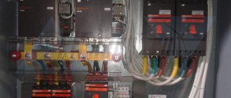
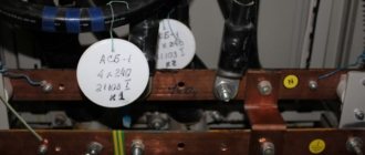
Let me give you a few photographs as an example. All neutral working conductors (N) are connected to the bus (N) and are blue. All neutral protective conductors (PE) are connected to the bus (PE) and are yellow-green in color.
And all other colors except cyan (blue) and yellow-green can be used as phase conductors.
The photographs below show that the phase conductors are white.
Color marking of wires and busbars for three-phase alternating current
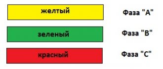
According to the PUE, clause 1.1.30, with three-phase alternating current, phase A buses should be yellow, phase B should be green, phase C should be red. It is remembered easily and simply in the form of the abbreviation “ZhZK”, i.e. yellow, green, red.
For clarity, I will give a few examples.
Busbar system with voltage 10 (kV).
Two measuring transformers NOM-10 (kV).
Outgoing feeder of a distribution substation with a voltage of 500 (V).
Outgoing feeder sections 400 (B).
As you can see, in the examples given, the color marking of buses for three-phase alternating current is fully observed.
By the way, it is not necessary that the tires be completely painted in one color or another. It is quite enough to make color markings (in the form of paint, stickers, heat-shrinkable tubes, tags, etc.) in the places where the busbars are connected to the switching devices.
Color marking of wires and busbars for single-phase alternating current
According to the PUE, clause 1.1.30, with single-phase alternating current, the phase B bus connected to the end of the power source winding should be red, and the phase A bus connected to the beginning of the power source winding should be yellow.
Unfortunately, I do not have clear examples of such electrical installations. Maybe someone has photos, I would be very grateful if you share.
By the way, if single-phase current buses are a branch from a three-phase current system, then they are designated according to the color marking requirements of a three-phase system.
Color coding of wires and busbars for direct current
According to the PUE, clause 1.1.30, with direct current, the positive bus (“plus”) should be red, the negative bus (“minus”) should be blue, and the zero operating bus (“M”) should be blue.
As an example, I will give a direct current panel (DCB) = 220 (V).
And these are the conclusions directly from the battery.
By the way, we are gradually switching from SK-5 lead-acid batteries to maintenance-free Varta batteries.
Addition
Since 01/01/2011, GOST R 50462-92, indicated at the beginning of the article, has been cancelled. Instead, GOST R 50462-2009 came into force, in which some points contradict the previous GOST. For example, clause 5.2.3 states that the following colors are preferred for phase conductors:
For clarity, I am posting a photo of the switchboard of one of the banks where we carried out electrical installations.
In my opinion, the previously adopted “ZhZK” marking is more descriptive.
In a single-phase network, the preferred color for the phase conductor is brown. Accordingly, if a single-phase network is a branch from a three-phase network, then the color of the phase conductor must match the color of the phase conductor of the three-phase network.
A ban was also introduced on yellow and green colors used separately (clause 5.2.1). They should only be used in yellow-green color combination for PE protective conductors. In this regard, the marking of the three-phase network “ZhZK” was changed, because yellow and green colors were used separately.
Read also: At what degrees does iron melt?
Digital marking of DC circuits has also been changed (clause 5.2.4):
- brown color - positive pole (+)
- gray color - negative pole (-)
- blue color - middle conductor (M)
Attention. I want to warn you that there is no need to run and change the existing marking now. After all, when the facilities were introduced, the old GOST R 50462-92 was still in effect. But when commissioning new electrical installations, GOST 50462-2009 should not be neglected.
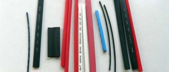
If for some reason it is not possible to mark wires and busbars according to the above requirements, then you can use any colors. But it is necessary to wrap electrical tape, stickers around the ends of the cores, put on cambrics or heat-shrinkable tubes of the appropriate color, for example, like this:
And as usual, watch the video based on this article:
The quoted requirements contain numerous errors. Firstly, the requirement of clause 1.1.30, which prescribes the use of yellow and green to identify two phase buses, should be considered a gross mistake. GOST R 50462–92, which was in force from January 1, 1994 to December 31, 2010, prohibited the use of yellow and green separately if confusion with the yellow-green color was possible. GOST R 50462–2009, which replaced it, which is valid until September 30, 2016, prohibited the use of yellow and green colors separately for identifying conductors. A similar ban is contained in the new GOST 33542 (see https://y-kharechko.livejournal.com/18503.html). The use of yellow and green colors to identify phase busbars creates conditions in low-voltage electrical installations under which it is possible to confuse protective busbars with yellow-green markings and phase busbars with yellow or green colors. At the same time, the probability of erroneous connection of protective conductors of electrical wiring to phase buses increases and, as a result, the appearance of voltage on open conductive parts of class I electrical equipment, touching which becomes fatal to humans. Secondly, busbars, which are one of the conductor options, are usually used in low-voltage switchgear, which are manufactured and certified in accordance with the requirements of national standards, which establish that the color identification of conductors must comply with the requirements of GOST R 50462–92 or GOST R 50462–2009. Thirdly, the simultaneous use of blue and cyan colors to identify the pole and middle buses will inevitably lead to dangerous confusion, since the pole bus can be under voltage of 110, 220, 440 V or more, and the middle bus is under a voltage almost equal to zero. Moreover, GOST R 50462–92 considered blue and light blue as one color. Fourthly, in the cited requirements the concepts of “ single-phase current”
" and "
three-phase current
", which is a gross error.
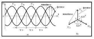
Electrical systems, electrical networks, electrical installations, electrical circuits and electrical equipment can be single-phase or three-phase. Electric current according to GOST R 52002–2003 “Electrical engineering. Terms and definitions of basic concepts" can be variable, constant, pulsating and sinusoidal. Fifthly, in the requirements under consideration, formulated for direct current electrical circuits, a zero operating bus
.
However, neutral conductors, including busbars, are used in AC electrical circuits. In DC electrical circuits, middle conductors are used. Therefore, the specified tire should be called the middle tire
.
Sixthly, phase conductors in the requirements are designated by the letters “ A, B, C
”.
However, in IEC standards and national standards developed on their basis, phase conductors are designated differently - “ L1, L2, L3
”.
Seventh, the analyzed requirements are formulated for electrical installations with voltages up to 1 kV
, and IEC standards and corresponding national standards establish requirements for
low-voltage electrical installations
operating at voltages up to 1000 V AC and up to 1500 V DC inclusive. Eighth, the requirements use outdated terminology that does not correspond to the terminology of GOST 30331.1 (see https://y-kharechko.livejournal.com/4077.html). The occurrence of errors in the requirements for color and alphanumeric identification of conductors is explained by the following reasons. Requirements of clause 1.1.29 PUE 7th ed. were formulated on the basis of the requirements of GOST R 50462–92, and the requirements of clause 1.1.30 of the PUE 7th ed. were rewritten from clause 1.1.29 of the PUE 6th ed. sample 1985. Thus, the generally accepted principles of color identification of conductors, established by the International Electrotechnical Commission and contained in the requirements of GOST R 50462–92, GOST R 50462–2009 and other national standards developed on the basis of IEC standards, have not yet received their correct reflected in the requirements of the PUE. Although the 23 years that have passed since the entry into force of GOST R 50462–92 and the GOST R 50462–2009 that replaced it were more than enough to adjust all national regulatory documentation and, moreover, the correct formulation of the analyzed requirements in Chapter 1.1 of the 7th PUE ed.
Read also: DIY gearbox lift, drawings
Conclusion.
The requirements set out in clauses 1.1.29 and 1.1.30 of the PUE 7th edition must be replaced with the following:
Color and alphanumeric identification of conductors in electrical installations should be carried out in accordance with the requirements of GOST 33542–2015
.
On the one hand, it may seem that the choice of color for the insulation of cable and wire products is carried out at the whim of the manufacturer, although this is far from the truth. Today we will fully cover the topic of marking cores both from the point of view of domestic and Western standardization, and from the point of view of practical use.
Why do we need color coding for wires and cables?
Installation and maintenance work in electrical installations is associated not only with ensuring reliability, but also safety. Complete error elimination is required. For these purposes, a system of color designations for core insulation has been developed, which determines what color the wires are phase, neutral and ground.
According to the PUE, the following colors of current-carrying conductors are allowed:
The above list contains many options for wire colors, but there are not several colors that are used only to indicate neutral and protective wires:
- blue color and its shades – working neutral wire (neutral – N);
- yellow with a green stripe – protective earth (PE);
- yellow-green insulation with blue marks at the ends of the conductors - combined (PEN) conductor.
It is allowed to use conductors with green insulation with a yellow stripe for grounding, and for combined conductors blue insulation with yellow-green marks at the ends.
The color must be the same in each circuit within one device. Branch circuits must be made with identically colored conductors. The use of insulation without differences in shades indicates a high standard of installation and greatly facilitates further maintenance and repair of equipment.
Search for phase and neutral
The work of a professional electrician always has an increased degree of danger, and especially in cases where you have to redo or repair electrical wiring that someone else has done and manually determine what color the wire is
is responsible for the phase. Sometimes a specialist is faced with a situation where the wiring in an apartment or on a panel is made with monochrome wires or without complying with color matching requirements. Then, in order to avoid the danger of receiving an electric shock, the installer has to use his knowledge and use the appropriate tool.
To manually determine where the phase is and where the zero is
or grounding conductor, an electrician can use several tried and true techniques:
- use a hand indicator or “probe”. To do this, you need to turn off the power supply, strip a pair of de-energized conductors, removing 1-2 cm of insulation from them, separate the wires and re-apply current to the electrical circuit. Carefully taking the indicator probe-screwdriver and without touching its working part, you need to touch each core by pressing the metal part (see figure) at the base of the device handle. If the “probe” lamp lights up, then this wire is phase, and the other is neutral,
- if the apartment electrical wiring is made not of a pair, but of 3 wires, then, in addition to phase and zero, you will have to determine the “ground”, which is impossible using only a manual indicator. Having found the phase conductor with a “probe”, you should use a multimeter. The device will need to set the measurement mode to 220 V, turn it on and, taking both probes in your hands, touch one of them to the phase conductor, and the other to the first of the remaining ones. Having remembered the value shown by the device, we touch the other “X” wire and remember the result. Simultaneously touching a pair of phase-zero wires with the multimeter probes will produce the standard current voltage of your household network, i.e. 220 V, and the value of the phase-ground pair will be smaller.
By the way, you can also use a multimeter to determine which of the unrecognized conductors is a phase conductor. It is necessary to set the switch to a voltage greater than 200 V and touch the conductors with a probe inserted into the “V” socket: the phase will show 8-15 V, and the neutral will leave the device needle at zero.
There are many useful videos on the Internet that allow you to visually familiarize yourself with the color marking system for wires, as well as gain practical skills on the questions “how to understand where the phase is and where the zero is” or “how to calculate the phase, neutral and grounding in the wiring for an outlet.”
Coloring phase
In cases where the electrical installation is installed using rigid metal busbars, the tires are painted with indelible paint in the following colors:
- yellow – phase A (L1);
- green – phase B(L2);
- red – phase C (L3);
- blue – zero bus;
- longitudinal or inclined stripes of yellow and green color – grounding bus.
The color of the phases must be maintained throughout the entire device, but not necessarily over the entire surface of the bus. It is allowed to mark the phase designation only at the connection points. On a painted surface, you can duplicate the color with the “ ZhZK ” symbols for paint of the corresponding colors.
If tires are not accessible for inspection or work when there is voltage on them, then they may not be painted.
The color of phase wires connected to rigid busbars may not coincide with them in color, since there is a difference in the accepted designation systems for flexible conductors and rigid stationary distribution busbars.
Neutral color
What color the neutral wire is is specified by GOST , so when looking at the installation of a power plant, the question should not arise whether the blue wire is a phase or a zero, since the blue color and its shades (blue) are accepted to indicate neutral (working grounding).
Other colors of neutral cores are not permitted.
The only acceptable use of blue and cyan insulation is to indicate the negative pole or midpoint in DC circuits. This color cannot be used anywhere else.
Ground wire color coding
The rules indicate what color the ground wire in electrical installations is. This is a yellow-green wire, the color of which stands out well against the background of the other wires. It is acceptable to use a wire with yellow insulation and a green stripe on it, or it can be green insulation with a yellow stripe. It is not allowed to use any other color of the ground wire, just as it is not allowed to use green-yellow conductors for installing circuits on which voltage is present or may be applied.
The listed labeling rules are observed in the countries of the post-Soviet space and in the countries of the European Union. Other states mark the cores in a different way, which can be seen on imported equipment.
Basic colors for marking abroad:
- neutral – white, gray or black;
- protective grounding – yellow or green.
Standards in a number of countries allow the use of bare metal without insulation as protective grounding.
Grounding wires are switched on prefabricated non-insulated terminals and connect to each other all metal parts of the structure that do not have reliable electrical contact with each other.
If colors are duplicated
The work of an electrician is subject to the requirements of GOST and PUE, while the production of cable products is not standardized in terms of color marking. For example, a cable from the remnants of a series of individual production, for example, with two brown and two blue cores, may end up on the market. What if you need to connect a three-phase power supply system using such a cable?
In such cases, you can rely on the fact that all the cores inside the common shell run strictly parallel. It is enough to establish the correspondence of at least one core at both ends of the cable, which can be done by testing relative to ground or using a pole indicator. Moreover, if on the cut on one side the remaining cores L1, L2, L3 are numbered clockwise, then on the cut on the reverse side the conventional marks will be located counterclockwise, that is, mirrored.
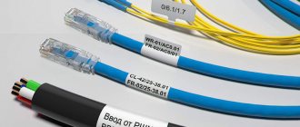
By the way, GOST allows for the absence of color markings for the so-called concentric cores, that is, located in a common shell around the circumference in one or several rows. In such cables, at least one core in each row has a color or other marking; in relation to it, the correspondence of all other cores is established in the manner described above. An example of this is a SIP without color marking, in which one of the cores has a relief strip along its entire length. This core is taken as the neutral wire, the rest are used as linear conductors. Please note that with this method of establishing correspondence between the cores, it is necessary to leave marks of different colors at their ends, for example, from pieces of heat-shrinkable tube.
Colors for 220V and 380V networks
Installation of single- and three-phase electrical networks is facilitated if the wiring is made with multi-color wire. Previously, a flat two-core white wire was used for single-phase residential wiring. During installation and repair, to eliminate errors, it was necessary to ring each core individually.
The production of cable products with colored cores in different colors reduces the labor intensity of the work. To indicate phase and zero in single-phase wiring, it is customary to use the following colors:
- red, brown or black – phase wire;
- other colors (preferably blue) – neutral wire.
The phase markings in a three-phase network are slightly different:
- red (brown) – 1 phase;
- black – 2 phase;
- gray (white) – 3 phase;
- blue (cyan) – working zero (neutral)
- yellow-green – grounding.
Domestic cable products comply with the standard for core coloring, so a multiphase cable contains differently colored cores, where the phase is white, red and black , the neutral is blue , and the ground is yellow-green conductors.
Checking that the wires are connected correctly
Any actions with cable lines should be carried out in special protection: in dielectric gloves and shoes with rubber soles. This will protect against residual voltage.
You can determine the type of wire using an indicator screwdriver. Upon contact with the phase, the neon light bulb lights up because it comes under voltage. A screwdriver with a red LED and batteries should be used to detect a broken wire.
First, turn off the electricity to prevent exposure to electric current. Next, you need to carefully unwind the insulation from the wires and separate them at a distance from each other. After this, you can turn on the power and check for phase presence.
If the wiring is made according to a two-wire circuit, then you need to find the neutral wire and the phase (the neon light comes on).
Label them in accordance with the accepted standard.0
Coloring in DC networks
For DC networks, it is customary to mark conductors connected to the positive pole in red, and to the negative pole in black or blue. In bipolar circuits, blue insulation is used to mark the midpoint (zero) of the power supply.
There are no standards for color codes on multi-voltage circuits. What color are the plus and minus wires, what voltage is in them - this can only be determined by the decoding of the device manufacturer, which is often given in the documentation or on one of the walls of the structure.
Example: computer power supply or car wiring.
Automotive wiring is characterized by the fact that in it the circuits with positive voltage of the on-board network are red or its shades (pink, orange), and those connected to ground are black. The remaining wires have a specific color, which is determined by the car manufacturer.
Letter designation of wires
Color markings can be supplemented by letters. Partially the symbols for the designation are standardized:
- L (from the word Line) – phase wire;
- N (from the word Neutral) – neutral wire;
- PE (from the combination Protective Earthing) - grounding;
- “+” – positive pole;
- “-” – negative pole;
- M – midpoint in DC circuits with bipolar power supply.
To designate the protective grounding connection terminals, a special symbol is used, which is stamped on the terminal or on the device body in the form of a sticker. The grounding symbol is the same for most countries in the world, which reduces the likelihood of confusion.
In multiphase networks, the symbols are supplemented by the serial number of the phase:
- L1 – first phase;
- L2 – second phase;
- L3 – third phase.
There is marking according to old standards, when the phases are designated by symbols and C.
A deviation from the standards is the combined phase designation system:
- La – first phase;
- Lb – second phase;
- Lc – third phase.
In complex devices, additional symbols may be found that characterize the name or number of the circuit. It is important that the markings of the conductors match throughout the entire circuit where they are involved.
Letter designations are applied with indelible, clearly visible paint on the insulation near the ends of the cores, on sections of PVC insulation or heat-shrinkable tube.
Connection terminals may have marks that indicate circuits and power polarities. Such signs are made by painting, stamping or etching, depending on the material used.
Marking of wires and cables according to the rules
Correct marking of wires and cords can greatly facilitate the installation and repair of any electrical networks. After all, correct marking will not only facilitate the installation process itself, but will also allow you or any other person to determine their purpose by simply looking at the junction box, panel or wires.
It is for these purposes that the marking of wires must be carried out in accordance with the uniform rules that are given in the “Bible” of any electrician - PUE (Electrical Installation Rules).
Rules for marking live parts according to the PUE
To ensure clarity, simplicity and ease of recognition of individual parts of the electrical network, in accordance with clause 1.1.30 of the PUE, all electrical installations must have an alphanumeric and color designation. Moreover, the presence of one of these designations does not eliminate the need for the other.
And the only relaxation is the possibility of applying a designation not along the entire length of the conductor, but only at the connection points, as shown in the video.
Wire color coding
Marking wires by color is the most visual and allows you to quickly determine the purpose of any wire. This marking can be done by selecting wires with the appropriate core insulation color, by applying paint to the busbars, or by painting or applying special colored tape at the core junctions.
Moreover, the paint on the tires may not be applied along the entire length, but only at the connection points or at the ends of the tires.
- If we talk about the color designation of wires and cables, then we should start with the phase conductors. According to clause 1.1.30 of the PUE in a three-phase network, phase conductors must be marked in yellow, green and red. This is how phases A, B and C are designated respectively.
- The instructions for a single-phase electrical network suggest the designation of the phase wire in accordance with the color of which it is a continuation. That is, if a phase conductor is connected to phase “B” of a three-phase network, then it should be green.
Note! In a single-phase network in an apartment or house, you often do not know which phase your phase wire is connected to. In order to comply with GOST, you do not have to find out this at all. It is enough to designate the phase conductor with any of the proposed colors. After all, for a single-phase lighting network, it does not matter at all which phase your conductor is connected to. The only exception is the lighting network, which uses two different phase conductors.
- As for the neutral conductors, they should be blue in color. Moreover, the color of the neutral core does not depend on the three-phase, two-phase or single-phase network in front of you. It is always indicated in blue.
- Wire markings with a yellow-green stripe indicate a protective conductor. It is connected to the housing of electrical appliances and provides safety from electric shock if the insulation of electrical equipment is damaged.
Marking of low current and signal circuits
At first glance, the colors of the wires in the control and signaling circuits are chosen arbitrarily. However, if the purpose of the conductors in a three-phase power network can be determined by a continuity signal or a phase indicator, then in a “low current” a whole series of problems arise with this. Therefore, recommendations for choosing wire markings are much more important here.
Read also: Minimum number of chain sprocket teeth
Typically, signal circuits are laid with a cable called twisted pair. This definition includes the familiar cables of local computer networks, telephone cables, and cables of industrial alarm systems. The main difference lies in the number of pairs of conductors, of which there can be up to a hundred, and the cross-section of the copper conductors. The cable is called twisted pair for the reason that all conductors in a common sheath are divided into pairs and twists among themselves. It seems that it is impossible to understand the purpose of each conductor in this “broom”.
However, everything is quite simple. The wires are actually numbered and follow a clear, color-coded sequence. If the number of pairs is more than five, they are divided into groups. In each group, the pair number from the first to the fifth is determined by the color of the solid wire: blue, orange, green, brown and gray, respectively. The group number is determined by a double-colored wire, where an additional color other than the pair number indicator indicates the group number: white, red, black, yellow, purple for groups one through five. If there are more than five groups of pairs in the cable, each five groups are wrapped with colored tape. Thus, the installer simply needs to connect the wires in series to the terminal block or cross-over block from the first pair of the first group to the fifth pair of the last group.
Also, when installing control circuits, there are several rules of good manners. For example, if you need to connect a common GND contact to an alarm device, all the green wires in the cable are used for this, that is, every third pair out of five. If it is necessary to supply constant voltage, for example, to the contacts of buttons, it is supplied through a wire with a solid color, while the corresponding “return” signal follows along a two-color wire from the same pair.
Non-standardized wire designation options
But unfortunately, the marking of the wires is phase zero; grounding is not always carried out in accordance with the PUE standards. You can often find other designations. This especially often applies to old circuits, electrical equipment, as well as some new devices from non-certified manufacturers.
And so that they do not mislead you, let's look at the most common options.
- Quite often on old Soviet diagrams you can find the symbols “F” or “F1”, “F2” and “F3”. The decoding of this designation is quite simple - it means phase. Moreover, a symbol without a letter designation is used for a single-phase network, and with a letter designation for a three-phase network.
- On the new diagrams you can find the designation “L” or, respectively, “L1”, “L2” and “L3”. This is how foreign manufacturers often designate a phase. As for digital designations, the same rule applies here - without a number for a single-phase network, with numbers for a three-phase network.
Note! For a single-phase network, the designation “F” or “L” does not indicate the importance of strictly observing the phases. That is, you can connect any phase. The same applies to a three-phase network with a digital designation. If there is a designation “Fa”, “Fv”, “Fs” or “La”, “Lv”, “Lc”, then compliance with the phase sequence is mandatory.
- The marking of wires in switchboards may contain the symbol “0” . This designation of the neutral wire is often used to this day both in diagrams and in the designation of terminals on equipment.
- To designate a protective conductor, the grounding symbol is often used, which we already discussed above . It is usually used to indicate the connection point of the protective conductor made using a system other than TN-CS.
- DC panel wire markings may contain the symbols “L+” and “L―”. These symbols indicate positive and negative conductors, respectively, and should not mislead you.
Normative base
Color marking of wires in electrical engineering is used to determine the functional purpose of a particular conductor in order to avoid erroneous switching that can lead to failure of power receivers or electric shock to a person.
The color designation of the phase, neutral and ground of the cable is not carried out at the whim of the manufacturing plants, but in accordance with GOST R 50462-2009 “Basic principles and safety principles for the human-machine interface, implementation and identification.” Identification of conductors by means of colors and alphanumeric designations”, effective from January 1, 2011.
This document replaced the outdated GOST R 50462-92, and was implemented with the aim of bringing the design of domestic power supply systems to European standards, as well as creating greater certainty in the use of color and alphanumeric designations for identifying conductors.
Next, we will try to figure out which color schemes are used for which current-carrying elements, and also talk about what to do if their markings do not comply with generally accepted standards or are completely absent.
Wire color coding
What is color coding of tires and wires and why is it needed?
Nowadays, electrical wiring is carried out using wires with different insulation colors. And the point here is not about some fashion trends or the beauty of the product itself, but about the safety and ease of use of this electrical wiring.
After all, colored insulation can perform two functions simultaneously - protection against electric shock or protection against short circuits by applying insulating material to the conductor, and with the help of the color of this very insulating material, it helps the electrician determine the purpose of this conductor.
To avoid confusion, all color colors were reduced to a single standard, described in the PUE.
Color marking can be done both along the entire length of the conductor and at the connection points of the conductors or at their ends. To do this, colored electrical tape or heat-shrinkable tubes (cambrics) can be used.
In this article we will look at color marking in single-phase and three-phase circuits, as well as in DC circuits.
The need for marking phase wires
Color marking of conductors in a cable product is also necessary so that when installing/repairing electrical networks or equipment, you know exactly the purpose of each core. In this case, all operations for connecting them to the load are significantly simplified and accelerated. At the same time, the likelihood of technological errors associated with incorrect connection of phases to the electrical installation is reduced.
The color marker of power conductors is mandatory for electrical networks preparing for commissioning. It is strictly regulated by current regulatory documents, including PUE and a number of GOSTs. The latter include GOST R 50462 of 1992, in paragraph 3.1.1 of which it is noted what colors of insulation and tire painting are allowed to be used. The correspondence of colors and letter designations for each phase is determined by GOST 28763 of 1990.
In the absence of such marking, no inspection commission will allow a newly introduced or restored electrical network to operate. When using conductors with the same insulation, it is allowed to mark them with special cambrics of the corresponding color, placed on the ends of the mounted core.
Wire colors in a single-phase network
Different colors of wire insulation become most relevant when the installation of electrical wiring is carried out by one person, and repairs and maintenance are carried out by another. The main purpose of color marking is to make it easy and quick to determine the purpose of any of the wires.
Phase wire colors
According to the PUE, phase wires in a single-phase electrical network can have the following insulation color - black, red, brown, gray, purple, pink, orange, white, turquoise. This color marking is quite convenient - when you see a wire with this color of insulation, it becomes clear that you have a phase in front of you (but it is still better to double-check, since in practice there are cases when the marking is not observed).
Zero working conductor or neutral
The neutral or neutral working conductor (N) is usually made with a wire with blue insulation.
Neutral protective conductor and neutral combined conductor
The neutral protective conductor (PE) has a yellow-green insulation color. The combined neutral and working conductor (PEN) has a blue color with yellow-green marks at the end, or vice versa - a yellow-green color with blue marks at the end.
If you do not have a wire of a suitable color, then installation can be done with a wire of any color (except for the protective PE conductor that is colored) by marking the ends of this wire with colored electrical tape or heat-shrink tubing, which have a color indicating the purpose of the conductor. You can also mark the ends of the conductor with the desired color in the case when the installation has already been carried out with a conductor of a different color.
Below are the colors that indicate phase, neutral, protective and combined conductors:
Single-phase two-wire network 220V
This type of network includes an outdated type of wiring, where aluminum wires in a single white braid, popularly known as “noodles,” are used as cores. One core of the electrical wire is a phase conductor, the second core is a neutral conductor. A single-phase two-wire network is used for ordinary household needs: simple sockets and switches.
We talked about how to properly arrange an in-house electrical network in this article.
The problem when installing single-color wiring is that it is difficult to determine the phase and neutral wires. The presence of additional measuring equipment will help to cope with the task; you can use a multimeter or a special screwdriver with an indicator, a probe, a tester, or a “continuity tester”.
Colors of wires and buses in the AC network for a three-phase connection
To maintain the correct phase rotation when connecting three-phase consumers of electrical energy, color marking of buses and cables is also used. This makes life much easier for installers and repairmen, since by the color of the cable or bus, you can determine the phase that is connected or will be connected to this cable or bus. Unlike single-phase consumers, where the phase wire can be made of cables with different insulation colors (list above), for three-phase consumers the colors that can be used to indicate phases are strictly regulated by the PUE.
For a three-phase connection, phase A should be indicated in yellow, phase B in green, phase C in red. Zero working, protective and combined conductors have the same color as with a single-phase connection.
It is permissible to color code cables and buses not along their entire length, but only at the points where cables or buses are connected, as shown in the figure above.
Also, color codes may comply with the international standard IEC 60446 or may use the coding adopted within the country by the relevant regulatory documents. For example, in the USA and Canada, different color codes are used for grounded and ungrounded systems. Below is a table showing the color coding of cables and busbars in different countries for comparison:
Three-phase network 380V
A three-phase network, just like a single-phase one, can be with or without grounding. Depending on this, a three-phase four-wire electrical network with a voltage of 380V and a three-phase five-wire network are divided.
A four-wire network consists of three phase conductors and one neutral working conductor; there is no protective grounding conductor here. In a five-wire network, in addition to three phase conductors and one neutral, there is also a grounding conductor.
Color codes for wires in a three-phase 380V network
Colors of wires and buses in DC circuits
DC circuits typically use only two buses, namely plus and minus. But sometimes DC circuits have a middle conductor. According to the PUE, buses and wires are subject to the following markings in DC circuits: positive bus (+) - red, negative (-) - blue, zero operating M (if available) - blue.
Wire insulation colors plus and minus
The color markings of DC and AC electrical networks are different. In the first, the current flows only in one direction, so a different connection diagram is used.
If in an alternating network a closed circuit is necessary for the flow of current, then for a direct current there is no need for it. The movement occurs from plus to minus.
Polarity is indicated by 2 colors: positive is red, and negative is blue or black.
Since when using multi-group circuits in DC devices it is impossible to know exactly which wire is positive and which is negative, it is necessary to review the accompanying technical documentation. Some circuits use a neutral wire, marked blue.