Accidents may occur in electrical networks from time to time. Moreover, accidents happen regardless of how long ago the lines were installed.
This can lead to voltage surges, phase imbalances, and changes in voltage levels that become either too low or too low in the electrical network.
There are different ways to deal with such problems. One of the most effective ways is to include a voltage release for the maximum and minimum levels in the electrical network.
We will consider one of these releases in our article, namely RMM 47. Read about the operation of this device and technical parameters further in the article.
More about the release
As you can understand, RMM‑47 is a model of overvoltage and undervoltage release. Such devices are installed together with load switches and circuit breakers.
The width of this device is a little more than fifteen millimeters; in the shield this element occupies one module.
The key parameter of the device is its response fault. The device will operate at a minimum voltage of 165V and a maximum voltage of 265V. The deviation from the set value can be an error of ten percent.
The response threshold of this device cannot be adjusted. The maximum possibility of control is to release the triggering mechanism and return the device to its original state after triggering.
Stages of operation of the protective valve
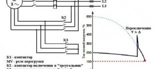
In practice, two-stage protection systems are used. This operating algorithm makes it possible to differentiate the response of the cervical nerve depending on the voltage. Let's consider the operation of actuation degrees.
1st stage.
This protection stage is activated at a voltage of 70% of the rated value (Unom), the response time delay is set in the range of 0.5-1.5 seconds, which corresponds to the parameters of the current cut-off current. When the 1st stage of protection is triggered, non-essential equipment is switched off.
2nd stage.
It operates when the voltage drops to 50% of the nominal value. Under such conditions, autostart of electric motors is impossible. The activation delay of the 2nd stage is set in the range of 10.0-15.0 seconds, after which the critical engines are turned off. This time is set to allow the automation to connect a backup power source or reduce operating currents by turning off non-critical equipment.
Why is a release needed?
Devices like PMM 47 are used for installation in electrical circuits to protect devices from over or undervoltage levels. A change in voltage level occurs for the following reasons:
- The network burns out zero.
- There was a phase imbalance in the three-phase network.
Note that RMM 47 will not protect the electrical network from pulses with a large number of volts. The device itself monitors the characteristics of the electrical network and, registering deviations, de-energizes energy consumers.
To protect the power grid from large pulse surges, you need to use other network protection elements. A surge voltage protection device based on a varistor is suitable.
Minimum and maximum voltage releases can be connected to the input circuit breaker, protecting the network of the entire facility, or individual power consumption devices can be protected.
Purpose
MVP (minimum voltage protection) is used in conjunction with protections that monitor the network. Operated in conjunction with an automatic transfer switch (ATS) device. The ZMN performs a shutdown or sends an appropriate signal to the user (system) when an emergency occurs in the consumer network, as a result of:
- Short circuit when significant power loss occurs. Large currents arise and the voltage drops sharply.
- Network congestion. (The power supply is insufficient or one of them has failed).
This action ensures the safety of important mechanisms during self-starting, when inrush currents cause a decrease in voltage. Automation turns off the operation of less important mechanisms.
Device installation
If the voltage relay has power contacts, then the RMM 47 does not have such contacts. For this reason, you will not find the rated current value in the parameters. Essentially, a release is an additional device for circuit breakers and load switches.
Usually you can find a small hole on the side of the machine body. It is through this hole that you can connect additional elements to protect the network.
By turning the plug automatically and freeing up some space in the case, you will find a place for connection.
Here you can also see a piece of the machine gun cocking mechanism. The left side of the trip unit has a small pin that can be used to connect the device to the circuit breaker for joint operation and complete safety.
In general, from this we can draw a conclusion about how this device works.
- The board inside the device analyzes the current voltage levels in the network. It is thanks to the board that the rated voltage values and possible deviations are compared.
- If the device detects strong deviations, it sends a signal that communicates with the machine. Because of this, the circuit breaker reacts to changes in the network.
- So, the network was cut off from the power supply. To return the network to its previous state, you need to re-enable the corresponding buttons on the security devices.
The RMM-47 release from EKF burned out
I have a question about connecting the RMM-47 release. It has two contacts, there is a diagram for it
But on the device itself, this diagram does not contain information about the numbering of the terminals.
So, it is not clear whether it is important for him to which terminal to apply the phase to, and to which zero? There is no marking on the device itself which terminal is which. The EKF device burned out after applying voltage.
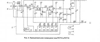
The device consists of an electronic threshold element on two transistors, there is a bridge at the input and the mechanics are controlled using an electromagnet. One of the transistors and the electromagnet burned out completely.
It doesn’t matter where you submit what, you yourself write that there is a diode bridge at the input. As far as I understand, it burned out after the first turn on. How many volts were supplied?
The apartment network is 220V, I plugged it into the apartment panel, connected these two terminals to the input line (the one that comes from the meter) and turned on the electricity in the common panel, it burned out immediately.
Maybe it is designed to be turned on after a controlled machine? those. so that it is de-energized immediately after the machine is triggered
Then, perhaps, he would have managed to de-energize himself without dying))
hommar wrote: maybe it is designed to be turned on after a controlled machine?
It does not control the machine, but the voltage. And, apparently, he was dead even before connecting to the network.
It also seems to me that marriage, because... After disassembling, an incomprehensible twist (.) was discovered on the coil. I'll try to install the IEC.
But I wonder if it will somehow automatically protect itself or not? (except entrance)
Well, in the general panel it costs 40A automatic. And I install the RMM in the apartment between the meter and my machine. As far as I understand, this is correct
realsystem wrote: And I install the RMM in the apartment between the meter and my machine
It’s not clear how you installed it. The relay should be mechanically connected to the machine and act on it when the voltage increases or decreases. 220 Volts are supplied to it. And as I understand, you sent the current of the entire apartment through it.
realsystem wrote: connected these two terminals to the input line (the one that comes from the meter)
Am I mistaken or should it still be mechanically connected to AB? What's the point of just connecting it?
greg111 wrote: am I mistaken or should it still be mechanically connected to the AB?
Here you can see and read how it should connect. " >
2amidant yes I am aware of that. I thought that the TS was not quite.
I connected it mechanically to the machine, everything is clear. But I electrically connected the two terminals of the device with phase and zero, i.e. parallel to the machine. Judging by the link, my mistake was that I connected the device before the machine, but in the diagram after the machine. But I don’t understand how this affected the combustion.
realsystem wrote: Judging by the link, my mistake was that I connected the device before the machine, but in the diagram after the machine. But I don’t understand how this affected the combustion.
There was an error in the circuit design, but this could not affect the “quality” of Chinese products in any way.
realsystem wrote: But I don’t understand how this affected the combustion.
This means it’s a defect and you can try to return it to the store. I think that if you take the same crap and not money, then there should be fewer problems.
amidant Yes, I already disassembled it by drilling out the rivets, but I’m too lazy to download the right ones, they will say that I connected it incorrectly - and that’s why it burned out. They're stupid salesmen.
realsystem wrote: These sellers are stupid.
I think that it is not the sellers who should deal with your case.
I’ll send it to the factory and write them a ton of letters.
I’ll tell you if you don’t understand it, I’ll do active anti-advertising
realsystem wrote: I’ll say if you don’t understand, I’ll do active anti-advertising
There is no other way, either let it be according to the STD, or so
When buying low-quality products, be prepared to suffer all the consequences of *quality*.
I plugged this one into the network directly, after 5 seconds smoke began to appear and it burned out.
hommar wrote: maybe it is designed to be turned on after a controlled machine? those. so that it is de-energized immediately after the machine is triggered
Then, perhaps, he would have managed to de-energize himself without dying))
That's right, put it this way.
I would like to join the claims of realsystem EKF. I have a similar situation: I connected RMM-47 to protect equipment powered by single-pole VA 16A and 6A (I powered RMM-47 to these VA, but there was an AD-32 32A in front of them, i.e. RMM-47 could physically turn off VA 16A and 6A, and power for RMM-47 and VA 16 A and 6A was supplied from AD-32 32A). A few months after the normal operation of the 3-phase switchboard in which it was located, at night, these RMM-47s suddenly clicked and there was a smell of burning. Having turned off the entire shield with the counter, I began to find out what was going on with a flashlight. Both RMM-47s heated up, turning off both VAs (only the RMM-47s smelled like burning). After waiting for the RMMs to cool down, I turned them on and both VAs after 30 minutes - they didn’t work anymore - and decided that everything was working in the same normal mode, because... The RMM-47 return button was pressed normally. A few months later I decided to add RMM-47 EKF to the same 3-phase shield to protect other VAs. It’s good that the “7th sense” worked - let me, I think, I’ll check on the LATR with a multimeter how these new external design ones (the old RMMs were “square”, and the new ones are more rounded in the front) work, at what voltages? It’s a pity that I didn’t check the old RMMs before installation. Having connected new RMMs after LATR in parallel with the multimeter, I set 185 V (LATR did not allow less) - the RMM did not turn off. Then I smoothly increased the voltage to 250 V and the RMM worked, starting to smoke at the same second. Having opened this burnt RMM-47 EKF (new design), I saw a handkerchief with an exploded thyristor BT169D and a varistor (I assume), a jammed solenoid, which should mechanically apply force to the plastic lever, and that, in turn, turn off the VA. The coil in this solenoid is charred and heats up the plastic base on which it is wound, and in this base a metal pin must move to apply force to the lever. After such a test of the new RMM-47 EKF, purchased for 500 rubles, I decided to remove and also open those old RMM-47 EKF that had previously worked for me (those that I could remove, I removed, those that I could not, I de-energized). I saw that there was the same jammed solenoid, but several resistors were blackened. So, I think, a reasonable question for EKF: why does the RMM-47 EKF device, which should turn off VA at 170V +/-5% and 270V +/-5%, already at 250V BECOME FAULTY. Where does it say that this is a disposable device? Why is it not written after the VA WITH WHAT overload response current this RMM-47 EKF should be installed (I mean what VA the RMM-47 itself should protect). realsystem, what successes have you achieved regarding claims against EKF or sellers of RMM-47 EKF? I repeat that I want to support you in this difficult matter.
Installation and connection diagrams for the release
The device is connected to the phase. The phase comes out of the machine, and it is important to remember that RMM 47 and the automatic switch are connected to each other.
This installation method is as follows: when connected from a phase to a circuit breaker, the devices will be protected, but the coil may break. This has been proven by numerous expert tests.
If voltage level deviations are found, the release must also be de-energized. To do this, you need to properly connect the element to the network so as not to buy a new device in the future.
For proper connection, use the diagrams that we demonstrated in our article.
Release RMM47 from IEK
Hello dear reader. The only people who haven’t heard about “voltage surges” in our country are those happy people who chose to live in the taiga in the cold, in harmony with nature, far from the benefits of civilization. In the harsh techno-reality, the multi-apartment mess, optimized by effective managers from the housing and communal services sector, is successfully growing stronger, and the frightened to death average person is buying up voltage relays en masse.
And these relays, in general, work. Sometimes with glitches, sometimes with failures, but they work.
But what does the Holy Book say about protection against overvoltage? Here's what:
When supplying single-phase consumers from a multiphase supply network..... it is recommended to provide protective shutdown of consumers when the voltage exceeds the permissible..... . The disconnection must be carried out ..... by influencing the independent release of the input circuit breaker using a maximum voltage relay, and both the phase (L) and neutral working (N) conductors must be disconnected.”
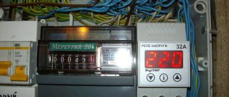
And then, recently, in one of the Yaroslavl new buildings, I met something beautiful:
The leftmost device in this row is the C40 two-terminal input device. And to the right of it (and connected to it) is the minimum/maximum voltage release RMM47.
The operating algorithm of this device is simple. The release monitors the network voltage and when it goes beyond the permissible limits (165+/-10…265+/-10V) it triggers the circuit breaker to which it is connected. At the same time, the “Return” button protrudes from the body so that it is visually clear why the machine worked - due to overload/short circuit or due to voltage problems.
Simple, reliable, cheap. The only drawback is that the release cannot reset the machine, that is, it does not have an automatic reclosure function. However, the Rules do not require this.
Of course, not only IEK, but also other manufacturers have such devices. True, not everyone combines both functions in one device - protection from both overvoltage and undervoltage. Yes, and there are nuances in connection diagrams. The operation of the most accessible releases on the Russian market can be seen in a wonderful video filmed by my fellow countryman and colleague Alexey. Thanks to him.
And here, when it would be very convenient to end the article on this positive note, someone will certainly say: “What about the sausage?” Yes, dear reader, the lack of an automatic reclosure function in releases periodically leads to heated debates on the topic “Tripper vs. Sausages” or “Sausage vs. Releaser.” Indeed, if you are away from home for a long time, and the circuit breaker “drops” the machine during this time, then upon arrival, the first thing you will have to do is throw out the refrigerator, without opening it. If a voltage relay is used instead of a release, such a problem will not happen. But this can happen:
Taken from here.
Or this:
And this is from here.
Let's draw the line
Since RMM 47 is a standard model, its analogues are produced by different manufacturers. Among them are companies such as:
- Russian.
- Another domestic one.
- A large company producing electrical equipment "TDM".
These devices are not mandatory items in electrical networks, but they are recommended for installation for greater network security. If you are worried about power consumption devices, it is better to choose a voltage relay for installation.
The relays will help determine the boundaries of the required registration of voltage deviations in the network and the response thresholds. Thanks to this, the device can be adjusted to the network characteristics, which are always individual.
However, the inability to adjust the response threshold values is not a disadvantage for everyone: for some it is a plus, since the device does not require much knowledge of its operation.
These are the main points on the operation of the PMM 47 release. Now that you are familiar with the operation of the device, you can decide whether such a device is needed in your electrical network.
Application
Despite some disadvantages, undervoltage protection is closely related to production processes and ensures reliable operation of technical equipment.
It is used to provide protection at power plants, ensuring the operation of important mechanisms in the event of a short-term loss of its own power. It is installed in problem areas of the power grid and substations, first disconnecting consumers of the third category. Ensures that voltage is maintained at vital facilities (hospitals, railways, communications, water supply, sewerage).
Varieties of the model range
Many home craftsmen prefer to use time-tested independent releases. Such units operate solely under the influence of voltage, which gradually passes through the main circuit of the circuit breaker. The great popularity of such installations arose against the background of the fact that each master can control the system remotely, which is not provided for in other categories of releases.
An automated switch helps to timely disconnect from the power supply absolutely all devices and other sources that operate using electricity. This function is especially important in situations where there is a noticeable voltage deviation in the network from the norm specified by the consumer
But it is important to take into account the disadvantages that are associated with the conversion of energy into heat release. The presence of such a factor may result in the switch being disconnected improperly
Modern Z-ASA/230
Manufacturers note the fact that turning off ventilation in the event of a fire through an independent switch of this series occurs extremely quickly. This model comes with high quality moving modules and six pairs of contacts. This device is especially relevant for impulse switches. The unit works great in extreme conditions where there is high humidity. The device is often used by specialists for remote control. The level of current conductivity is equal to 4.5 microns.
Improved modifications for 30A
This type of release for a circuit breaker is manufactured with a special code expander. The final output voltage is equal to 35 V. The smooth operation of the unit is associated with diode rectifiers. All contacts are mounted on movable plates.
Experts have provided for the presence of transceivers with trimming resistors. Many models in this category are connected to electrical panels via high-quality capacitor units. To prevent the negative impact of unscheduled overloads on the network, expansion dinistors are used.
Unit IEK РН47
Experts confidently claim that this release is one of the most popular. The compactness of this model is of great importance. Reliable fixation with the shield is ensured thanks to small capacitor units. In addition, the model has only two rectifiers, and all contacts are movable.
The expander itself is located in the lower compartment of the structure along with the relay. The presence of a transceiver is not provided.
Particular attention should be paid to the operating parameters of the independent release - the output voltage is within 40 V. The maximum network load should not exceed 30 A
In addition, manufacturers have conducted numerous studies that have shown that the minimum trip temperature is within -10˚C. The unit is not at all afraid of exposure to high humidity. All wiring is insulated in a special way for safe operation of the device.
Household SHUNT 250 VAC
This model of independent release is produced on the basis of a diode rectifier, which is located above the relay
Attention should also be paid to the operating parameters of the system, which are 44 ohms. Standard threshold overload is equal to 24 A
A miniature capacitor unit is used to connect the modification.
All conductors are equipped with powerful insulators. The unit is equipped with three pairs of resistors, securely fixed above the rectifier. Manufacturers did not provide for the presence of a stabilizer. This makes this model ideal for low-power drives.