05/08/2020 632 Generators
Author:Ivan
Depending on the device and operating principle, generator voltage relay regulators in a car are divided into several types: built-in, external, three-level and others. Theoretically, such a device can be made independently; the simplest and cheapest option in terms of implementation is to use a shunt device.
[Hide]
Basic automatic control processes
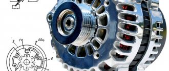
It doesn't matter what type of generator set is used in the car. In any case, it has a regulator in its design. The automatic voltage regulation system allows you to maintain a certain parameter value, regardless of the frequency at which the generator rotor rotates. The figure shows the generator voltage regulator relay, its diagram and appearance.
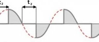
By analyzing the physics by which a generator set operates, it can be concluded that the output voltage increases as the rotor speed becomes higher. It can also be concluded that voltage regulation is carried out by reducing the current supplied to the rotor winding as the rotation speed increases.
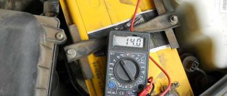
Additional regulator for car generator
Charging the battery in a car from a standard generator, especially in the winter, can cause some difficulties. Due to the operating error of the built-in voltage regulator, the current supplied to the excitation winding of the generator is insufficient to maintain the output voltage at 14.2...14.7 V, even without connecting consumers. Connecting a load, namely low beam lamps and various types of heaters, only aggravates the situation. Constant undercharging threatens the formation of lead sulfate on the battery plates, which reduces its capacity and, ultimately, not only prevents the engine from starting, but also damages the battery. For example, in its instructions it states: “For efficient and complete charging of batteries manufactured using Ca/Ca technology, the charger must provide a charging voltage of 16.0 V.” For an on-board network, this voltage is too high, but for charging in winter during trips, 14.5...14.8V is enough. A very popular solution to this problem on the Internet is to connect a diode in series to the power supply gap of the car generator voltage regulator. The essence of the improvement is as follows. The built-in generator regulator monitors the vehicle's electrical supply voltage. Adding a diode subtracts 0.5...0.7V from its supply voltage, depending on its type and load current. The regulator will strive to compensate for this voltage drop, since the supply voltage in the network has decreased, the current in the excitation winding of the generator will be increased to a value that will add exactly this value of the voltage drop, which will lead to an increase in the voltage of the on-board network. The method is simple and effective. But there is a drawback - due to the specific type of diode, load current and ambient temperature, the voltage drop may differ significantly from the required one. The proposed design will help to introduce predictability into the operation of a car generator by adding an adjustable voltage boost - connecting the proposed device between the power supply of the standard built-in car generator and the power supply of the car's on-board network.
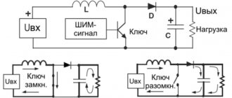
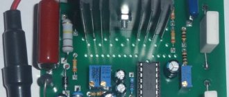
The scheme is quite simple:
The basis of the circuit is op-amp DA2. It compares the reference voltage coming from elements C1, R1...R3, DA1 with the voltage taken from the drain of transistor VT1. A decrease in the drain-source voltage drop of VT1 relative to the reference voltage leads to its closing, which stabilizes the subtractive voltage of the generator regulator at the level set by resistor R3. Elements R4, R5, C2 prevent self-excitation of the circuit; op-amp DA2 without them on the capacitive load, which is the gate VT1, will not work normally. Capacitors C1, C3…C5 filter noise in the power supply circuit. Diode bridge VD1 - emergency. In case of abnormal operation of the regulator, it will not allow the voltage drop in the supply circuit of the voltage regulator to exceed 1.4V. Resistor R6 is necessary for the initial adjustment of the voltage drop between the drain-source terminals of transistor VT1 without connecting to the generator.
Photo of the assembled device:
Elements C1, C4, C5, DA1, R3 are glued to the board. This will help them survive vibration while the car is moving. The soldering side of the PCB components is coated with acrylic varnish to protect it from moisture:
The board itself is installed on the radiator:
Actually, a more modest radiator would suffice, an aluminum plate 5mm thick would suffice, but whoever has what is available. The external components are also partially coated with acrylic varnish. The entire assembly is housed in a suitably sized housing:
It also has a regulator switch for operation in the warm season:
In this case, it closes the input and output circuits (drain - source of transistor VT1), eliminating the influence of the device on the operation of the generator.
The regulator, assembled from serviceable elements, does not require additional settings. Adding the required voltage to the vehicle's electrical system is carried out by adjusting resistor R3. This value is monitored using a voltmeter between the input and output circuits of the regulator (drain - source of transistor VT1).
About replacing elements. Any op-amp DA2 is suitable, allowing operation at input voltages equal to the supply voltage; the datasheet indicates “common-Mode Input Voltage Range Includes VCC+”. Of the least exotic ones, LF355/6/7 op-amps are suitable. Here it is necessary to add that the use of a collet socket for an op-amp is a necessary measure. What was sold under the label TL071CN did not correspond to reality - they did not operate from input voltages equal to the supply voltage. I had to pick it up. If there are no problems with the original op-amps, it is better to solder the chip directly to the board. Transistor VT1 can be replaced with IRF5210N or similar. However, we should not forget that the drain-source resistance of the transistor used limits the minimum voltage drop across the regulator, and therefore the minimum voltage increase in the on-board network. In other words, transistors with a high drain-source resistance will work like regular resistances even when an opening voltage of 15V is applied to the gate-source. Any diode bridge VD1 is suitable for convenient installation on a radiator with a “screw”. In general, this is precisely the reason for choosing the diode bridge.
It would be possible to use 2 diodes connected in series, but they are more difficult to attach to the radiator. It is also worth noting that if the voltage boost does not exceed 0.6V, you can limit yourself to only one protective diode. In the case of using a diode bridge, you can connect the “~ ~” pins with “+” or “-” on the board with a jumper. The task of DA1 is to maintain a stable reference voltage regardless of the ambient temperature. The reference voltage source DA1 can be replaced with a low-voltage zener diode or stabistor. In this case, you may have to change the values of resistances R2, R3 for smooth adjustment. As a last resort, instead of DA1, you can use 3 series-connected 1N4148 diodes - this will work, but the error will be +-6.3 mV per change of one degree Celsius. If you adjust the voltage drop of the regulator “in cold weather” (with resistor R3), this may turn out to be acceptable due to relatively small temperature fluctuations.
To simplify installation in the car hood, it makes sense to provide connection terminals:
And the most important thing. For this modification of the generator, it is necessary that the built-in regulator of the automobile (or tractor) generator has a separate power supply. For example, from the ignition switch. In this case, the connection will not cause any difficulties. In contrast to design solutions, where the built-in regulator is powered from the internal circuits of the generator. In this case, you cannot do without partial disassembly of the case...
List of radioelements
| Designation | Type | Denomination | Quantity | Note | Shop | My notepad |
| C1 | Electrolytic capacitor | 10 µF | 1 | Search in the Otron store | To notepad | |
| C2, C3 | Capacitor | 1 µF | 2 | Search in the Otron store | To notepad | |
| C4, C5 | Electrolytic capacitor | 220 µFx25V | 2 | Search in the Otron store | To notepad | |
| DA1 | Voltage reference IC | LM385-2.5-N | 1 | Search in the Otron store | To notepad | |
| DA2 | Operational amplifier | TL071 | 1 | Search in the Otron store | To notepad | |
| R1 | Resistor | 1.8 kOhm | 1 | Search in the Otron store | To notepad | |
| R2 | Resistor | 13 kOhm | 1 | Search in the Otron store | To notepad | |
| R3 | Trimmer resistor | 20 kOhm | 1 | Search in the Otron store | To notepad | |
| R4 | Resistor | 20 kOhm | 1 | Search in the Otron store | To notepad | |
| R5 | Resistor | 100 Ohm | 1 | Search in the Otron store | To notepad | |
| R6 | Resistor | 1.5 kOhm 0.5 W | 1 | Search in the Otron store | To notepad | |
| VD1 | Diode bridge | GBU10005 | 1 | Search in the Otron store | To notepad | |
| VT1 | MOSFET transistor | IRF4905 | 1 | Search in the Otron store | To notepad | |
| Add all | ||||||
Attached files:
- Polzovatelyam.zip (73 Kb)
What is a generator
Any car generator consists of several parts:
1. A rotor with an excitation winding, around which an electromagnetic field is created during operation.
2. A stator with three windings connected in a star configuration (alternating voltage is removed from them in the range from 12 to 30 Volts).
3. In addition, the design contains a three-phase rectifier consisting of six semiconductor diodes. It is worth noting that the VAZ 2107 generator voltage relay-regulator (injector or carburetor in the injection system) is the same.
But the generator will not be able to operate without a voltage regulation device. The reason for this is the voltage change over a very wide range. Therefore, it is necessary to use an automatic control system. It consists of a comparison device, control, executive, master and special sensor. The main element is the regulatory body. It can be either electrical or mechanical.
Which is better: stabilizer vs relay
Often, instead of connecting a control relay in the panel, electricians recommend installing a voltage stabilizer in the house. In some cases this may be justified. However, there are a number of nuances that must be remembered when choosing one or another option for protecting electrical appliances.
In terms of functionality, the stabilizer not only equalizes the voltage, but also turns off when the voltage is too high. A voltage relay is an exclusively protective automatic device. It seems that the first includes the functions of the second.
But compared to the RKN stabilizer:
- more expensive and noisy;
- more inert during sudden changes;
- does not have the ability to adjust parameters;
- takes up much more space.
When the input voltage is reduced so that the output of the stabilizer has the required indicators, it begins to “draw” more current from the network. And this is a direct path to wiring burnout if it was not originally designed for this.
The second main disadvantage of the stabilizer in comparison with the control relay is its inability to intercept a sharp voltage surge when the zero is broken.
Literally half a second with 350-380 W in the outlet is enough for all the equipment in the house to burn out. But most stabilizers are not able to adapt to such changes and pass high voltage, turning off only 1-2 seconds after the start of the surge.
In addition to stabilizers and relays, overvoltage and undervoltage releases can also be used to protect the line from voltage surges in the network. But they have a longer response time compared to the RLV. Plus, they do not turn the power back on automatically; their operation is more like an RCD.
After a power outage, these releases will have to be reset manually.
Generator operation
When the rotor begins to rotate, some voltage appears at the generator output. And it is supplied to the excitation winding through a control element. It is also worth noting that the generator set output is connected directly to the battery. Therefore, voltage is constantly present on the excitation winding. When the rotor speed increases, the voltage at the generator set output begins to change. A voltage regulator relay from a Valeo generator or any other manufacturer is connected to the generator output.
In this case, the sensor detects the change, sends a signal to a comparing device, which analyzes it, comparing it with a given parameter. Next, the signal goes to the control device, from which it is supplied to the actuator. The regulatory body is able to reduce the value of the current that flows to the rotor winding. As a result, the voltage at the generator set output is reduced. In a similar way, the mentioned parameter is increased in the event of a decrease in rotor speed.
Purpose of the voltage regulator relay on the VAZ 2106
As you know, the power supply system of the VAZ 2106 consists of two important elements: a battery and an alternator. A diode bridge is built into the generator, which motorists in the old fashioned way call a rectifier block. Its job is to convert alternating current into direct current. And to ensure that the voltage of this current is stable, does not depend on the rotation speed of the generator and does not “float” much, a device called a generator voltage relay regulator is used.
The internal voltage regulator of the VAZ 2106 is reliable and compact
This device provides constant voltage throughout the entire on-board network of the VAZ 2106. If there is no relay regulator, the voltage will deviate abruptly from the average value of 12 volts, and it can “float” in a very wide range - from 9 to 32 volts. And since all energy consumers on board the VAZ 2106 are designed to operate under a voltage of 12 volts, without proper regulation of the supply voltage they will simply burn out.
Design of the relay regulator
On the very first VAZ 2106, contact regulators were installed. It is almost impossible to see such a device today, since it is hopelessly outdated, and it has been replaced by an electronic regulator. But to get acquainted with this device, we will have to consider the contact external regulator, since its example reveals the design most fully.
The first external regulators of the VAZ 2106 were semiconductor and were implemented on a single board
So, the main element of such a regulator is a winding of brass wire (about 1200 turns) with a copper core inside. The resistance of this winding is constant and is 16 Ohms. In addition, the regulator design includes a system of tungsten contacts, an adjustment plate and a magnetic shunt. There is also a system of resistors, the connection method of which can change depending on the required voltage. The highest resistance these resistors can provide is 75 ohms. This entire system is housed in a rectangular PCB body with contact pads for connecting wiring brought out.
Operating principle of the relay regulator
When the driver starts the VAZ 2106 engine, not only the crankshaft in the engine begins to rotate, but also the rotor in the generator. If the rotation speed of the rotor and crankshaft does not exceed 2 thousand revolutions per minute, then the voltage at the generator outputs does not exceed 13 volts. The regulator does not turn on at this voltage, and the current goes directly to the excitation winding. But if the speed of rotation of the crankshaft and rotor increases, the regulator automatically turns on.
The relay regulator is connected to the generator brushes and to the ignition switch
The winding, which is connected to the generator brushes, instantly reacts to an increase in crankshaft speed and is magnetized. The core located in it is pulled inward, after which the contacts on some internal resistors are opened, and the contacts are closed on others. For example, when the engine is running at low speeds, only one resistor is used in the regulator. When the engine reaches maximum speed, three resistors are turned on, and the voltage on the excitation winding drops sharply.
Two-level regulators
A two-level automatic control system consists of a generator, a rectifier element, and a battery. It is based on an electric magnet, its winding is connected to the sensor. The driving devices in these types of mechanisms are very simple. These are ordinary springs. A small lever is used as a comparison device. It is mobile and makes switching. The actuator is the contact group. The control element is a constant resistance. Such a generator voltage regulator relay, the diagram of which is given in the article, is very often used in technology, although it is morally outdated.
ILV connection diagrams
In the panel, the voltage relay is always installed after the meter in the break of the phase wire. He must control and, if necessary, cut off the “phase”. There is no other way to connect it.
There are two main circuits for connecting single-phase relays of the mains voltage regulator:
- with direct load through the RLV;
- with load connection via a contactor – with magnetic starter connection.
When installing an electrical panel in a house, the first option is almost always used. There are plenty of various ILV models with the required power on sale. Plus, if necessary, these relays can be installed in a parallel circuit and several by connecting a separate group of electrical appliances to each of them.
Installation is extremely simple. On the body of a standard single-phase relay there are three terminals - “zero” plus phase “input” and “output”. Just make sure not to mix up the connected wires.
Operation of a two-level regulator
When the generator operates, a voltage appears at the output, which is supplied to the winding of the electromagnetic relay. In this case, a magnetic field arises, with its help the lever arm is attracted. The latter is acted upon by a spring, which is used as a comparing device. If the voltage becomes higher than expected, the contacts of the electromagnetic relay open. In this case, a constant resistance is included in the circuit. Less current is supplied to the field winding. The voltage regulator relay for the VAZ 21099 generator and other domestic and imported cars operates on a similar principle. If the voltage at the output decreases, then the contacts are closed, and the current strength changes upward.
Three-level regulation system
The quality of regulation of such structures is much higher than that of those previously discussed. Previously, mechanical designs were used, but today non-contact devices are more common. All elements used in this system are the same as those discussed above. But the operating principle is slightly different. First, voltage is applied through a divider to a special circuit in which information is processed. It is possible to install such a generator voltage regulator relay (Ford Sierra can also be equipped with similar equipment) on any car if you know the device and connection diagram.
Here the actual value is compared with the minimum and maximum. If the voltage deviates from the value that is set, then a certain signal appears. It is called a mismatch signal. It is used to regulate the current flowing to the excitation winding. The difference from a two-level system is that there are several additional resistances.
Modern voltage regulation systems
If the voltage regulator relay for the generator of a Chinese scooter is two-level, then more advanced devices are used on expensive cars. Multilevel control systems can contain 3, 4, 5 or more additional resistances. There are also tracking automatic control systems. In some designs, you can refuse to use additional resistances.
Instead, the frequency of operation of the electronic key increases. It is simply impossible to use circuits with electromagnetic relays in servo control systems. One of the latest developments is a multi-level control system that uses frequency modulation. In such designs, additional resistances are required, which are used to control logic elements.
FakeHeader
Comments 18
Yesterday, too, I plugged in the limit switches, but threw out the regulator; autostart doesn’t work with it.
Autostart works for me so far
Well then, I’ve been racking my brains for almost a year about where the autostart went. Everything seems to be normal, but it won’t start.
The company that produces this regulator is called energomash www.12v.ru/site.xp/054053053124050049057124.html And the electrician’s advice is probably their advertising slogan))))
Perhaps, I don't argue
I don’t argue with the rules about the limit switches, but I won’t support the regulator; I almost burned out on it once, if you put it in Priorogen and forget the problem about the charge.
tell me in more detail, if not difficult)
I don’t argue with the rules about the limit switches, but I won’t support the regulator; I almost burned out on it once, if you put it in Priorogen and forget the problem about the charge.
I don’t argue, it’s better and more reliable to install a Bosch 2170-3701010-13 generator for 5000-6000 rubles than a three-level one for 300-500 rubles))))
Well, I have a gene from a Priora, but not a Bosch, but a Kzate, it seems like it costs something in the region of 4-4.5 rubles, you can get a ruble for 2 rubles. These regulators are dangerous. I remember once seeing a box with them on an electrician’s shelf that says they can be sharply strained raise it high and burn anything. In my case, the brains burned out and the generator overheated, and it’s still lying in the garage, burnt.
Unread message OldFeld » Wed Jun 03, 2009 16:07:28
Unread message Mr_Ice » Wed Jun 03, 2009 17:53:35
Unread message SMSha » Wed Jun 03, 2009 18:40:50
There was PARADISE in the USSR - wherever you look, there was a DISTRICT council, a DISTRICT executive committee, a DISTRICT committee, and so on. And in this state, wherever you spit, there is an Administration.
All current life in three sentences: On a warm and sunny May day on the high bank of the river, a team of workers was building a cowshed. They worked fervently, cheerfully, with fire and swearing. It turned out shitty.
Unread message Mr_Ice » Wed Jun 03, 2009 18:45:04
Unread message SMSha » Wed Jun 03, 2009 19:26:04
There was PARADISE in the USSR - wherever you look, there was a DISTRICT council, a DISTRICT executive committee, a DISTRICT committee, and so on. And in this state, wherever you spit, there is an Administration.
All current life in three sentences: On a warm and sunny May day on the high bank of the river, a team of workers was building a cowshed. They worked fervently, cheerfully, with fire and swearing. It turned out shitty.
Unread message Mr_Ice » Wed Jun 03, 2009 19:39:03
Unread message OldFeld » Wed Jun 03, 2009 21:50:40
That’s exactly what at idle when starting the engine - 14.2 (I look at the BC) Then, as the engine warms up, thermal compensation is triggered on the standard voltage regulator and already (without consumers) - 13.9-13.8 If it’s hot outside, you can see it on the BC and 13.7 . As consumers are connected, the voltage STILL drops. I saw the number in traffic jams up to 12.8. It's annoying. it will be too small, IMHO
And the regulators (like the one I bought) support strictly 14.2 (in the middle position of the switch) At least, that’s what people who use them write. That is, no matter how many consumers you turn on, they automatically raise the voltage to 14.2 (option in summer 13.6 or winter 14.7). This is, in fact, the point of using them.
Unread message from Olezhek » Thu Jun 04, 2009 5:53:17 AM
People believe nothing so firmly as what they know least about, and no one speaks with such self-confidence as writers of all sorts of fables - for example, astrologers, fortune tellers, palmists. Religion, superstitions. Michel Montaigne
Unread message SMSha » Thu Jun 04, 2009 6:09:48 AM
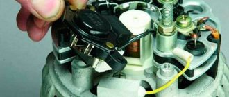
How to remove the relay regulator
Removing the generator voltage regulator relay (“Lanos” or domestic “nine” is not important) is quite simple. It is worth noting that when replacing the voltage regulator, you only need one tool - a flat-head or Phillips screwdriver. There is no need to remove the generator or the belt and its drive. Most of the devices are located on the back cover of the generator, and are combined into a single unit with a brush mechanism. The most common breakdowns occur in several cases.
Firstly, when completely erasing the graphite brushes. Secondly, in case of breakdown of a semiconductor element. How to check the regulator will be discussed below. When removing, you will need to disconnect the battery. Disconnect the wire that connects the voltage regulator to the generator output. By unscrewing both mounting bolts, you can pull out the device body. But the voltage regulator relay for the VAZ 2101 generator has an outdated design - it is mounted in the engine compartment, separately from the brush assembly.
Device check
The relay-regulator of the voltage of the VAZ 2106 generator, “kopecks”, and foreign cars is checked equally. As soon as you remove it, look at the brushes - they should be more than 5 millimeters long. If this parameter is different, the device must be replaced. To carry out diagnostics, you will need a constant voltage source. It would be desirable to be able to change the output characteristic. You can use a battery and a couple of AA batteries as a power source. You also need a lamp, it must run on 12 Volts. You can use a voltmeter instead. Connect the plus from the power supply to the voltage regulator connector.
Accordingly, connect the negative contact to the common plate of the device. Connect a light bulb or voltmeter to the brushes. In this state, voltage should be present between the brushes if 12-13 Volts are supplied to the input. But if you supply more than 15 Volts to the input, there should be no voltage between the brushes. This is a sign that the device is working properly. And it doesn’t matter at all whether the voltage regulator relay of the VAZ 2107 generator or another car is diagnosed. If the control lamp lights up at any voltage value or does not light up at all, it means that there is a malfunction of the unit.
DIY crafts for car enthusiasts
We have already looked at many voltage regulator circuits for a variety of purposes, today I will show you three simple DC regulator circuits that are worth adopting, as they are universal and can be used not only in chargers, but also in many home-made designs , including laboratory power supplies.
The current regulator, in theory, is not much different from the voltage regulator; it is worth noting that there is the concept of a current stabilizer.
Unlike a regulator, it maintains a stable output current regardless of the input voltage and output load.
Today we will look at a couple of stabilizer options and one regulator for general use. A current stabilizer is an integral part of any normal laboratory power supply or charger; it is designed to limit the current supplied to the load.
An important point... in all three options, shunts are used as a current sensor, essentially low-resistance resistors; to increase the output current of any of the listed circuits, it will be necessary to reduce the shunt resistance experimentally.
By the way, you will find links to all printed circuit boards at the end of the article. The required current value is set manually, usually by rotating a variable resistor.
All three options that we will consider today operate in linear mode, which means the power element is a transistor. Under heavy loads it will heat up and need cooling.
I will try to explain the principle of operation of the circuits in as simple words as possible...
The first circuit is characterized by maximum simplicity and accessibility of components, only two transistors, one of them is the control one, the second is the power one, through which the main current flows.
The current sensor or shunt is a low-resistance wire-wound resistor; when an output load is connected, a certain voltage drop is formed across this resistor; the more powerful the load, the greater the drop.
This voltage drop is enough to trigger the control transistor; the greater the drop, the more this transistor is slightly open.
Resistor R1 sets the bias voltage for the power transistor; it is thanks to it that the main transistor is in the open state.
Current limitation occurs due to the fact that the voltage at the base of the power transistor, which was formed by resistor R1, is roughly damped or shorted to the power supply positive through the open junction of the low-power transistor. This will close the power transistor, therefore the current flowing through it decreases down to complete zero.
Resistor R2 is essentially an ordinary voltage divider, with which we can set the degree of openness of the control transistor, and therefore control the power transistor, limiting the current flowing through it.
The total switching current of this circuit can be increased by using additional power transistors connected in parallel.
Since the characteristics of even identical transistors will differ, resistors are added to their collector circuit; they are designed to equalize the currents through the transistors so that the latter are loaded evenly.
The second circuit is built on the basis of an operational amplifier; it has been repeatedly used in chargers for car batteries; unlike the first option, this circuit is precisely a current stabilizer.
As in the first circuit, there is also a current sensor or shunt, the operational amplifier records the voltage drop across this shunt, all according to the circuit already familiar to us.
The amplifier compares the voltage on the shunt with the reference voltage, which is set by a zener diode.
With a variable resistor we artificially change the reference voltage, the operational amplifier, in turn, will try to balance the voltage at the inputs by changing the output voltage.
The output of the operational amplifier is controlled by a high-power field-effect transistor.
That is, the principle of operation differs little from the first circuit, except that there is a reference voltage source in the form of a zener diode.
This circuit also operates in linear mode and the power transistor will get very hot under heavy loads and needs a heatsink; by the way, it is possible to use bipolar transistors.
The latest circuit is built on the basis of the popular LM317 stabilizer integrated circuit; it is a linear voltage stabilizer, but it is possible to use the chip as a current stabilizer.
The required current is set by a variable resistor. The disadvantage of the circuit is that the main current flows precisely through the previously indicated resistor and naturally it needs a powerful one; the use of wirewound resistors is highly desirable.
Enter your email and receive emails with new crafts.
The maximum permissible current for the LM317 microcircuit is about one and a half amperes, it can be increased with an additional power transistor,
in this case, the microcircuit will already act as a control chip, therefore it will not heat up.
In return, the transistor will heat up and there is no escape from this.
Archive for the article;
Author; AKA Kasyan
Popular;
- Simple voltage regulator on LM317, circuit
- Voltage converter +U to -U on CD4049 microcircuit, circuit.
- Voltage stabilizer with adjustable load for charger
- Charger circuits (using LM317, LM338)
- Low-power laboratory power supply based on LM317
- Current stabilizer for LEDs
- Three power supplies for the car from 24 to 12 volts.
- Simple voltage stabilizer for the charger
conclusions
In the electrical system of a car, the voltage regulator relay of the Bosch generator (as, indeed, of any other company) plays a very important role. Monitor its condition as often as possible and check for damage and defects. Cases of failure of such a device are not uncommon. In this case, in the best case, the battery will be discharged. And in the worst case, the supply voltage in the on-board network may increase. This will lead to the failure of most electricity consumers. In addition, the generator itself may fail. And its repair will cost a tidy sum, and considering that the battery will fail very quickly, the costs will be astronomical. It is also worth noting that the Bosch generator voltage regulator relay is one of the leaders in sales. It has high reliability and durability, and its characteristics are as stable as possible.
Possible causes of malfunctions and consequences
The need to repair the generator voltage regulator relay will arise when the following problems occur:
- interturn closure of the winding device;
- short circuit in the electrical circuit;
- breakdown of the rectifier element as a result of diode breakdown;
- errors made when connecting the generating set to the battery terminals, reversal;
- water or other liquid entering the body of the control device, for example, in high humidity on the street or when washing a car;
- mechanical failures of the device;
- natural wear and tear of structural elements, in particular brushes;
- low quality of the device used.
As a result of a malfunction, the consequences can be serious:
- High voltage in the vehicle's electrical network will lead to electrical equipment failure. The microprocessor control unit of the machine may fail. Therefore, it is not allowed to disconnect the battery terminals while the power unit is running.
- Overheating of the winding device as a result of an internal short circuit. Repairs will be expensive.
- Failure of the brush mechanism will cause the generator set to malfunction. The unit may jam and the drive belt may break.
User Snickerson talked about diagnosing the regulatory mechanism, as well as the reasons for its failure on cars.
Remote controller
ATTENTION! A completely simple way to reduce fuel consumption has been found! Don't believe me? An auto mechanic with 15 years of experience also didn’t believe it until he tried it. And now he saves 35,000 rubles a year on gasoline! Read more"
This often happens to drivers. The brushes of the generating device burn out. The regulator is built in along with the brushes. We have to change everything together. And here’s some advice from experts: it’s better to install an external regulator than a built-in one. The models released recently have not been praised very much.
Okay, do you think I’ll install an external one, but how do I connect it? It turns out that there is a convenient scheme that makes it easy to carry out all this modernization.
Some important points:
- do not confuse the chips on the regulator numbered 67 and 15 (the first should be connected to the generating device, and the second should go to the fuses);
This is what the connection diagram looks like
In the lower photo we see a diagram that shows the connection of the already built-in regulator relay.
It is suitable for connecting to “fives”, “sevens”, VAZ 2104, if the PG is installed from a VAZ “kopek”. As you can see, the remote-type regulator relay is connected via two terminals. Pin 15 goes to the fuse.
The second pin 67 is connected to the generator. The wire is connected to the brush chip.
Also, the remote-type relay must be connected to ground - any part of the body.
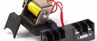
A relay is nothing more than a switch that serves to close and disconnect individual zones of an electrical circuit that occur at specific electrical values. A machine relay is otherwise called a load voltage switch, and this is 100 percent true. When the power supply unit, fan or starter consumes more current than necessary, the relay trips.
The relay consists of an electric type magnet, an armature and a switch. In this case, the electromagnet is a cable twisted around an inductor with a magnetic rod, and the armature is a special plate that controls the contacts.
As soon as electrical voltage passes through the magnet winding, an electric field is created. A special pusher presses the armature against the core and, thereby, the contacts switch.
Attention. There are two types of relays used on VAZ cars. This is a non-contact relay-regulator and MER (electric). It is the diagram of the last relay that is shown in the picture below.
The non-contact relay or NERR is a fairly new unit that does not require any additional adjustments or regulation. As for the MED, this is an old-style device, the production of which has currently been suspended.
So, the BRN or built-in regulator is a device consisting of a microcircuit, a transistor and a housing with brushes. If the built-in regulator fails, it is replaced with a new one, or an external one is installed.
The external regulator is easy to install if you strictly follow the instructions.
Modernization involves dismantling and disassembling the generating device.
GU or generator
The generator in any automotive electrical circuit performs the dominant functions. The normal functioning and operation of the machine depends on it. Reliable PG is installed in all foreign cars and models of the domestic automobile industry.
For example, a GU is placed on the “six”, the charge of which satisfies the need for electricity of any standard component. If you do not overload the generating device of the “six”, then the car is capable of driving many, many more kilometers. However, it is important to carry out preventive procedures in a timely manner - monitor the belt tension and the condition of the brushes.
The GU is connected according to the classical scheme. Using the VAZ 2106 generator as an example, let’s consider its functioning. This GU is marked as G-221. It is an AC synchronous electric machine with ELMG excitation. A VB (rectifier) with 6 diodes is built inside the GU.
| 1 | generator rotor winding |
| 2 | generator |
| 3 | generator stator winding |
| 4 | generator rectifier |
| 5 | accumulator battery |
| 6 | ignition switch |
| 7 | battery charge indicator lamp |
| 8 | battery warning light relay |
| 9 | fuse box VAZ -2106 |
| 10 | throttle |
| 11 | temperature compensation resistor |
| 12 | additional resistors |
| 13 | voltage regulator |
A simple and understandable scheme that does not require any subtleties or specific knowledge. On the “six” the PG is located on the engine on the right. It is attached to the tension bar with a nut and to the bracket with its claws.
As you can see, the diagram shows an external regulator. It is marked with the number 13. The generator is indicated with the number 2, the fuse box is indicated with the number 9.
Generator connection diagram for VAZ 2107
The VAZ 2107 charging scheme depends on what type of generator is used. To recharge the battery on cars such as VAZ-2107, VAZ-2104, VAZ-2105, which have a carburetor engine, you will need a G-222 type generator or its equivalent with a maximum output current of 55A. In turn, VAZ-2107 cars with an injection engine use a generator 5142.3771 or its prototype, which is called a high-energy generator, with a maximum output current of 80-90A. It is also possible to install more powerful generators with an output current of up to 100A. Absolutely all types of alternating current generators have built-in rectifier units and voltage regulators; they are usually made in the same housing with brushes or are removable and mounted on the housing itself.
The VAZ 2107 charging circuit has minor differences depending on the year of manufacture of the car. The most important difference is the presence or absence of a charge indicator lamp, which is located on the instrument panel, as well as the method of connecting it and the presence or absence of a voltmeter. Such circuits are mainly used on carburetor cars, while on cars with injection engines the circuit does not change, it is identical to those cars that were manufactured previously.
Generator set designations:
- “Plus” of the power rectifier: “+”, V, 30, V+, WAT.
- “Ground”: “-”, D-, 31, B-, M, E, GRD.
- Excitation winding output: Ш, 67, DF, F, EXC, E, FLD.
- Output for connection to the serviceability lamp: D, D+, 61, L, WL, IND.
- Phase output: ~, W, R, STA.
- Output of the stator winding zero point: 0, MP.
- Output of the voltage regulator for connecting it to the on-board network, usually to the “+” of the battery: B, 15, S.
- Voltage regulator output for powering it from the ignition switch: IG.
- Voltage regulator output for connecting it to the on-board computer: FR, F.
Scheme of the VAZ-2107 generator type 37.3701
- Accumulator battery.
- Generator.
- Voltage regulator.
- Mounting block.
- Ignition switch.
- Voltmeter.
- Battery charge indicator lamp.
When the ignition is turned on, the plus from the lock goes to fuse No. 10, and then goes to the battery charge indicator lamp relay, then goes to the contact and to the coil output. The second terminal of the coil interacts with the central terminal of the starter, where all three windings are connected. If the relay contacts close, then the control lamp lights up. When the engine starts, the generator generates current and an alternating voltage of 7V appears on the windings. Current passes through the relay coil and the armature begins to attract, and the contacts open. Generator No. 15 passes current through fuse No. 9. Similarly, the excitation winding receives power through the brush voltage generator.
Removing and installing the voltage regulator
Replacing the external voltage regulator VAZ 2101-2106
1) Using the “8” socket, unscrew the two nuts and remove the regulator.
2) Disconnect the two wires.
3) Attach the new regulator to the mudguard and connect the wires: orange to terminal “15”, and gray to terminal “67”.
Voltage regulator relay connection diagram
ATTENTION! Before starting the engine, make sure that the contact between the voltage regulator housing and the vehicle ground is reliable, and that the wires to terminals “15” and “67” are connected correctly.
Issues of selection, diagnostics and replacement of voltage relay regulators
Various malfunctions can occur in relay regulators, which in most cases are manifested by a lack of battery charging current and, on the contrary, an excessive battery charging current. The simplest check of the regulator can be carried out using a voltmeter - just start the engine and let it run for 10-15 minutes at a frequency of 2500-3000 rpm and with the headlights on. Then, without reducing the speed and without turning off the headlights, measure the voltage at the battery terminals - it should be 14.1-14.3 volts (twice as high for 24-volt ones). If the voltage is significantly lower or higher, then this is a reason to check the generator, and if it is in order, replace the regulator.
The replacement should be a relay-regulator of the same type and model that was installed previously
You especially need to pay attention to the order in which the regulator is connected to the on-board network (to which terminals of the generator and other elements), as well as to the supply voltage and currents. Replacement of the part must be carried out according to the instructions; work can only be carried out with the engine stopped and the terminal removed from the battery
If all recommendations are followed and the regulator is selected correctly, it will immediately begin to work, ensuring the normal functioning of the electrical system.