Purpose and principle of operation
Using voltage regulators, you can change not only the brightness of incandescent lamps, but also the rotation speed of electric motors, the temperature of the soldering iron tip,
and so on. These devices are often called power regulators, which is not entirely correct. Devices designed to regulate power are based on PWM (pulse width modulation) circuits.
This allows you to obtain different pulse repetition rates at the output, the amplitude of which remains unchanged. However, if a voltmeter is connected in parallel to the load in such a circuit, the voltage will also change. The fact is that the device simply does not have time to accurately measure the amplitude of the pulses.
It should be noted that voltage regulators will be most effective when working with resistive loads, such as incandescent lamps. But using them to connect to an inductive load is impractical. The fact is that the inductive current is much lower compared to resistive current.
Assembling a homemade dimmer is quite simple. This will require some basic knowledge of electronics and a few parts.
Based on triac
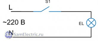
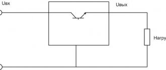
Such a device operates on the principle of phase shift of key opening. Below is the simplest triac-based dimmer circuit:
Structurally, the device can be divided into two blocks:
- A power switch, in the role of which a triac is used.
- Unit for creating control pulses based on a symmetrical dinistor.
A voltage divider is created using resistors R1-R2
It should be noted that resistance R1 is variable. This allows you to change the voltage in line R2-C1
A DB3 dinistor is connected between these elements. As soon as the voltage indicator on capacitor C1 reaches the opening threshold of the dinistor, a control pulse is applied to the switch (triac VS1).
Thyristor based
These partings are also quite effective, and their patterns are not very complicated. The role of the key in such a device is performed by a thyristor. If you carefully study the circuit diagram of the device, you will immediately notice the main difference between this circuit and the previous one - for each half-wave, its own switch with a control dinistor is used.
The operating principle of the thyristor device is as follows:
- When a positive half-wave passes through line R5-R4-R3, capacitor C1 is charged.
- After reaching the switching threshold of dinistor V3, it is triggered, and electric current flows to switch V1.
- When a negative half-wave passes, a similar situation is observed for the line R1-R2-R5, the control dinistor V4 and the key V2.
Capacitor regulators are also used in everyday life. However, unlike semiconductor devices, they do not allow smooth voltage changes. Thus, thyristor and triac circuits are best suited
.
Finding all the parts needed to make the regulator is not difficult. However, you don’t have to buy them, but can be removed from an old TV or other radio equipment. If desired, you can make a printed circuit board based on the selected circuit, and then solder all the elements into it. The parts can also be connected using regular wires. The home master can choose the method that seems most attractive to him.
Both devices discussed are quite easy to assemble, and you don’t need to have serious knowledge in the field of electronics to complete all the work. Even a novice radio amateur can make a 220V voltage regulator circuit with his own hands. At a low cost, they are practically in no way inferior to their factory counterparts.
Operating principle of phase control
The principle of regulation of this type is that the pulse that opens the thyristor has a certain phase. That is, the further it is located from the end of the half-cycle, the greater the amplitude will be the voltage supplied to the load. In the figure below we see the reverse process, when the pulses arrive almost at the end of the half-cycle.
Minimum power
The graph shows the time when the thyristor is closed t1 (phase of the control signal), as you can see, it opens almost at the end of the half-cycle of the sinusoid, as a result, the voltage amplitude is minimal, and therefore, the power in the load connected to the device will be insignificant (close to the minimum). Consider the case presented in the following graph.
Half power
Here we see that the pulse that opens the thyristor occurs in the middle of the half-cycle, that is, the regulator will output half the maximum possible power. Operating at close to maximum power is shown in the following graph.
Power close to maximum
As can be seen from the graph, the pulse occurs at the beginning of the sinusoidal half-cycle. The time when the thyristor is in the closed state (t3) is insignificant, so in this case the power in the load approaches the maximum.
Note that three-phase power regulators work on the same principle, but they control the voltage amplitude not in one, but in three phases at once.
This control method is easy to implement and allows you to accurately change the voltage amplitude in the range from 2 to 98 percent of the nominal value. Thanks to this, smooth control of the power of electrical installations becomes possible. The main disadvantage of devices of this type is the creation of a high level of interference in the electrical network.
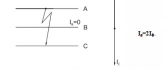
An alternative to reduce noise is to switch the thyristors when the AC voltage sine wave passes through zero. The operation of such a power regulator can be clearly seen in the following graph.
Switching the thyristor through “zero”
Designations:
- A – graph of half-waves of alternating voltage;
- B – thyristor operation at 50% of maximum power;
- C – graph displaying the operation of the thyristor at 66%;
- D – 75% of maximum.
As can be seen from the graph, the thyristor “cuts off” half-waves, not parts of them, which minimizes the level of interference. The disadvantage of this implementation is the impossibility of smooth regulation, but for loads with high inertia (for example, various heating elements), this criterion is not the main one.
Video: Testing a thyristor power regulator
Replacing a triac in a dimmer
Hollow rivets can be removed using a 90° drill bit or side cutters. But in order not to damage the radiator, this must be done from the side where the triac is located.
The radiators, made of very soft aluminum, were slightly deformed when riveted. Therefore, I had to sand the contact surfaces with sandpaper.
- Screw M2.5x8.
- Spring washer (grower) M2.5.
- Washer M2.5 – fiberglass.
- Triac case.
- Gasket – fluoroplastic 0.1mm.
- Nut M2.5.
- Washer M2.5.
- Tube (cambric) Ø2.5x1.5mm.
- Washer M2.5.
- Radiator.
Since I used a triac that does not have galvanic isolation between the electrodes and the contact pad, I used the old proven isolation method. The drawing shows how it is implemented.
And these are the same parts of the galvanic isolation of the triac in its natural form.
To prevent the radiator wall from pressing through at the location where the triac is attached, a washer was placed under the screw head. And most of the head of the screw itself was ground off so that it would not cling to the handle of the potentiometer and power regulator.
This is what a triac isolated from the radiator looks like. To improve heat dissipation, thermal conductive paste KPT-8 was used.
What's under the dimmer housing?
Back in action.
What is a 220 V voltage regulator
The abbreviated name of the device in question is RN 0–220 V. The simplest such device is a dimmer for incandescent lamps. The device adjusts the network voltage parameters, increases/decreases the degree of the output signal in a range depending on the value of the potential difference at its output. Maintains the specified voltage of the consumer circuit.
The device regulates (smoothly or stepwise) precisely the voltage value itself, the voltage, on which the power in the range of capabilities of the connected unit also depends. It works with reactive and active loads, you just need to check whether a particular assembly is suitable, especially for the latter. And also you always need to compare what power (Watts) the circuit is designed for.
The RN changes, according to user settings, the level of the output signal from the 220 V network supplied to the load connected to it. Thus, a parameter is set that is suitable for powering a particular device, and more often for adjusting its operation (reducing/increasing the speed of low-power electric motors, light brightness).
The voltage regulator is used:
- to change the speed of small motors of household devices (the speed of a blender, hair dryer), less often, since not all circuits are suitable, for more powerful motors (for example, a drill);
- for other devices whose operation can be customized. And more often (and this is the most correct and effective use) for the light level (dimmer), sound volume, heating of heating elements, soldering iron,
- in all cases, if it is necessary to create a certain voltage on the circuit, for example, 12 V.
Most often, household pH 0–220 V is used for smooth on/off. devices.
Factory models usually also have a microcircuit for stabilizing voltage during voltage surges, ensuring the operation of devices in any mode. According to English standards, a thyristor regulator is called Voltage Controller. RNs are supplied with universal power supplies on which the voltage can be adjusted.
Types, principle of operation, features
The RN on our topic is intended only for alternating voltage, that is, for a regular 220 V home network.
Most often they are assembled based on the following parts:
- thyristors;
- triacs;
- transistors.
The circuits also contain capacitors, constant and tuning resistors. It is the selectors of the latter that carry out the adjustment. Complex assemblies may include microchips.
RNs are most effective for resistive (reactive, ohmic) loads, that is, those that are part of the power consumption of the connected/disconnected consumer. This is resistance to the flow of current, such as a resistor, at the point where electricity is converted into heat.
Resistive loads are heating elements, heating elements, incandescent lamps (not “housekeepers”).
In an inductive load, the current (where it is much lower than with a resistive load) lags behind the voltage, and reactive power is created. These are asynchronous electric motors, electromagnets, chokes, transformers, rectifiers. The launch vehicles will not work with them, or they will, but not effectively, creating a risk of equipment failure. There voltage regulators are not always appropriate.
The thyristor device cannot be used with LED (economical) and fluorescent lamps. Capacitor regulators do not allow smooth voltage changes.
Assembling the device
We will not describe all standard assembly actions; we will only note the main points. The transistor must be placed on a heat sink. Why? Because the circuit is linear and at high currents the transistor will get very hot. What is the radiator made of? It can be made from a regular aluminum corner and attached directly to the power supply fan. And, despite the fact that the radiator is quite small in size, thanks to the intense airflow it will cope with its task perfectly.
A transistor is screwed to the radiator through thermal paste; in this circuit it uses a field-effect, N-channel IRFZ44 with a maximum current of 49 A. Since the radiator is isolated from the main board and case, the transistor is screwed directly without insulating spacers.
The stabilizer board is fixed to the same aluminum corner through a brass stand. To regulate the output current, a 5 kOhm variable resistor is used. The wires are secured with plastic ties to prevent them from dangling.
As a result, you should get the following connection diagram for this stabilizer for the charger.
The power supply can be absolutely anything, either a computer power supply or a regular transformer. The cord used to connect to the outlet is a regular computer one.
All is ready. You can now use such an adjustable voltage stabilizer for the charger. It should be noted that the circuit is simple and inexpensive: it simultaneously functions as a stabilizer and a charger.
DIY thyristor voltage regulator
This cannot be said that this circuit will not provide galvanic isolation from the power source, so there is a certain danger of electric shock. This will mean that you do not need to touch the regulator elements with your hands.
You should design the design of your device in such a way that, if possible, you can hide it in an adjustable device , and also find more free space inside the case. If the adjustable device is located at a stationary level, then it makes some sense to connect it through a switch with a special light brightness control. Such a solution can partially protect a person from electric shock, and will also relieve him of the need to find a suitable housing for the device, has an attractive external structure, and is also created using industrial technologies.
Thyristor circuits
You can regulate the total power of the soldering iron quite simply if you use analog or digital soldering stations for this. The latter are quite expensive to use, and it is quite difficult to assemble them without much experience. While analog devices (considered to be essentially total power regulators) are not difficult to create yourself.
A fairly simple circuit of the device that will help regulate the power indicator on the soldering iron.
- VD - KD209 (or similar in its general characteristics).
- R 1 - resistance with a special rating of 15 kOhm.
- R2 is a resistor that has a special AC current rating of about 30 kOhm.
- Rn is the total load (in this case a special pendulum will be used instead).
Such a regulation device can control not only the positive half-cycle; for this reason, the power of the soldering iron will be several times less than the nominal one. Such a thyristor is controlled using a special circuit, which carries two resistances, as well as a capacitance. The charging time of the condensate (it will be regulated by a special resistance R2) affects the duration of opening of such a thyristor.
How does such a device work?
The characteristics described below will correspond to most circuits.
- A thyristor total power regulator, the principle and operating features of which will be based on the phase control of the voltage value, also changes the total power in the devices. This feature lies in the fact that under normal production conditions the load can be affected by approximate voltage indicators of the household network, which will change in accordance with the sinusoidal law. Above, when describing the principle of operation of a thyristor, it was said that any thyristor includes operation in only one direction, that is, it controls its half-wave from sinusoids. What could this mean?
- If, using a device such as a thyristor, a load is connected over time at a strictly defined time, then the effective voltage indicator will be quite low, since half of the voltage (the effective value, which reproduces the load) will be much less than the light voltage. This phenomenon can be seen on motion graphs.
In this case, there is a certain area that will be under special stress. When the effect of the positive half-wave ends and a new period of movement with a negative half-wave begins, one of these thyristors will begin to close, and at the same time a new thyristor will open.
Instead of the words positive and negative wave, you should use the first and second (half-wave).
While the first half-wave begins to influence the circuit, a special charging of the capacitance C1 and also C2 occurs . The speed of their full charging will be limited by potentiometer R 5. Such an element will be completely variable, and with its help the output voltage will be set. At the moment when the voltage necessary to open diristor VS 3 appears on the surface of capacitor C1, the entire dinistor will open, and a current will begin to pass through it, with the help of which thyristor VS 1 will open.
During the breakdown of the dinistra, a point is formed on the general chart. After the voltage value passes the zero mark, and the circuit is under the influence of the second half-wave, the thyristor VS 1 will close, and the process will be repeated, only for the second dinistor, thyristor, and also the capacitor. Resistors R 3 and R 3 are needed to limit the total control current, and R 1 and R 2 are needed for the process of thermal stabilization of the entire circuit.
The principle of operation of the second circuit will be exactly the same, but it will control only one of the half-waves of alternating current. After the user understands the principle of operation of the device and its general structure, he will be able to understand how to assemble or, if necessary, repair the thyristor power regulator himself.
Scheme number 1
There was a stabilized switching power supply that gave an output voltage of 17 volts and a current of 500 milliamps. A periodic change in voltage was required in the range of 11 - 13 volts. And the well-known voltage regulator circuit on one transistor coped with this perfectly. I added only an indication LED and a limiting resistor to it. By the way, the LED here is not only a “firefly” signaling the presence of output voltage. With the correct value of the limiting resistor, even a small change in the output voltage is reflected in the brightness of the LED, which provides additional information about its increase or decrease. The output voltage could be changed from 1.3 to 16 volts.
KT829, a powerful low-frequency silicon compound transistor, was installed on a powerful metal radiator and it seemed that, if necessary, it could easily withstand a heavy load, but a short circuit occurred in the consumer circuit and it burned out. The transistor has a high gain and is used in low-frequency amplifiers - you can really see its place there and not in voltage regulators.
On the left are removed electronic components, on the right are prepared for replacement. The difference in quantity is two items, but in terms of the quality of the circuits, the former and the one that was decided to be collected, it is incomparable. This begs the question: “Is it worth assembling a scheme with limited capabilities when there is a more advanced option “for the same money”, in the literal and figurative sense of this saying?”
Using the regulator in everyday life and safety precautions
It must be said that this circuit does not provide galvanic isolation from the network, so there is a danger of electric shock. This means that you should not touch the regulator elements with your hands. An insulated housing must be used. You should design the design of your device so that, if possible, you can hide it in an adjustable device and find free space in the case. If the adjustable device is located permanently, then in general it makes sense to connect it through a switch with a dimmer. This solution will partially protect against electric shock, eliminate the need to find a suitable housing, has an attractive appearance and is manufactured using an industrial method.
In electrical engineering, one often encounters problems of regulating alternating voltage, current or power. For example, to regulate the rotation speed of the shaft of a commutator motor, it is necessary to regulate the voltage at its terminals; to control the temperature inside the drying chamber, it is necessary to regulate the power released in the heating elements; to achieve a smooth, shock-free start of an asynchronous motor, it is necessary to limit its starting current. A common solution is a device called a thyristor regulator.
Design and principle of operation of a single-phase thyristor voltage regulator
Thyristor regulators are single-phase and three-phase, respectively, for single-phase and three-phase networks and loads. In this article we will look at the simplest single-phase thyristor regulator, three-phase ones - in other articles. So, Figure 1 below shows a single-phase thyristor voltage regulator:
Fig. 1 Simple single-phase thyristor regulator with active load
The thyristor regulator itself is outlined in blue lines and includes thyristors VS1-VS2 and a pulse-phase control system (hereinafter referred to as SIFC). Thyristors VS1-VS2 are semiconductor devices that have the property of being closed for the flow of current in the normal state and being open for the flow of current of the same polarity when a control voltage is applied to its control electrode. Therefore, to operate in alternating current networks, two thyristors are required, connected in different directions - one for the flow of the positive half-wave of current, the second for the negative half-wave. This connection of thyristors is called back-to-back.
Single-phase thyristor regulator with active load
This is how a thyristor regulator works. At the initial moment of time, voltage LN is applied (phase and zero in our example), while control voltage pulses are not supplied to the thyristors, the thyristors are closed, and there is no current in the load Rн. After receiving a command to start, the SIFU begins to generate control pulses according to a specific algorithm (see Fig. 2).
Fig.2 Diagram of voltage and current in an active load
First, the control system synchronizes with the network, that is, it determines the point in time at which the LN network voltage is zero. This point is called the moment of crossing zero (in foreign literature - Zero Cross). Next, a certain time T1 is counted from the moment of zero crossing and a control pulse is applied to the thyristor VS1. In this case, the thyristor VS1 opens and current flows through the load along the path L-VS1-Rн-N. When the next zero crossing is reached, the thyristor automatically turns off, since it cannot conduct current in the opposite direction. Next, the negative half-cycle of the mains voltage begins. SIFU again counts time T1 relative to the new moment when the voltage crosses zero and generates a second control pulse with thyristor VS2, which opens, and current flows through the load along the path N-Rн-VS2-L. This method of voltage regulation is called phase-pulse
.
Time T1 is called the delay time for unlocking the thyristors, time T2 is the conduction time of the thyristors. By changing the unlocking delay time T1, you can adjust the output voltage from zero (pulses are not supplied, the thyristors are closed) to full network voltage, if pulses are supplied immediately at the moment of crossing zero. The unlocking delay time T1 varies within 0..10 ms (10 ms is the duration of one half-cycle of the standard 50 Hz network voltage). They also sometimes talk about times T1 and T2, but they operate not with time, but with electrical degrees. One half-cycle is 180 electrical degrees.
What is the output voltage of a thyristor regulator? As can be seen from Figure 2, it resembles the “cuts” of a sinusoid. Moreover, the longer the T1 time, the less this “cut” resembles a sinusoid. An important practical conclusion follows from this - with phase-pulse regulation, the output voltage is non-sinusoidal. This limits the scope of application - the thyristor regulator cannot be used for loads that do not allow power supply with non-sinusoidal voltage and current. Also in Figure 2 the diagram of the current in the load is shown in red. Since the load is purely active, the current shape follows the voltage shape in accordance with Ohm’s law I=U/R.
The active load case is the most common. One of the most common applications of a thyristor regulator is voltage regulation in heating elements. By adjusting the voltage, the current and the power released in the load change. Therefore, sometimes such a regulator is also called a thyristor power regulator
. This is true, but still a more correct name is a thyristor voltage regulator, since it is the voltage that is regulated in the first place, and current and power are already derivative quantities.
Voltage and current regulation in active-inductive loads
We looked at the simplest case of an active load. Let's ask ourselves the question: what will change if the load, in addition to the active one, also has an inductive component? For example, active resistance is connected through a step-down transformer (Fig. 3). By the way, this is a very common case.
Fig.3 Thyristor regulator operates on RL load
Let's look closely at Figure 2 from the case of a purely active load. It shows that immediately after the thyristor is turned on, the current in the load almost instantly increases from zero to its limit value, determined by the current value of the voltage and load resistance. It is known from the electrical engineering course that inductance prevents such an abrupt increase in current, so the voltage and current diagram will have a slightly different character:
Fig.4 Voltage and current diagram for RL load
After the thyristor is turned on, the current in the load increases gradually, due to which the current curve is smoothed out. The higher the inductance, the smoother the current curve. What does this give practically?
— The presence of sufficient inductance makes it possible to bring the current shape closer to a sinusoidal one, that is, the inductance acts as a sine filter. In this case, this presence of inductance is due to the properties of the transformer, but often inductance is introduced deliberately in the form of a choke.
— The presence of inductance reduces the amount of interference distributed by the thyristor regulator through the wires and into the radio air. A sharp, almost instantaneous (within a few microseconds) increase in current causes interference that can interfere with the normal operation of other equipment. And if the supply network is “weak”, then something completely curious happens - the thyristor regulator can “jam” itself with its own interference.
Read also: Milling and copying machine for metal
— Thyristors have an important parameter - the value of the critical rate of current rise di/dt. For example, for the SKKT162 thyristor module this value is 200 A/µs. Exceeding this value is dangerous, as it can lead to failure of the thyristor. So, the presence of inductance allows the thyristor to remain in the safe operation area, guaranteed not to exceed the limit value di/dt. If this condition is not met, then an interesting phenomenon can be observed - failure of the thyristors, despite the fact that the thyristor current does not exceed their nominal value. For example, the same SKKT162 may fail at a current of 100 A, although it can operate normally up to 200 A. The reason will be the excess of the current rise rate di/dt.
By the way, it must be noted that there is always inductance in the network, even if the load is purely active. Its presence is due, firstly, to the inductance of the windings of the supply transformer substation, secondly, to the intrinsic inductance of the wires and cables and, thirdly, to the inductance of the loop formed by the supply and load wires and cables. And most often, this inductance is enough to ensure that di/dt does not exceed the critical value, so manufacturers usually do not install chokes in thyristor regulators, offering them as an option to those who are concerned about the “cleanliness” of the network and the electromagnetic compatibility of devices connected to it.
Let’s also pay attention to the voltage diagram in Figure 4. It also shows that after crossing zero, a small surge of voltage of reverse polarity appears at the load. The reason for its occurrence is the delay in the decline of current in the load by inductance, due to which the thyristor continues to be open even with a negative half-wave voltage. The thyristor is turned off when the current drops to zero with some delay relative to the moment of crossing zero.
Inductive load case
What happens if the inductive component is much larger than the active component? Then we can talk about the case of a purely inductive load. For example, this case can be obtained by disconnecting the load from the output of the transformer from the previous example:
Figure 5 Thyristor regulator with inductive load
A transformer operating in no-load mode is an almost ideal inductive load. In this case, due to the large inductance, the turning off moment of the thyristors shifts closer to the middle of the half-cycle, and the shape of the current curve is smoothed out as much as possible to an almost sinusoidal shape:
Figure 6 Current and voltage diagrams for the case of inductive load
In this case, the load voltage is almost equal to the full network voltage, although the unlocking delay time is only half a half-cycle (90 electric degrees). That is, with a large inductance, we can talk about a shift in the control characteristic. With an active load, the maximum output voltage will be at an unlocking delay angle of 0 electrical degrees, that is, at the moment of crossing zero. With an inductive load, the maximum voltage can be obtained at an unlocking delay angle of 90 electrical degrees, that is, when the thyristor is unlocked at the moment of maximum mains voltage. Accordingly, in the case of an active-inductive load, the maximum output voltage corresponds to the unlocking delay angle in the intermediate range of 0..90 electrical degrees.
A thyristor is one of the most powerful semiconductor devices, which is why it is often used in powerful energy converters. But it has its own specific control: it can be opened by a current pulse, but it will close only when the current drops almost to zero (to be more precise, below the holding current). From this, thyristors are mainly used for switching alternating current.
DIY soldering iron power regulator: proven working circuits (6 pcs)
Not everyone likes to buy unknown things. And some people find it more pleasant to make a soldering iron power regulator with their own hands, because this is also experience. Most circuits are assembled using triacs and thyristors; now they are easier to find than transistors. They are also easier to work with, since they are either open or closed, which allows you to make circuits simpler.
Choose any case
Simple thyristor circuits
When choosing a power regulator circuit for a soldering iron, two things are important: power and parts availability. The soldering iron power regulator presented below is assembled using widely used parts that are not a problem to find. The maximum current is 10 A, which is more than enough to perform any kind of work and for soldering irons with a power of up to 100 W. The thyristor in this circuit is used KU202n
Pay attention to the bridge connection. There are many circuits with connection errors
This option is working. Tested more than once.
Temperature controller circuit for a soldering iron using a thyristor
When assembling the circuit, be sure to place the thyristor on the radiator; the larger it is, the better. The circuit is simple, but when it is turned on, it creates interference. You can’t listen to the radio nearby, and to remove interference, we connect a 200 pF capacitor in parallel with the load, and a choke in series. The choke parameters are selected depending on the regulated load, but since soldering irons are usually no more than 80-100 W, the choke can be made at 100 W. To do this, you will need a ferrite ring with an outer diameter of 20 mm, on which about 100 turns are wound with a wire with a cross-section of 0.4 mm².
Another drawback of the diagram translated above is that the soldering iron “itches” noticeably. Sometimes you can put up with this, sometimes you can’t. To eliminate this phenomenon, you can select the parameters of capacitor C1 so that when the variable resistor is set to maximum, the connected lamp barely glows.
On other elements but also without interference
The above regulator can be used for any load. Let's give another analogue, but using a different element base. You can regulate not only the power/temperature of the soldering iron, but also any other load with a small inductive component.
A modified circuit for regulating the power of a soldering iron and any other load with the ripple effect eliminated
There is pulsation here, but its frequency is high and it will not be perceived by our vision. So it can be used not only as a dimmer for a soldering iron, but also to regulate the light from a regular incandescent lamp. Is a diode bridge needed to regulate the heating power of a soldering iron? It won't hurt, but it's not necessary.
On a thyristor with high sensitivity
This circuit allows you to smoothly change the temperature of the soldering iron from 50% to 100%. There are two indicators - power and power. The power presence LED always lights up when turned on, but at 75% power the glow is brighter. The power indicator changes the intensity of the glow depending on the operating mode.
Power regulator for soldering iron without interference
In order for the regulator to fit into the case of a mobile phone charger, resistances are used of SMD type (1206). All resistors are installed on the board, except for R 10. Some can be composite (we assemble the required value from series-connected resistors).
For normal operation of the circuit, a sensitive thyristor (with a low control current) and a low state holding current (about 1 mA) is required. For example, KT503 (designed for voltage 400 V, control current 1 mA). The rest of the element base is indicated in the diagram.
If assembled, but the voltage is not adjustable
If the assembled regulator does not regulate anything - the temperature of the soldering iron does not change - the problem is in the thyristor. The scheme seems to be working, but nothing happens. The reason is a thyristor with low sensitivity. The currents flowing in the circuit are not sufficient to open. In this case, it is worth installing an analogue with higher sensitivity (lower control currents).
One of the housing options in which you can hide a homemade power regulator for a soldering iron
The regulator may still work, but the soldering iron begins to “itch.” This problem is solved by installing a choke at the output (in front of the soldering iron). The capacity must be selected - it depends on the soldering iron. The second solution is an analog control circuit, and this is a different circuit.
Well, if you have problems with operation, look for either faulty parts or incorrectly selected components. This is usually the problem.
Scheme of a thyristor power regulator with one and two thyristors
A typical circuit for assembling a thyristor power regulator with your own hands is shown in the figure below.
The output voltage of this circuit is from 15 to 215 volts; in the case of using the indicated thyristors installed on heat sinks, the power is about 1 kW. By the way, the switch with the light brightness control is made according to a similar scheme.
If you don't need to fully regulate the voltage and just need to get an output of 110 to 220 volts, use this diagram, which shows a half-wave power regulator on a thyristor.
How to make a current stabilizer for LEDs yourself
Making a stabilizer for LEDs with your own hands is carried out in several ways. It is advisable for a beginner to work with simple circuits.
Driver based
You will need to choose a chip that is difficult to burn out - LM317.
It will act as a stabilizer. The second element is a variable resistor with a resistance of 0.5 kOhm with three terminals and an adjustment knob. Assembly is carried out according to the following algorithm:
- Solder the conductors to the middle and extreme terminals of the resistor.
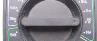
- Set the multimeter to resistance mode.
- Measure the parameters of the resistor - they should be equal to 500 Ohms.
- Check connections for integrity and assemble the circuit.
The output will be a module with a power of 1.5 A. To increase the current to 10 A, you can add a field switch.
Stabilizer for car lighting
Stabilizer L7812
To operate, you will need a linear device in the form of an L7812 microcircuit, two terminals, a 100n capacitor (1-2 pcs.), textolite material and a heat-shrinkable tube. Manufacturing is carried out step by step:
- Selecting a circuit for L7805 from the datasheet.
- Cut out the required size piece from the PCB.
- Mark the paths by making notches with a screwdriver.
- Solder the elements so that the input is on the left and the output is on the right.
- Make a housing from a thermal tube.
The stabilizing device can withstand up to 1.5 A load and is mounted on a radiator.
Let's figure out how our specific thyristor power regulator works
Let us stipulate in advance that instead of the words “positive” and “negative”, “first” and “second” (half-wave) will be used.
So, when the first half-wave begins to act on our circuit, capacitors C1 and C2 begin to charge. Their charging speed is limited by potentiometer R5. this element is variable, and with its help the output voltage is set. When the voltage necessary to open dinistor VS3 appears on capacitor C1, the dinistor opens and current flows through it, with the help of which thyristor VS1 will be opened. The moment of breakdown of the dinistor is point “a” on the graph presented in the previous section of the article. When the voltage value passes through zero and the circuit is under the second half-wave, the thyristor VS1 closes, and the process is repeated again, only for the second dinistor, thyristor and capacitor. Resistors R3 and R3 serve to limit the control current, and R1 and R2 serve to thermally stabilize the circuit.
The principle of operation of the second circuit is similar, but it controls only one of the half-waves of alternating voltage. Now, knowing the principle of operation and the circuit, you can assemble or repair a thyristor power regulator with your own hands.
Current and voltage regulator
The main operating elements of regulators are thyristors, as well as various types of capacitors and resistors. In high-voltage devices, magnetic amplifiers are additionally used. Modulators ensure smooth adjustments, and special filters help smooth out interference in the circuit. As a result, the electric current at the output becomes more stable than at the input.
DC and AC regulators have their own characteristics and differ in their main parameters and characteristics. For example, a DC voltage regulator has higher conductivity with minimal heat loss. The basis of the device is a diode-type thyristor, which provides a high pulse supply due to accelerated voltage conversion. Resistors used in the circuit must withstand a resistance value of up to 8 ohms. Due to this, heat losses are reduced, protecting the modulator from rapid overheating. The DC controller can function normally at a maximum temperature of 40C. This factor must be taken into account during operation. Field-effect transistors are located next to thyristors, since they only pass current in one direction. Due to this, the negative resistance will be maintained at a level not exceeding 8 ohms.
The main difference between the AC regulator is the use of exclusively triode-type thyristors in its design. However, field-effect transistors are used the same as in DC regulators. Capacitors installed in the circuit perform only stabilizing functions. High-pass filters are very rare. All problems associated with high temperatures are solved by installing pulse converters located next to the modulators. AC regulators whose power does not exceed 5 V use low-pass filters. Cathode control in such devices is performed by suppressing the input voltage.
During adjustments in the network, smooth current stabilization must be ensured. At high loads, the circuit is supplemented with reverse direction zener diodes. To connect them together, transistors and an inductor are used. Thus, the current regulator on the transistor performs current conversion quickly and losslessly.
Special attention should be paid to current regulators designed for active loads. The circuits of these devices use triode-type thyristors, capable of passing signals in both directions. The anode current in the circuit decreases during the period when the maximum frequency of this device decreases. The frequency may vary within the limits set for each device. The maximum output voltage will depend on this. To ensure this mode, field-type resistors and conventional capacitors capable of withstanding resistance up to 9 Ohms are used.
Very often, such regulators use pulsed zener diodes that are capable of overcoming the high amplitude of electromagnetic oscillations. Otherwise, as a result of a rapid increase in the temperature of the transistors, they will immediately become inoperative.
Purpose
The power regulator is useful in circuits containing the following electrical devices:
Regulator with motor
- electric motors;
- devices that use compressors in their work;
- household appliances: washing machines, fans, vacuum cleaners;
- electrical tools of various kinds;
- various lighting devices.
A simple example of using a regulator in lighting
. Important! It is not recommended to use a phase regulator in circuits that include refrigerators, computers, televisions and other fine-tuned consumers, changes in the nature of whose operation can lead to damage to the device or other unpredictable consequences.
AC Models
The AC regulator differs in that thyristors are used only of the triode type. In turn, transistors are standardly used in the field-field type. Capacitors in the circuit are used only for stabilization. You can find high-frequency filters in devices of this type, but rarely. Problems with high temperatures in models are solved using a pulse converter. It is installed in the system behind the modulator. Low-frequency filters are used in regulators with a power of up to 5 V. Control of the cathode in the device is carried out by suppressing the input voltage.
Stabilization of the current in the network occurs smoothly. In order to cope with high loads, reverse zener diodes are used in some cases. They are connected by transistors using a choke. In this case, the current regulator must be able to withstand a maximum load of 7 A. In this case, the level of maximum resistance in the system must not exceed 9 Ohms. In this case, you can hope for a quick conversion process.
How does a thyristor do its job?
A thyristor is a controlled semiconductor device that is capable of quickly conducting current in one direction. The word controlled means a thyristor for a reason, since with its help, unlike a diode, which also conducts the total current to only one pole, you can select a separate moment when the thyristor begins the process of conducting current.
The thyristor has three current outputs at once:
- Cathode.
- Anode.
- Controlled electrode.
To allow current to flow through such a thyristor, the following conditions must be met: the part must be located on the circuit itself, which will be under general voltage, and the required short-term pulse must be applied to the control part of the electrode. Unlike a transistor, controlling such a thyristor will not require the user to hold the control signal.
But all the difficulties of using such a device will not end there: the thyristor can be easily closed by interrupting the flow of current into it through the circuit, or by creating a reverse anode-cathode voltage. This will mean that the use of a thyristor in DC circuits is considered quite specific and in most cases completely unreasonable, and in AC circuits, for example, in a device such as a thyristor regulator, the circuit is created in such a way that the condition for closing the device is fully ensured . Any given half-wave will completely cover the corresponding section of the thyristor.
is most likely difficult for you to understand the diagram of its structure . But, there is no need to be upset - the process of functioning of such a device will be described in more detail below.
Design and operating principle
The stabilizer ensures constant current when it deviates.
The stabilizer ensures constant operating current of LED diodes when it deviates from the norm. It prevents overheating and burnout of LEDs, maintains constant flow during voltage surges or battery discharge.
The simplest device consists of a transformer, a rectifier bridge connected to resistors and capacitors. The action of the stabilizer is based on the following principles:
- supplying current to the transformer and changing its limiting frequency to the mains frequency - 50 Hz;
- voltage adjustment to increase and decrease with subsequent frequency equalization to 30 Hz.
The conversion process also uses high-voltage rectifiers. They determine the polarity. Stabilization of the electric current is carried out using capacitors. Resistors are used to reduce interference.
D) Monitoring the health of thyristors
The best models of thyristor voltage regulators diagnose the health of thyristors. This feature is very important not only because it allows you to detect a faulty device in time, but also because sometimes it prevents an even bigger accident. For example, if the load is connected through a transformer, then in the event of an internal break or short circuit of one of the thyristors, a voltage with a constant component is supplied to the transformer, and as a result, the magnetizing current of the transformer sharply increases, leading to intense heating and failure of the transformer. Therefore, a quickly detected malfunction of the thyristor regulator can prevent damage to expensive equipment.
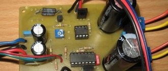
Construction and details.
The regulator is assembled in the power supply housing of the once popular “Electronics B3-36” calculator.
The triac and potentiometer are placed on a steel angle made of steel 0.5 mm thick. The corner is screwed to the body with two M2.5 screws using insulating washers.
Resistors R2, R3 and neon lamp HL1 are dressed in an insulating tube (cambric) and mounted using a hinged mounting method on other electrical elements of the structure.
To increase the reliability of fastening the plug pins, I had to solder several turns of thick copper wire onto them.
This is what the power regulators I've been using for years look like.
| to see this player. |
And this is a 4-second video that allows you to make sure that it all works. The load is a 100 Watt incandescent lamp.
Diagram of a phase power regulator for a 220V load (KU221G)
Schematic diagram of a phase power regulator for a load powered by 220V, which is made using KU221 thyristors. In domestically produced UPIMCT color TVs, which are notorious for the quality of their horizontal scanning units, the BR-13 module used high-voltage SCRs of the KU221 series - three SCRs in each TV.
Currently, surviving copies of such televisions are of interest only to a few collectors, therefore, such televisions that have survived to this day can be freely disassembled for spare parts.
Introduction.
Many years ago, I made a similar regulator when I had to earn extra money repairing radios at a customer’s home. The regulator turned out to be so convenient that over time I made another copy, since the first sample was constantly installed as an exhaust fan speed regulator. https://oldoctober.com/
By the way, this fan is from the Know How series, as it is equipped with an air shut-off valve of my own design. Description of the design >>> The material can be useful for residents living on the top floors of high-rise buildings and who have a good sense of smell.
The power of the connected load depends on the thyristor used and its cooling conditions. If a large thyristor or triac of the KU208G type is used, then you can safely connect a load of 200... 300 Watts. When using a small thyristor, type B169D, the power will be limited to 100 Watts.
Principle of operation
How does our network voltage stabilizer, which is easy to make with your own hands, work?
After the power is turned on, capacitor C1 is in a discharged state, transistor VT2 is open, and VT2 is closed. Transistor VT3 is also closed. It is through it that current will be supplied to each LED and triac optotron.
Since this transistor is off, the LEDs are not lit, each triac is off, and the load is off. At this time, electric current passes through resistor R1 and enters C1. Next, this capacitor is charged.
The delay interval lasts only three seconds. During this time, all transient processes are carried out, and after completion, the Schmitt trigger is triggered, the basis of which is transistors VT1 and VT2.
Next, the third transistor opens and the load is turned on.
The voltage that comes out from the third winding T1 is rectified by the diode VD2 and capacitor C2. Next, the current passes through the divider R13…14. From R14, a voltage whose level is proportional to the number of volts in the network is included in each non-inverting input of the comparators.
The number of comparators is eight and they are all located on chips DA2 and DA3. At the same moment, a constant reference current enters the inverting input of each comparator. It is supplied by resistor dividers R15…23.
After this, the controller comes into play, which processes the signal at the input of each comparator.
- https://electricadom.com/stabilizator-napryazheniya-kak-vse-sdelat-svoimi-rukami-video.html
- https://amperof.ru/sovety-elektrika/sxema-stabilizatora-napryazheniya-220v.html
- https://lifehacker.ru/how-to-make-steadycam/
- https://ostabilizatore.ru/shema-stabilizatora-naprjazhenija-220v-svoimi-rukami.html
- https://fb.ru/article/360616/shema-stabilizatora-napryajeniya-v-svoimi-rukami-dlya-doma
- https://generatorvolt.ru/ehlektrogenerator/kak-sobrat-stabilizator-napryazheniya-svoimi-rukami.html
Types of power regulators
Different power regulators are used for different purposes.
Thyristor control device
The design of the device is quite simple. Typically, thyristors are used in low-power devices. A thyristor thermostat consists of bipolar transistors, the thyristor itself, a capacitor and several resistors.
Thyristor transistor regulator
Transistors form a pulse signal; when the capacitor voltage is equalized with the operating voltage, they open. The electrical signal is transmitted to the output of the thyristor, after which the capacitor is discharged and the key is locked. The entire sequence of actions is repeated cyclically.
Note! The amount of delay is inversely proportional to the power supplied to the load
Triac power converter
A triac is a subtype of a thyristor, in which there are slightly more pn transitions, which is why its operating principle is somewhat different. But a triac is often considered a separate type of power stabilizer. The design consists of 2 thyristors connected in parallel and having common control.
For your information! This is where the name “triac” comes from - “symmetrical thyristors”. Sometimes it is also called TRIAC.
Diagram of 2 parallel connected thyristors (left) and triac (right)
The diagram shows that the triac has the designations T1 and T2 instead of the anode and cathode. This is because the concepts of “cathode” and “anode” in this case do not make sense, since electric current can exit through both terminals.
Triac universal regulators have a number of advantages, including low price, long service life and the absence of moving contacts, which can be sources of interference. But there are also disadvantages: susceptibility to interference and noise, lack of support for high switching frequencies.
Important! They are not used in high-power industrial installations; instead, thyristors or IGBT transistors are used.
Phase transformation method
Phase transformation occurs in so-called dimmers. Such devices are used, for example, to change the lighting intensity of halogen or incandescent lamps. The electrical circuit is usually implemented on special microcontrollers, which use their own integrated voltage reduction circuit. Due to their design, dimmers can smoothly reduce power.
LED dimmer
The disadvantages of such devices are high sensitivity to interference, high ripple factor and low signal power factor at the output. To stabilize the dimmer, dual thyristors are used.
Thyristor check
Before you buy a device, you need to know how to test a thyristor with a multimeter. The measuring device can only be connected to a so-called tester. The diagram by which such a device can be assembled is presented below:
Photo - thyristor tester
According to the description, it is necessary to apply a positive voltage to the anode, and a negative voltage to the cathode. It is very important to use a value that matches the resolution of the thyristor. The drawing shows resistors with a nominal voltage of 9 to 12 volts, which means that the tester voltage is slightly higher than the thyristor. After you have assembled the device, you can begin to check the rectifier. You need to press the button that sends pulse signals to turn it on.
Using modern element base
Old radio components are good because they are “oak” in terms of operational reliability. But they are already really old. For many, their time resource is at its limit and they do not last as long as “fresh” ones. This is the first problem. And secondly, they are becoming increasingly difficult to find. It’s good that there are already many soldering iron regulator circuits based on the new element base. Some of them are simple, others are more complex; various types of modern radio components are used.
Regulator circuit for a soldering iron without interference on the chip
This option cannot be called simple, but it does not emit interference into the network. With so many electronics in every home, this can be important. If you solder only occasionally, you don’t have to pay attention to it. But if you often sit with a soldering iron, interference can cause serious inconvenience.
This circuit can regulate a load of up to 2 kW and provides a smooth change from 0 to maximum.
Homemade soldering iron regulator without interference
According to the element base. The K561LA7 microcircuit can be replaced with a K176LA7. Variable resistor R1 - any of group A. The remaining resistors are better than MLT, capacitors C1, C3 are ceramic. The diodes in the circuit are KD503A; KD514A and KD522A can be replaced. There is also the option of replacing the KT361V transistor with a KT326V or KT361A.
Based on PR1500S phase power regulators
This circuit uses a phase power regulator. Apart from this, the regulator uses only a couple of parts, so assembly time is minimal and it is almost impossible to make a mistake.
DIY soldering iron tip temperature regulator
You will only need a variable resistor, maybe with a switch - then you won’t have to take the soldering iron out of the network. To eliminate interference, you will need a 100 pF capacitor, 630 V, preferably a special film one for filters. The only thing that may be difficult is winding the choke; its parameters are in the table.
Parameters for winding the choke
You will need a ferrite ring with an outer diameter of 20 mm. The greater the permeability of ferrite, the better. This phase regulator can regulate loads up to 1.5 kW, so you can choose any of their columns. You can do it with a reserve, you never know what you want to adjust later. The wire is naturally varnished copper, especially for winding chokes.
What happened after assembly
When assembling for the inductor and phase regulator, it is better to make a heat sink. It is especially useful when working with heavy loads. You can get by with a soldering iron, but you never know, connect it later and it’s better to assemble it right away with a safety margin.
On the optosimistor MOS204x/306x/308x
The circuit has been tested many times and works perfectly without any problems. It is advisable to use optical triacs of the indicated brands, since they open when the voltage crosses zero
The state of the LED does not matter. All others work on a different principle, so the circuit will need to be redone for them. The circuit also contains a 555 series bipolar timer
Finding it is not a problem, the price is normal.
Soldering iron power regulator using optosimistors
All components are selected to have miniature dimensions so that the finished board fits into the case when charging a mobile phone. The value of resistor R5 depends on the type of LED used. On red the voltage drop is 1.6-2 V, on green 1.9-4 V, on yellow 2.1-2.2 V, on blue 2.5-3.7 V. Accordingly, the resistor is selected depending on the actual parameters .
With PWM controller
The modern element base is very extensive, and the same problems can be solved in different ways. For example, use a PWM controller for a power regulator. Any model operating at a frequency of 0.5-1 Hz is suitable for this circuit. The switching element is a field-effect transistor; it can be found on old motherboards or purchased. Its type is not specified, but any n-channel transistor with a voltage of at least 12 V, a current of 6 A and a power of 60 W is suitable.
Soldering iron regulator on a PWM controller and field-effect transistor
The VD3 LED is an optional part of the circuit, but it blinks at different frequencies depending on the heating. Once you get the hang of it, it’s easy to navigate and you don’t have to look at the control knob. But in general, it can be safely thrown out of the scheme
Please note: the power buses from the microcircuit run parallel to the wires, this minimizes the influence of a more powerful load
Diagram of a phase power regulator for a 220V load (KU221G)
Schematic diagram of a phase power regulator for a load powered by 220V, which is made using KU221 thyristors. In domestically produced UPIMCT color TVs, which are notorious for the quality of their horizontal scanning units, the BR-13 module used high-voltage SCRs of the KU221 series - three SCRs in each TV.
Currently, surviving copies of such televisions are of interest only to a few collectors, therefore, such televisions that have survived to this day can be freely disassembled for spare parts.
Scheme number 2
The new circuit also has a three-pin electrical connection. component (but this is no longer a transistor) constant and variable resistors, an LED with its own limiter. Only two electrolytic capacitors have been added. Typically, typical diagrams indicate the minimum values of C1 and C2 (C1=0.1 µF and C2=1 µF) which are necessary for stable operation of the stabilizer. In practice, capacitance values range from tens to hundreds of microfarads. The containers should be located as close to the chip as possible. For large capacities, the condition C1>>C2 is required. If the capacitance of the capacitor at the output exceeds the capacitance of the capacitor at the input, then a situation arises in which the output voltage exceeds the input, which leads to damage to the stabilizer microcircuit. To exclude it, install a protective diode VD1.
This scheme has completely different possibilities. Input voltage is from 5 to 40 volts, output voltage is 1.2 - 37 volts. Yes, there is an input-output voltage drop of approximately 3.5 volts, but there are no roses without thorns. But the KR142EN12A microcircuit, called a linear adjustable voltage stabilizer, has good protection against excess load current and short-term protection against short circuits at the output. Its operating temperature is up to + 70 degrees Celsius, works with an external voltage divider. Output load current is up to 1 A during long-term operation and 1.5 A during short-term operation. The maximum permissible power when operating without a heat sink is 1 W, if the microcircuit is installed on a radiator of sufficient size (100 cm2) then P max. = 10 W.
B) Overheat protection
If the thyristor regulator is installed in a poorly ventilated place, during prolonged overload or if it is difficult to remove the generated heat (for example, when the blower fans fail), the cooling radiator can heat up to a high temperature of 90..100 C. A further increase in temperature can lead to the thyristors leaving the building and even fire. To prevent this, a temperature sensor is installed on the radiator, based on a signal from which the control system de-energizes the load.
Basic functions of the speed controller
The use of such converters allows you to achieve many goals, namely:
- the possibility of stepwise acceleration and reduction of electric motor speed, which leads to reduced loads and less electrical energy consumption;
- you can carry out a smooth start, and with instantaneous maximum acceleration, the motor receives ultra-high loads, overheating the windings and other drives;
- as a means of additional protection of electronic mechanisms;
- reduction in maintenance costs for power units and pumps, as the risks of drive failures, as well as individual mechanisms, are reduced.
Welding machines, voltage stabilizers, PCs, TVs, etc. cannot do without similar built-in devices.