The generator set is designed to provide power to consumers included in the electrical equipment system and charge the battery when the vehicle engine is running. The output parameters of the generator must be such that in any mode of vehicle movement the progressive discharge of the battery does not occur. In addition, the voltage in the vehicle’s on-board network, powered by the generator set, must be stable over a wide range of rotation speeds and loads.
A generator set is a fairly reliable device that can withstand increased engine vibrations, high engine compartment temperatures, exposure to a humid environment, dirt and other factors.
Basic automatic control processes
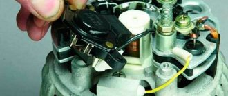
It doesn't matter what type of generator set is used in the car. In any case, it has a regulator in its design. The automatic voltage regulation system allows you to maintain a certain parameter value, regardless of the frequency at which the generator rotor rotates. The figure shows the generator voltage regulator relay, its diagram and appearance.
By analyzing the physics by which a generator set operates, it can be concluded that the output voltage increases as the rotor speed becomes higher. It can also be concluded that voltage regulation is carried out by reducing the current supplied to the rotor winding as the rotation speed increases.
Functionality check
The operating condition of the device can be determined by inspecting the brushes, the length of which must be at least 5 mm. And diagnosing the state of the regulator is carried out by using a constant voltage source on which the initial parameter can be changed. For these purposes, it is enough to have a battery, a couple of AA batteries and a regular 12-volt incandescent lamp or voltmeter.
First you need to connect the “+” from the power supply to the corresponding connector of the relay regulator, and the “-” to the common plate of the device. Next, a lamp or voltmeter is connected to the brushes, which are supplied with a voltage of 12 volts at this time. It is important to understand that when more than 15 Volts are supplied to the regulator, there will be no voltage between the brushes. This is what indicates the working condition of the device. The unit will be diagnosed as faulty in cases where the control lamp does not light up or lights up at any voltage value.
What is a generator
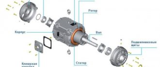
Any car generator consists of several parts:
1. A rotor with an excitation winding, around which an electromagnetic field is created during operation.
2. A stator with three windings connected in a star configuration (alternating voltage is removed from them in the range from 12 to 30 Volts).
3. In addition, the design contains a three-phase rectifier consisting of six semiconductor diodes. It is worth noting that the VAZ 2107 generator voltage relay-regulator (injector or carburetor in the injection system) is the same.
But the generator will not be able to operate without a voltage regulation device. The reason for this is the voltage change over a very wide range. Therefore, it is necessary to use an automatic control system. It consists of a comparison device, control, executive, master and special sensor. The main element is the regulatory body. It can be either electrical or mechanical.
The principle of operation of the voltage regulator
To increase operational reliability, regulators are made according to simplified circuits. Includes several devices: signal comparison, control, master and special sensors.
The finished circuit consists of two main elements:
- Regulator. A device that allows you to adjust and control voltage. It is manufactured in two versions – analog (mechanical) and digital (electronic).
- Graphite brushes that connect to semiconductor elements. Designed to communicate voltage to the rotor of a car generator.
Graphite brushes transmit voltage to the car's generator rotor
Modern devices have a microprocessor base.
Generator operation
When the rotor begins to rotate, some voltage appears at the generator output. And it is supplied to the excitation winding through a control element. It is also worth noting that the generator set output is connected directly to the battery. Therefore, voltage is constantly present on the excitation winding. When the rotor speed increases, the voltage at the generator set output begins to change. A voltage regulator relay from a Valeo generator or any other manufacturer is connected to the generator output.
In this case, the sensor detects the change, sends a signal to a comparing device, which analyzes it, comparing it with a given parameter. Next, the signal goes to the control device, from which it is supplied to the actuator. The regulatory body is able to reduce the value of the current that flows to the rotor winding. As a result, the voltage at the generator set output is reduced. In a similar way, the mentioned parameter is increased in the event of a decrease in rotor speed.
General concepts
It is important to understand what structural parts a car generator consists of.
The rotor creates an electromagnetic field on its field winding.
The stator, which removes alternating voltage in the range from 12-30 Volts, has three windings that are connected according to a star circuit.
Three-phase rectifier, which consists of six diode semiconductors.
Since changes in the voltage level in the generator can occur over a fairly wide range, its normal operation is primarily associated with an automatic adjustment device. It should be noted, for example, that the relay regulator on VAZ 2107 cars, regardless of the technical design of the fuel injection system (injector or carburetor), has the same design. It consists of the following devices: comparison, control, master and executive, as well as a special sensor. The main element of this design is the control element, which can be mechanical or electrical.
When the rotor rotates in a car's generator set, an electrical voltage appears at its output, the level of which on the field winding is controlled by a control element. In addition, the generator is directly connected to the battery, which is why voltage is constantly supplied to the field winding. When the rotor rotation speed changes, the voltage at the generator output also varies, which is regulated by a relay regulator connected to it.
Increasing and decreasing the voltage level at the output of the vehicle's generator set is carried out as follows. First, the sensor detects its change and sends a corresponding signal to the comparing device, which in turn compares it with the set level. Then this signal is sent to the control device, where it is converted and supplied to the actuator. And the regulating device is responsible for changing the current supplied to the rotor winding, as a result of which the voltage at the generator output decreases or increases.
Two-level regulators
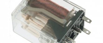
A two-level automatic control system consists of a generator, a rectifier element, and a battery. It is based on an electric magnet, its winding is connected to the sensor. The driving devices in these types of mechanisms are very simple. These are ordinary springs. A small lever is used as a comparison device. It is mobile and makes switching. The actuator is the contact group. The control element is a constant resistance. Such a generator voltage regulator relay, the diagram of which is given in the article, is very often used in technology, although it is morally outdated.
Operation of a two-level regulator
When the generator operates, a voltage appears at the output, which is supplied to the winding of the electromagnetic relay. In this case, a magnetic field arises, with its help the lever arm is attracted. The latter is acted upon by a spring, which is used as a comparing device. If the voltage becomes higher than expected, the contacts of the electromagnetic relay open. In this case, a constant resistance is included in the circuit. Less current is supplied to the field winding. The voltage regulator relay for the VAZ 21099 generator and other domestic and imported cars operates on a similar principle. If the voltage at the output decreases, then the contacts are closed, and the current strength changes upward.
- Currently 2.60/5
Rating 2.6 /5 (122 votes)
The voltage regulator maintains the on-board network voltage within specified limits in all operating modes when changing the generator rotor speed, electrical load, and ambient temperature. In addition, it can perform additional functions - protect the elements of the generator set from emergency conditions and overload, automatically include an excitation winding circuit or an alarm system for the emergency operation of the generator set into the on-board network.
All voltage regulators operate on the same principle. The generator voltage is determined by three factors - the rotor speed, the current supplied by the generator to the load, and the amount of magnetic flux created by the field winding current. The higher the rotor speed and the lower the load on the generator, the higher the generator voltage. Increasing the current in the excitation winding increases the magnetic flux and with it the generator voltage, decreasing the excitation current reduces the voltage.
All voltage regulators, domestic and foreign, stabilize the voltage by changing the excitation current. If the voltage increases or decreases, the regulator accordingly reduces or increases the excitation current and brings the voltage within the desired limits.
The block diagram of the voltage regulator is shown in Fig. 1.
Regulator 1 contains a measuring element 5, a comparison element 3 and a regulating
element 4. The measuring element perceives the voltage of generator 2 Ud and converts it into a signal Umeas., which in the comparison element is compared with the reference value Uet.
If the value of Umeas. differs from the reference value Uet, a signal Uo appears at the output of the measuring element, which activates the control element, which changes the current in the field winding so that the generator voltage returns to the specified limits.
Thus, the voltage regulator must be supplied with generator voltage or voltage from another location on the on-board network where its stabilization is necessary, for example, from a battery, and the generator excitation winding must also be connected. If the functions of the regulator are expanded, then the number of its connections in the circuit increases.
The sensitive element of electronic voltage regulators is the input voltage divider. From the input divider, the voltage is supplied to the comparison element, where the role of the reference value is usually played by the stabilization voltage of the zener diode. The zener diode does not pass current through itself at a voltage below the stabilization voltage and breaks through, i.e. begins to pass current through itself if the voltage across it exceeds the stabilization voltage. The voltage on the zener diode remains practically unchanged.
The current through the zener diode turns on an electronic relay, which switches the excitation circuit in such a way that the current in the excitation winding changes in the desired direction. In vibration and contact-transistor regulators, the sensitive element is presented in the form of a winding of an electromagnetic relay, the voltage to which, however, can also be supplied through an input divider, and the reference value is the tension force of the spring, which counteracts the attractive force of the electromagnet.
Switching in the field winding circuit is carried out by relay contacts or, in a contact-transistor regulator, by a semiconductor circuit controlled by these contacts.
A feature of automotive voltage regulators is that they carry out discrete voltage regulation by turning on and off the excitation winding in the power circuit (in transistor regulators) or in series with the winding of an additional resistor (in vibration and contact-transistor regulators), while the relative duration of switching on the winding changes or an additional resistor.
Since vibration and contact-transistor regulators are of only historical interest, and electronic transistor regulators are currently used in domestic and foreign generator sets, it is convenient to consider the principle of operation of a voltage regulator using the example of a simple circuit close to the domestic voltage regulator YA112A1 and the EE14V3 regulator from BOSCH ( Fig. 2).
Regulator 2 in the diagram works in conjunction with generator 1, which has an additional
field winding rectifier. To understand the operation of the circuit, we should remember that, as shown above, the zener diode does not pass current through itself at voltages below the stabilization voltage. When the voltage reaches this value, the zener diode breaks through and current begins to flow through it.
Transistors pass current between the collector and emitter, i.e. open if current flows in the base-emitter circuit, and do not allow this current to pass through, i.e. closed if the base current is interrupted.
Voltage is supplied to the zener diode VD1 from the output of generator D through a voltage divider across resistors R1, R2. While the generator voltage is low, and at the zener diode it is lower than the stabilization voltage, the zener diode is closed, no current flows through it, and, consequently, in the base circuit of transistor VT1, transistor VT1 is closed. In this case, the current through resistor R6 from pin D enters the base circuit of transistor VT2, it opens, and current begins to flow through its emitter-collector junction in the base of transistor VT3, which also opens. In this case, the excitation winding of the generator is connected to the power circuit through the emitter-collector junction VT3.
The connection of transistors VT2, VT3, in which their collector terminals are combined, and the base circuit of one transistor is powered from the emitter of the other, is called a Darlington circuit. With this connection, both transistors can be considered as one composite transistor with a high gain. Typically, such a transistor is made on a single silicon crystal.
If the generator voltage increases, for example, due to an increase in the rotation speed of its rotor, then the voltage at the zener diode VD1 also increases. When this voltage reaches the value of the stabilization voltage, the zener diode VD1 breaks through, the current through it begins to flow into the base circuit of the transistor VT1, which opens and, with its emitter-collector transition, short-circuits the base output of the composite transistor VT2, VTZ to ground. The composite transistor closes, breaking the power supply circuit of the field winding. The excitation current drops, the generator voltage decreases, the zener diode VD2 and transistor VT1 close, the composite transistor VT2, VTZ opens, the excitation winding is reconnected to the power circuit, the generator voltage increases, etc., the process repeats.
Thus, the generator voltage is adjusted by the regulator discretely by changing the relative time of switching on the excitation winding of the power circuit. In this case, the current in the excitation winding changes as shown in Fig. 3.
If the generator rotation speed has increased or its load has decreased, the winding turn-on time decreases; if the rotation speed decreases or the load increases, it increases.
In the regulator circuit shown in Fig. 2 there are elements characteristic of the circuits of all voltage regulators used on cars. Diode VD2, when closing the composite transistor VT2, VT3, prevents dangerous voltage surges arising from an open circuit in the excitation winding with significant inductance. In this case, the field winding current can be closed through this diode, and dangerous voltage surges do not occur. Therefore, diode VD2 is called a quenching diode.
Resistance R3 is the hard feedback resistance. When the composite transistor VT2, VT3 is opened, it turns out to be connected in parallel to the resistance R2 of the voltage divider. In this case, the voltage on the zener diode VD2 decreases sharply, which speeds up the switching of the regulator circuit and increases the frequency of this switching. This has a beneficial effect on the voltage quality of the generator set.
Capacitor C1 is a kind of filter that protects the regulator from the influence of voltage pulses at its input. In general, capacitors in the regulator circuit either prevent this circuit from entering an oscillatory mode and the possibility of extraneous high-frequency interference influencing the operation of the regulator, or they speed up the switching of transistors. In the latter case, the capacitor, charging at one moment in time, is discharged onto the base circuit of the transistor at another moment, accelerating the switching of the transistor with an inrush of discharge current and, therefore, reducing power losses in it and its heating.
From Fig. Figure 2 clearly shows the role of the lamp for monitoring the operating condition of the HL generator set. When the internal combustion engine is not running, closing the contacts of the ignition switch SA allows current from the battery GA to flow through this lamp into the excitation winding of the generator. This ensures the initial excitation of the generator. At the same time, the lamp lights up, signaling that there is no break in the excitation winding circuit.
After starting the engine, almost the same voltage appears at the generator terminals D and “+” and the lamp goes out. If the generator set does not develop voltage while the car engine is running, the HL lamp continues to light in this mode, which is a signal that the generator set has failed or the drive belt has broken.
The introduction of resistor R into the generator set helps to expand the diagnostic capabilities of the HL lamp. With this resistor present, if the field winding circuit opens while the car engine is running, the HL lamp will light up.
For its reliable operation, the battery requires that as the temperature of the electrolyte decreases, the voltage supplied to the battery from the generator set increases slightly, and as the temperature rises, it decreases.
To automate the process of changing the level of the maintained voltage, a sensor is used, placed in the battery electrolyte and connected to the voltage regulator circuit. In the simplest case, thermal compensation in the regulator is selected in such a way that, depending on the temperature of the cooling air entering the generator, the generator set voltage changes within specified limits.
In the considered voltage regulator circuit, as in all regulators of a similar type, the switching frequency in the field winding circuit changes as the operating mode of the generator changes. The lower limit of this frequency is 25-50 Hz. However, there is another type of electronic regulator circuits in which the switching frequency is strictly specified. Regulators of this type are equipped with a pulse-width modulator (PWM), which provides the specified switching frequency.
The use of PWM reduces the influence on the operation of the regulator of external influences, for example, the level of ripple of the rectified voltage, etc.
Currently, more and more foreign companies are switching to the production of generator sets without an additional rectifier. To automatically prevent the battery from discharging when the car engine is not running, a generator phase is inserted into this type of regulator.
Regulators, as a rule, are equipped with PWM, which, for example, when the engine is not running, switches the output transistor to an oscillatory mode, in which the current in the field winding is small and amounts to fractions of an ampere.
After starting the engine, the signal from the generator phase output switches the regulator circuit to normal operation. In this case, the regulator circuit also controls the lamp for monitoring the operating condition of the generator set.
Related items
- Voltage ranges of domestically produced automotive generator sets
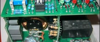
Electronic regulator
Two-level mechanical voltage regulators have a big drawback - excessive wear of the elements. For this reason, instead of an electromagnetic relay, semiconductor elements operating in key mode began to be used. The operating principle is similar, only the mechanical elements are replaced by electronic ones. The sensing element is made on a voltage divider, which consists of constant resistors. A zener diode is used as a driving device.
The modern relay-voltage regulator of the VAZ 21099 generator is a more advanced device, reliable and durable. The executive part of the control device operates on transistors. As the voltage at the generator output changes, the electronic switch closes or opens the circuit, and additional resistance is connected if necessary. It is worth noting that two-level regulators are imperfect devices. Instead, it is better to use more modern developments.
What types of devices are common?
The simplest design is considered to be a two-level regulator. It consists of a generator, rectifier and battery. The winding of the electric magnet underlying the control device is connected in this case to the sensor. An ordinary spring is used here as a setting device, and a small lever plays the role of a comparing device (switching). The contact group works as an actuator. Constant resistance is a control element. Despite the outdated design of this relay-regulator, this design is still quite common.
The operation of a two-level regulator occurs as follows. The voltage that appears at the output of the generator is supplied to the relay winding. The resulting electromagnetic field attracts the arm of the lever, which is acted upon by the spring of the comparison device. When a voltage exceeds the specified parameters, the relay contacts open and a direct current enters the electrical circuit, the level of which is much lower. Accordingly, when the voltage decreases, the relay contacts close, causing the current to begin to increase.
Since the above two-level regulators are characterized by excessive wear of mechanical elements, modern voltage regulators began to use semiconductors acting as switches instead of an electromagnetic relay of this type. In this case, the very principle of operation of the relay regulators has not changed, however, the replacement of mechanical parts with radio-electronic ones is accompanied by the fact that the sensitivity of the voltage divider, made on constant resistors, has increased significantly. In addition, a zener diode is used as a master device.
Modern generator voltage regulators, used, for example, in domestic cars, are quite reliable and durable devices. In them, the executive part operates on semiconductor transistors. In addition, at the output of the generator after the electronic switch, which acts as a switch, if necessary, additional resistance can be connected.
It should be noted that the operating efficiency of three-level voltage regulation designs is noticeably improved. Despite their general fundamental similarity with mechanical two-level relay regulators, there are still differences. In them, information about the voltage level at the output of the generator is processed through a divider to a special circuit. Any car can be equipped with such regulators. In this case, it is only important to understand its structure and connection diagram.
In three-level voltage relay regulators of generators, its current indicator is compared with extreme (min and max) values. In this case, when the voltage level deviates from the specified parameters, a mismatch signal is generated, which affects the regulation of the current strength on the rotor field winding. In addition, the circuit of such a regulator implies the presence of several additional resistances located after the electronic key.
You should know that modern voltage regulation systems on expensive cars use more advanced multi-level devices that contain three or more additional resistances in their circuits. In addition, they can use tracking control systems. And in some car models, instead of additional resistances, the principle of increasing the frequency of key operation is used. Recent developments in multi-level control systems are based on frequency modulation. In them, additional resistances control the logical elements of the structure.
Three-level regulation system
The quality of regulation of such structures is much higher than that of those previously discussed. Previously, mechanical designs were used, but today non-contact devices are more common. All elements used in this system are the same as those discussed above. But the operating principle is slightly different. First, voltage is applied through a divider to a special circuit in which information is processed. It is possible to install such a generator voltage regulator relay (Ford Sierra can also be equipped with similar equipment) on any car if you know the device and connection diagram.
Here the actual value is compared with the minimum and maximum. If the voltage deviates from the value that is set, then a certain signal appears. It is called a mismatch signal. It is used to regulate the current flowing to the excitation winding. The difference from a two-level system is that there are several additional resistances.
Modern voltage regulation systems
If the voltage regulator relay for the generator of a Chinese scooter is two-level, then more advanced devices are used on expensive cars. Multilevel control systems can contain 3, 4, 5 or more additional resistances. There are also tracking automatic control systems. In some designs, you can refuse to use additional resistances.
Instead, the frequency of operation of the electronic key increases. It is simply impossible to use circuits with electromagnetic relays in servo control systems. One of the latest developments is a multi-level control system that uses frequency modulation. In such designs, additional resistances are required, which are used to control logic elements.
How to remove the relay regulator
Removing the generator voltage regulator relay (“Lanos” or domestic “nine” is not important) is quite simple. It is worth noting that when replacing the voltage regulator, you only need one tool - a flat-head or Phillips screwdriver. There is no need to remove the generator or the belt and its drive. Most of the devices are located on the back cover of the generator, and are combined into a single unit with a brush mechanism. The most common breakdowns occur in several cases.
Firstly, when completely erasing the graphite brushes. Secondly, in case of breakdown of a semiconductor element. How to check the regulator will be discussed below. When removing, you will need to disconnect the battery. Disconnect the wire that connects the voltage regulator to the generator output. By unscrewing both mounting bolts, you can pull out the device body. But the voltage regulator relay for the VAZ 2101 generator has an outdated design - it is mounted in the engine compartment, separately from the brush assembly.
Removing the voltage regulator
Operating principle of a synchronous generator
In order to remove the regulator from the back cover of the car generator, you need a screwdriver (phillips or flat-head). The generator itself and the belt do not need to be removed.
The structure can only be removed after disconnecting the battery. Next, you need to disconnect the wire from the car generator by unscrewing the mounting bolts.
The main causes of autogenerator malfunctions:
- erasing carbon brushes;
- breakdown of insulation of semiconductor elements.
Device check
The relay-regulator of the voltage of the VAZ 2106 generator, “kopecks”, and foreign cars is checked equally. As soon as you remove it, look at the brushes - they should be more than 5 millimeters long. If this parameter is different, the device must be replaced. To carry out diagnostics, you will need a constant voltage source. It would be desirable to be able to change the output characteristic. You can use a battery and a couple of AA batteries as a power source. You also need a lamp, it must run on 12 Volts. You can use a voltmeter instead. Connect the plus from the power supply to the voltage regulator connector.
Accordingly, connect the negative contact to the common plate of the device. Connect a light bulb or voltmeter to the brushes. In this state, voltage should be present between the brushes if 12-13 Volts are supplied to the input. But if you supply more than 15 Volts to the input, there should be no voltage between the brushes. This is a sign that the device is working properly. And it doesn’t matter at all whether the voltage regulator relay of the VAZ 2107 generator or another car is diagnosed. If the control lamp lights up at any voltage value or does not light up at all, it means that there is a malfunction of the unit.
Diagnostics of an automobile relay-regulator
First, you need to decide whether checking the relay is necessary at all. First of all, pay attention to incorrect charging of the battery:
- Overcharging is observed . The electrolyte begins to boil away, and the acid solution may fall on body parts;
- Undercharging is observed . The battery charge is constantly low, as a result of which the engine may not start, and the optics may remain incandescent.
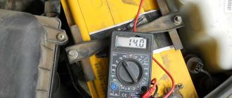
If you observe any of the above, you need to get a tester and start checking the relay regulator. In short, any voltage deviation from the maximum (14.5, in rare cars as much as 14.8 Volts) or minimum (12.8 Volts) at the corresponding speeds indicates the need to replace the relay regulator. Before diagnosing, it is worth measuring the voltage at the terminals of the car battery - normally it is 12.8 Volts.
If the vehicle uses a built-in relay, you need to do the following:
- Remove the brush assembly and, if necessary, select new brushes. Brushes less than 5 millimeters are considered short;
- Take the power source. A power supply or charger that allows you to regulate the voltage to at least 16 Volts . Connect the negative wire of the source to the corresponding terminal of the regulator;
- The “positive” wire of the power source is connected to the corresponding terminal of the relay regulator;
- Connect a 10-watt test lamp to the brushes. If it is not available, an LED will do;
- Apply power from the source to the relay, gradually increasing the voltage. As soon as it exceeds 14.5 or 14.8 Volts (exceptional case), the lamp/LED should go out.
If the relay regulator does not pass the test (the control device does not go out), it is definitely worth changing. If you ignore the problem, the battery will be overcharged on a constant basis, which will eventually lead to its failure. In the case of a built-in relay, checking will become even easier:
- Connect the tester probes to the relay terminals;
- Set the multimeter to 20 Volts ;
- Start the engine and check the voltage indicator - it should be minimal (about 12.8 Volts);
- Increase engine speed. Voltage readings should increase smoothly;
- When the engine is at 3500 rpm , monitor changes in voltage readings. They must fall into the range of 14-14.5 Volts. In some cars the maximum is 14.8 volts.
If you observed serious deviations or, on the contrary, constant voltage regardless of the speed, the relay regulator is clearly faulty. We strongly recommend that even after these checks, you check the regulator terminals once again - oxides and deposits can interfere with correct diagnostics of the device. After cleaning, the diagnosis should be repeated.
conclusions
In the electrical system of a car, the voltage regulator relay of the Bosch generator (as, indeed, of any other company) plays a very important role. Monitor its condition as often as possible and check for damage and defects. Cases of failure of such a device are not uncommon. In this case, in the best case, the battery will be discharged. And in the worst case, the supply voltage in the on-board network may increase. This will lead to the failure of most electricity consumers. In addition, the generator itself may fail. And its repair will cost a tidy sum, and considering that the battery will fail very quickly, the costs will be astronomical. It is also worth noting that the Bosch generator voltage regulator relay is one of the leaders in sales. It has high reliability and durability, and its characteristics are as stable as possible.
Replacing the generator regulator relay
Relay replacement is necessary in the following cases:
- Wear of the brushes, in which contact with the relay-regulator disappears and the generator does not work.
- A breakdown in the device circuit, which causes an increase in voltage in the system.
- Damage to the fasteners or housing, which can lead to a short circuit.
The process of replacing a device is considered using the Lada-Kalina generator as an example. Replacing the relay regulator is associated with dismantling the generator, and is carried out in the following order:
- Removing the minus terminal from the generator.
- Dismantling the generator.
3. Unsnap the plastic clips on the generator cover and remove it.
4. Disconnect the diode bridge connector.
5. Unscrewing the nut and dismantling the contact group bushing.
6. Unscrewing a pair of screws holding the relay regulator.
As you know, in any vehicle the generator is one of the main components, the failure of which will not allow the engine to start. Such a device consists of many components, but one of the most basic is a three-level regulator. What is this voltage device, what is its purpose, what types are there, how to diagnose - read below.