The presence of various electronic assistants in the car allows the driver not to worry about adjusting many systems and mechanisms. Some processes would be completely impossible to control without a partner if automatic devices that perform this function had not been developed and implemented in the electronic circuit of the vehicle. For example, in the absence of a generator voltage relay-regulator, it would not be possible to stably and safely extract electrical power from the generator to charge the battery.
Types of generator voltage relay regulators
Having understood what types of voltage relays can be installed on a car generator, it will be possible to correctly perform diagnostic and repair work. The following types of devices can be used on modern cars:
- Combined.
- Separate.
Combined elements are devices that are integrated into the brush assembly directly in the generator housing. Individual elements can be installed on the car body anywhere in the engine compartment. Relay regulators of this design are connected to the generator and battery via electrical wires.
Separate relay regulators are practically not used in modern cars. This is due to the fact that combined products do not require the allocation of a separate space and the connection of additional conductors. In addition, such parts are often combined in one housing with a brush assembly, which allows the operation of the device to be optimized as much as possible.
Two-level regulators
A two-level automatic control system consists of a generator, a rectifier element, and a battery. It is based on an electric magnet, its winding is connected to the sensor. The driving devices in these types of mechanisms are very simple. These are ordinary springs. A small lever is used as a comparison device. It is mobile and makes switching. The actuator is the contact group. The control element is a constant resistance. Such a generator voltage regulator relay, the diagram of which is given in the article, is very often used in technology, although it is morally outdated.
Signs of a faulty voltage regulator
A characteristic sign of a faulty voltage regulator relay is frequent discharge of the battery. This is explained by the fact that the energy storage device does not receive the necessary recharge from the generator while the engine is running. A faulty relay regulator should be suspected even if the battery is not completely discharged. For example, diagnostic signs such as dim headlights at night or an insufficiently powerful signal sound may indicate failure of this device.
The relay regulator may not supply voltage to the battery terminals or turn off on time. Such a breakdown will cause the battery to overcharge, which can lead to overheating of the internal battery plates and boiling off of the electrolyte.
Signs of a malfunctioning relay regulator may also include:
- Constantly lit battery light on the dashboard.
- The starter does not develop enough power to start the engine easily.
- Reduced engine power (can be especially noticeable at high speeds).
Even if there is one sign of failure, you should check the relay regulator for serviceability.
Generator operation
When the rotor begins to rotate, some voltage appears at the generator output. And it is supplied to the excitation winding through a control element. It is also worth noting that the generator set output is connected directly to the battery. Therefore, voltage is constantly present on the excitation winding. When the rotor speed increases, the voltage at the generator set output begins to change. A voltage regulator relay from a Valeo generator or any other manufacturer is connected to the generator output.
In this case, the sensor detects the change, sends a signal to a comparing device, which analyzes it, comparing it with a given parameter. Next, the signal goes to the control device, from which it is supplied to the actuator. The regulatory body is able to reduce the value of the current that flows to the rotor winding. As a result, the voltage at the generator set output is reduced. In a similar way, the mentioned parameter is increased in the event of a decrease in rotor speed.
Reasons for failure of the relay regulator
Having an idea of the main symptoms of a faulty relay-regulator, as well as the reasons for the failure of this part, you can easily “diagnose” the chocolate bar in the generator without even carrying out additional diagnostic operations.
The most likely causes of failure of the relay regulator are:
- Short circuit in the wiring or generator windings.
- Failure of the generator diode bridge.
- Incorrect battery connection (reverse polarity).
- Mechanical damage.
The relay-regulator can also output when wet. As a rule, the device has a waterproof casing, and the elements inside can be filled with a special resin, but if the protection is damaged, moisture penetration will lead to failure of the electronic components of the regulator. An increased load on the device is also possible in the case when water gets on the generator winding while washing a car or when driving a car during heavy rain.
Operation of a two-level regulator
When the generator operates, a voltage appears at the output, which is supplied to the winding of the electromagnetic relay. In this case, a magnetic field arises, with its help the lever arm is attracted. The latter is acted upon by a spring, which is used as a comparing device. If the voltage becomes higher than expected, the contacts of the electromagnetic relay open. In this case, a constant resistance is included in the circuit. Less current is supplied to the field winding. The voltage regulator relay for the VAZ 21099 generator and other domestic and imported cars operates on a similar principle. If the voltage at the output decreases, then the contacts are closed, and the current strength changes upward.
How to check the generator relay regulator on a car
You can check the generator integral without removing the device from the car. The diagnostic procedure can be performed either using special tools or simple methods that require the use of only simple instruments and devices.
How to test a relay for functionality without a tester
Diagnostics of the relay regulator using measuring equipment and additional devices will require significant costs if the necessary devices are not available. The cost of a new relay regulator is relatively low, and replacing the element requires a minimum amount of time. To make sure that problems in the vehicle's electrical system are caused by this device, it is enough to have a known good part on hand to perform a simple diagnostic operation.
It is not necessary to use a new relay regulator for this purpose. It is enough to check a used spare part in advance so that at any time and without the use of additional equipment you can accurately determine the reason for the non-standard operation of the vehicle’s electrical system.
Checking the generator voltage regulator with a multimeter without installation
Even an inexpensive multimeter or pointer tester can be successfully used to diagnose the generator relay-regulator directly on the car. You can check the device without dismantling it in the following sequence:
- Set the multimeter or tester to DC current measurement mode.
- Start the car engine.
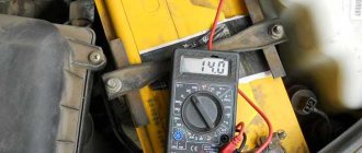
- Measure the voltage at the battery terminals at an engine speed of no more than 1500 rpm (if the part is in good condition, the voltage will be in the range from 13.2 to 14.0 volts).
- Increase the crankshaft speed to 2500 rpm. Measure the voltage at the battery terminals (with the relay-regulator operating normally, the device should show 14.8 volts (an error of 0.2 volts is allowed)).
- Increase engine speed to 3500 rpm and measure the voltage again (should not exceed 14.8 volts if the regulator is working properly).
If, as a result of the measurements, all voltage indicators did not have significant deviations, then the relay-regulator is in good condition. Otherwise, you should purchase and install a new part.
What is a generator
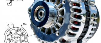
Any car generator consists of several parts:
1. A rotor with an excitation winding, around which an electromagnetic field is created during operation.
2. A stator with three windings connected in a star configuration (alternating voltage is removed from them in the range from 12 to 30 Volts).
3. In addition, the design contains a three-phase rectifier consisting of six semiconductor diodes. It is worth noting that the VAZ 2107 generator voltage relay-regulator (injector or carburetor in the injection system) is the same.
But the generator will not be able to operate without a voltage regulation device. The reason for this is the voltage change over a very wide range. Therefore, it is necessary to use an automatic control system. It consists of a comparison device, control, executive, master and special sensor. The main element is the regulatory body. It can be either electrical or mechanical.
How to check a combined type regulator
The operation of the relay regulator can be established using a simple test circuit, which consists of the following parts:
- DC source with a voltage of 12 V (you must use a device with the ability to adjust the voltage value, as well as with a built-in voltmeter).
- 12 V incandescent light bulbs (use a low-power light source of 3 - 4 W).
- Wires with crocodile fastenings.
Checking the relay regulator is carried out as follows:
- Connect the power source to the relay-regulator, observing the polarity.
- Connect the wires from the light bulb using “crocodiles” with graphite brushes.
- Set the voltage on the electrical device to 12.7 V. The light should be on.
- Increase the voltage to 14.5 V. The light should go out.
If the lighting element does not go out when the voltage reaches 14.5 V, then the regulator is faulty. In some vehicle models, the automatic device may be programmed to turn off when the voltage reaches 14.0 volts. This feature of the device is normal.
If the light bulb does not light up at normal voltage levels or goes out before the electrical device produces a voltage of 14.0 V, then the relay regulator will also need to be replaced.
If there is no source of electricity in the form of a regulated power supply, then you can use a battery and a step-up transformer with regulation.
Checking the voltage regulator of the VAZ 2107 generator
Checking the voltage regulator of the VAZ 2107 generator can be done according to the scheme described above. The principle of cutting off the electric current when a certain voltage level is reached also remains the same. The difference may only lie in the features of connecting the charging relay to the current source and the control lamp. Depending on the year of manufacture of the car, various types of devices may be installed on it. On machines produced before 1996, an old-style relay-regulator was located. Such a device is also diagnosed by connecting the operating voltage to the main terminals and a test light to the brushes. New cars use integral type products (chocolate). Such a device is connected in a similar way. The contacts that go to the generator brushes must be connected to the light bulb, and the other pair to the current source.
How to check a chocolate bar on a KAMAZ generator
The principle of operation of the Kamaz vehicle relay regulator is the same as on other vehicles. When a certain voltage value is exceeded, the regulation device cuts off the power supply to the battery terminals. You can qualitatively check the part using a variable voltage source and a test lamp. A special feature of testing the device is the use of a current source with an adjustable voltage from 20 to 30 volts; accordingly, the light bulb must be of the appropriate type (24 V). It is not recommended to use a high-power lighting element. It is enough to use an incandescent lamp installed in the turn signals.
The work of checking the “chocolate” of the Kamaz generator is carried out as follows:
- Remove the integral voltage regulator from the generator.
- Find 2 contacts of the product that connect to the brushes and connect an electric light bulb to them (the polarity does not matter; it is also recommended to use wires with crocodile clips).
- The “negative” wire of the power supply is connected to the “ground” of the chocolate bar.
- The “plus” of the power supply is connected to the second output of the regulator.
The principle of testing is similar to performing work on 12-volt devices. When a certain voltage level (about 27 volts) is reached, the charging current should be switched off. If this does not happen, the device should be replaced. If the control light does not light up, the chocolate bar should be discarded.
When performing diagnostics using an incandescent lamp, it is necessary to ensure that the electric light source is in good working order, otherwise incorrect results will be obtained from checking the relay regulator of a Kamaz vehicle.
How to check the integral on a generator
To test the integral on a passenger car generator, you can use a battery and an adjustable voltage transformer. You will also need to prepare a multimeter and an incandescent lamp for turn signals. The connection diagram for the generator integral will be as follows:
- An adjustable voltage transformer is connected to the battery.
- The integral is connected to the transformer.
- Wires from the light bulb are connected to the terminals of the integral.
- To monitor the voltage, a multimeter is connected to the circuit between the adjustable transformer and the integral, which should be switched to the constant voltage measurement mode.
The generator integral relay is checked using the following algorithm:
- By increasing the voltage through an adjustable transformer, they control the voltage level at which the light bulb will turn off.
- After turning off the lamp, the voltage is reduced and the moment when the lighting element is turned on is also set.
If the light bulb does not turn off, then the integral should be replaced. In a situation where a working lamp does not light up at all, the regulator must also be replaced.
When carrying out such a check, it is necessary to ensure the reliability of the contacts of the integral terminals with the connected conductors. If the contact elements are dirty, they should be cleaned using a wooden or plastic scraper, and to obtain high-quality contact, use crocodile-type connecting elements.
Improvement of the electronic voltage regulator.
In the collection “To Help the Radio Amateur,” issue 53, the article “Electronic Voltage Regulator” (pp. 81 - 90) describes several electronic voltage regulators for a car. The amplifying-actuating element of all these devices uses a powerful germanium transistor P210A (T3). The choice of this particular transistor was due to the absence of a silicon analogue of the pnp structure.
Nevertheless, it is obvious that a silicon transistor is preferable here, since it ensures more reliable operation of the voltage regulator at elevated temperatures. Therefore, a regulator circuit was developed, similar in principle of operation and characteristics to the device according to the circuit in Fig. 5 in the article mentioned above, but with a powerful silicon transistor of the p-p-p structure.
Read also: Connector for Internet cable
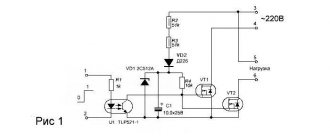
The regulator (see diagram) has some features that it is advisable to briefly discuss. The use of silicon transistor KT808A (V9; transistor KT803A can also be used) required the inclusion of an additional transistor V8 (P303A; it can be replaced with P302 - P304, P306, P306A with a static current transfer coefficient of at least 15), which also increases sensitivity devices.
Rice. Voltage regulator circuit
In the measuring element in the voltage divider, instead of a resistor, a diode circuit V1, V2 is used, which provides temperature compensation for the zener diode V3. With this change, the temperature instability of the voltage regulator as a whole is reduced to almost zero.
Minor changes in the base circuit of transistor V5 compared to the original version did not fundamentally change the operation of the generator maximum current limiter, but improved the smoothness and increased the accuracy of setting the limit threshold.
Once assembled, the simplest voltage regulator on one transistor was intended for a specific power supply and a specific consumer; of course, there was no need to connect it anywhere else, but as always, there comes a moment when we stop doing the right thing. The consequence of this is troubles and thoughts about how to live and be further and the decision to restore what was created earlier or continue to create.
How to check a separate voltage regulator on a generator
Voltage regulators installed separately from the generator can be installed on older car models. Failure of such parts can also lead to overcharging or missing charge of the battery, so you should check it at the first suspicion of non-standard operation of this element.
Checking the generator voltage regulator relay type 591 3702 01
The principle of checking the regulator type 591 3702 01 is identical to other devices of this type. You will also need to connect the products to a DC source and, by changing the output voltage values on the power supply, set the moment when the control lamp turns off.
A design feature of the type 591 3702 01 regulator is the output part, which has contacts designated “67” and “15”. Contact “67” is the “minus” of the system, so the corresponding wire from the power source, which is connected in series with the incandescent lamp, should be connected to it. Also, the negative contact should be connected to the “ground” of the regulator (metal mount). Contact “15” is the plus of the device, so the positive conductor should be connected to it.
The device is checked according to the standard procedure. First, the operating voltage is applied at which the light bulb should light. When the maximum possible voltage (14.5 V) is exceeded, the electric current in the circuit disappears.
More precisely, the relay-regulator type 591 3702 01 can be checked on a special diagnostic stand. This installation has a generator, battery and voltmeter. The regulator is connected on the stand in the same way as when installed on a car. After starting the stand, adjusting the rotation of the generator ensures that the voltage exceeds the cut-off threshold (14.5 V). The device shutdown is recorded by a voltmeter.
If the relay regulator does not turn off the voltage supply when a critical level is reached or there is no electric current immediately after starting the generator, then you will need to replace the relay regulator type 591 3702 01.
How to check a three-level voltage regulator relay
Instead of a standard relay-regulator, a three-level relay can be installed on cars. Such devices are more advanced and reliable. The difference between three-level relays and “chocolate bars” is the ability to arbitrarily set the cutoff voltage using the built-in regulator.
Testing a three-level relay is carried out according to the standard scheme, when an adjustable source of electric current and a test lamp are connected to the relay. When performing the test, only the previously set cut-off voltage limits should be taken into account. That is, if, using manual adjustment, the shutdown moment was set at 14.7 V, then at this voltage the disappearance of the electric current will be the norm.
Generator check
If an overcharge of the battery can be caused by a malfunction of the relay-regulator, then if the battery is undercharged, the part may be completely serviceable. Various generator breakdowns can cause a permanent or temporary lack of electrical current to fully restore the battery. If the car has a separate relay-regulator, then this part can be easily excluded from the electrical circuit and thus ensure that the generator is working properly. The diagnostic operation is performed with the engine running as follows:
- Disconnect the wires from the relay regulator (pins 15 and 67).
- Instead of a relay regulator, a 12 V incandescent lamp should be connected to the circuit.
- Disconnect the positive cable from the battery while the engine is running.
If the engine continues to run when the positive terminal is disconnected, then the car’s generator is working. Otherwise, you should check this part and all additional elements involved in the transmission of electrical energy.
Voltage regulation in diesel generators
Generators in modern diesel generator sets are made using a non-contact circuit. This means that the transfer of electrical energy between the stationary stator and the rotating rotor is carried out only through electromagnetic fields, without the use of rotating rings and brushes. Non-contact synchronous machines do not require periodic maintenance of the brush-commutator unit and have a high degree of reliability. The generators work in conjunction with an analog or digital voltage regulator. Voltage regulation is carried out by changing the magnetic flux of the generator, for which the voltage regulator changes the excitation current of the generator.
In the given expression: - voltage at the generator terminals; – its load current; — internal resistance of the generator; — electromotive force; – magnetic flux of the generator; n – rotor speed; c is a constructive constant.
The magnetic flux of the generator depends nonlinearly on the excitation current () and the load current of the generator.
From the above relationships it is clear that the voltage at the machine terminals will depend on the load current, rotational speed and excitation current. The rotation speed of the synchronous generator is kept constant to ensure a constant current frequency.
Figure 1.19 shows a diagram of a contactless synchronous generator operating in conjunction with a transistor voltage regulator. The non-contact generator consists of three electrical machines: sub-exciter, exciter and main generator.
| Fig.1.19 |
The subexciter is of magnetoelectric type, i.e. it is excited by permanent magnets that are located on the rotor.
The anchor winding is three-phase and is placed on the generator stator. The subexciter powers the voltage regulator and control system, which makes their operation independent of external power sources. The exciter and main generator have electromagnetic excitation. The exciter field winding (EFW) is located on the stator and it is connected to the voltage regulator. The armature winding is multiphase and located on the rotor. The armature winding, through rectifiers located on the rotor, supplies the excitation winding of the main generator (MG) with direct current. The armature winding of the main generator is three-phase, located on the stator and connected in a star with the neutral brought out. This design of the generator also makes it possible to reduce the power of the voltage regulator, since the exciter in this case acts as an amplifier of the excitation current of the main generator. In the presented simplified diagram, the voltage regulator includes a voltage measurement unit (BIN), a control pulse width modulator (PWM), and an output transistor VT operating in the key mode.
The voltage measurement unit consists of a step-down three-phase transformer, a three-phase rectifier, and a measuring element using two zener diodes VD1, VD2 and resistors R2, R3. Voltage regulators for three-phase generators regulate the average value of three phase or line voltages; in this case, the average line voltage is regulated. Voltage averaging is performed by a three-phase rectifier. The measuring element has the characteristic shown in Fig. 1.20a, where: UIO is the output voltage (voltage between points a and b) of the measuring element; UN is the rated voltage of the generator. The magnitude of the generator voltage supplied to the measuring element can be regulated by resistor R1. Using this resistor, you can set the generator voltage value that the regulator will support.
| Fig.1.20 |
The pulse width modulator generates control signals (UУ) for the transistor; the shape of the control signals is shown in Fig. 1.20b.
Here: IB is the current of the exciter excitation winding; tО – time of the transistor open state; tЗ – time of the closed state of the transistor; IVSR is the average value of the current through the OVV winding. When the transistor is open, the supply voltage (UP) is applied to the excitation winding and the current in it increases; when it is closed, it decreases, i.e. the current fluctuates around the average value. If you increase the duration tO, while maintaining the pulse repetition period (shown by the dotted line), then the average current value will increase ( ). The open time of the transistor is characterized by the duty cycle of the control pulses (Kγ).
.
Thus, by changing the duty cycle, it is possible to regulate the excitation current of the generator, and, consequently, its voltage.
,
where RВ is the resistance of the excitation winding.
The voltage stabilization process proceeds as follows. If a load is connected to the generator, its voltage will decrease, this will lead to a decrease in the voltage at the output of the measuring element, as a result of which the LMA will increase the Kγ coefficient and the exciter excitation current will increase. The voltage in the armature winding of the exciter will increase, which will lead to an increase in the excitation current of the main generator and its voltage will increase.
The regulator also has flexible and rigid negative feedbacks to ensure the stability of the control system. In parallel operation, the reactive current of the generator is controlled through the voltage regulator, for which the regulator can be equipped with a reactive current sensor.
Control questions
1. How is the current frequency stabilized in diesel generators?
2. What is the purpose of a synchronizer in diesel generators?
3. Explain the reasons for the change in generator voltage when its load changes.
4. How to change the voltage value of a diesel generator?
5. How will the Kγ coefficient change as the generator voltage increases?
Recommendations for increasing the service life of the regulator
If the faulty relay regulator is not detected in time, the battery may need to be replaced. Constant boiling of the electrolyte or complete discharge has a very negative impact on the performance of the battery. To minimize the negative impact of such situations, you should properly care for the elements of the vehicle’s electrical system to prevent the regulator from failing. The most effective preventive measures aimed at maintaining this part in working condition are:
- Regular cleaning of the generator. The presence of internal short circuits in the stator and rotor windings can be the main reason for the failure of the regulator, so regular maintenance of this part will significantly extend the life of the “chocolate” or a device installed separately in the engine compartment.
- Scheduled and unscheduled tightening of the generator belt. If there is even slight slippage of the belt, a significant decrease in the performance of the generator can be observed, therefore, at the slightest suspicion of weakening of this element, adjustment work should be performed immediately.
- Cleaning contact wires from oxidation. A high-quality supply of electric current from the generator to consumers will avoid power surges and failure of many devices, including the relay regulator.
Regular monitoring of the voltage at the battery terminals under different engine operating modes will allow you to timely determine the incorrect operation of the regulator relay. Detecting a breakdown at an early stage of problem development will allow you to avoid serious consequences.
Device check
The relay-regulator of the voltage of the VAZ 2106 generator, “kopecks”, and foreign cars is checked equally. As soon as you remove it, look at the brushes - they should be more than 5 millimeters long. If this parameter is different, the device must be replaced. To carry out diagnostics, you will need a constant voltage source. It would be desirable to be able to change the output characteristic. You can use a battery and a couple of AA batteries as a power source. You also need a lamp, it must run on 12 Volts. You can use a voltmeter instead. Connect the plus from the power supply to the voltage regulator connector.
Accordingly, connect the negative contact to the common plate of the device. Connect a light bulb or voltmeter to the brushes. In this state, voltage should be present between the brushes if 12-13 Volts are supplied to the input. But if you supply more than 15 Volts to the input, there should be no voltage between the brushes. This is a sign that the device is working properly. And it doesn’t matter at all whether the voltage regulator relay of the VAZ 2107 generator or another car is diagnosed. If the control lamp lights up at any voltage value or does not light up at all, it means that there is a malfunction of the unit.
Repair or replacement of the voltage regulator - what to choose
When various parts fail, the driver often makes a difficult decision: repair the part and install a new one. With a car relay regulator, such a dilemma arises only when using a car that was produced several decades ago. It is almost impossible to purchase new spare parts for rare car models, and disassembled parts may be of dubious quality. When an integrated device (chocolate bar) is used to adjust the battery charge level, such a device cannot be repaired. The parts installed in relay regulators of this type can be restored, but this work will require certain knowledge and skills, as well as significant time investment.
Replacing the generator relay regulator
If the relay regulator can no longer be used for its intended purpose, then a new part should be installed. The combined element changes in the following sequence:
- Disconnect the negative terminal of the battery.
- Disconnect the fasteners.
- Remove the brush assembly cover.
- Disconnect the diode bridge.
- Unscrew the contact group nuts.
- Unscrew the threaded elements holding the regulator.
- Remove the part.
Installation of a new regulator is carried out in the reverse order of removal. When performing this operation, the element contacts must be connected correctly.
Depending on the generator model, the process of replacing the relay regulator may differ slightly. The main thing is to perform dismantling, if possible, without damaging other elements of the generator set.
Replacing an individual element is much easier. For this purpose, it is enough to disconnect the main 2 contacts from the device, remove the product from the car body and install a new part in its place. Then correctly connect the previously removed wires and check the operation of the device. To do this, just start the engine and measure the voltage at the battery terminals at different speeds.
Voltage regulator repair
You can try to disassemble and repair old models of relay regulators that are installed separately. It should immediately be noted that such an activity has little promise, but if you ring the internal elements with a multimeter and find the burnt part, you can completely restore the functionality of the regulator.
Repairing the regulator relay can take too much time, so it is much easier and more correct to purchase a new product or remove the device from another car in which this part is in known good condition.
To find out whether a car relay-regulator is working correctly or not, it is enough to carry out simple diagnostics using a multimeter or a test lamp. If the device being tested does not show signs of life, then it is enough to change the part to restore the functionality of the electrical system. Repairing a “chocolate” or “tablet” is practically impossible, but other types of regulators can also be restored with great difficulty. Therefore, if the battery is not charging or too much voltage is supplied to the battery, you need to purchase a new product from a specialized store.
How to remove the relay regulator
Removing the generator voltage regulator relay (“Lanos” or domestic “nine” is not important) is quite simple. It is worth noting that when replacing the voltage regulator, you only need one tool - a flat-head or Phillips screwdriver. There is no need to remove the generator or the belt and its drive. Most of the devices are located on the back cover of the generator, and are combined into a single unit with a brush mechanism. The most common breakdowns occur in several cases.
Firstly, when completely erasing the graphite brushes. Secondly, in case of breakdown of a semiconductor element. How to check the regulator will be discussed below. When removing, you will need to disconnect the battery. Disconnect the wire that connects the voltage regulator to the generator output. By unscrewing both mounting bolts, you can pull out the device body. But the voltage regulator relay for the VAZ 2101 generator has an outdated design - it is mounted in the engine compartment, separately from the brush assembly.