Today, many people use dimmer. The dimmer can fail quite often. Most often this happens when protective devices are not installed in the house. The devices are considered sensitive to voltage surges. If increased loads occur, then the device may simply break.
In this article you will find the main reasons that may affect the performance of the device. You will also find detailed information on how to perform high-quality dimmer repairs yourself.
Causes of dimmer failures
Most often, the cause of failure may be exceeding the maximum permissible load or a short circuit in the load. Excess of load occurs when, for example, lovers of good lighting screw too powerful lamps into chandeliers. Or several lamps are connected through a dimmer, which in total consume too much power.
By the way, when choosing a dimmer, you should select the power with a margin of 30...50%. How to increase the power of a dimmer will be discussed and shown in this article.
A short circuit is possible not only due to faulty wiring. It happens that when light bulbs burn out, a short circuit (short circuit) occurs in them, the nature of which we will not delve into.
In addition, at the moment the incandescent lamp is turned on, a current flows through it, several times higher than the working one. Read more in the article about the resistance of an incandescent lamp.
Illuminated model
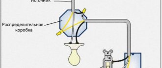
There are light switches equipped with backlighting. The essence of this device is that an LED with a resistor or a miniature neon indicator lamp is mounted parallel to the main contacts. The diagram of this embodiment is shown below:
When the lighting is turned off, current flows through the lighting lamp(s) and the LED with a current-limiting resistor. Its value is too small to light a lamp, but is sufficient to light an LED. Thus, the diode light helps to find the light switch in a dark room. When we turn on the lamp, the contacts bypass the LED, it is de-energized and goes out.
In addition to ease of use, this scheme makes it possible to check the condition of the switch contacts. After all, the backlight circuit is an analogue of the same test lamp with which you can check a regular switch. For example, if you pressed a key, the light did not turn on, and the LED did not stop lighting, then the contacts did not close.
Malfunctions of dimmers on a triac
As a result of a short circuit and overload, a triac usually fails . This is the main malfunction; it occurs in 90% of breakdown cases.
The triac is the main element. Its distinctive features are three terminals and a radiator screwed to the body. The most common models are BT137, BT138, BT139.
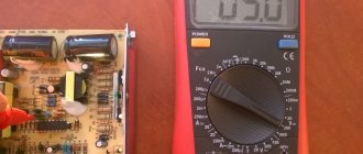
A faulty triac can be detected with a multimeter. If you test the resistance between terminals A1 and A2 (or T1 and T2, the first and second terminals) in ohmmeter mode, it will be from zero to several ohms. Conclusion - the triac has definitely burned out.
There is another case - the triac rings normally (infinite resistance), but the dimmer, however, does not work (the lamp does not light in all positions of the regulator). Only checking will help here, i.e. inclusion in a real circuit.
Replacing the triac will be discussed in detail below.
In addition to a faulty triac, there are other dimmer faults:
- The power tracks of the printed circuit board burn out. This is a consequence of the main malfunction. The paths will have to be restored with jumpers.
- The mechanical integrity of the regulator (potentiometer or variable resistor) is damaged. From frequent and intensive use, no explanation is needed here.
- In dimmers that have a fuse, you must first check it before repairing. Often the manufacturer provides a spare one, which is stored in the same dimmer as the worker. Rational decision. If it had been in a separate bag, it would have definitely gotten lost.
- Mechanical failure of contacts and soldering of the printed circuit board. First of all, soldering the contacts where the wires are screwed. It also happens that electronic elements are simply poorly soldered by the manufacturer.
- Malfunctions of individual elements. First of all - dinistor, then resistors and capacitors.
Illuminated model
There are light switches equipped with backlighting. The essence of this device is that an LED with a resistor or a miniature neon indicator lamp is mounted parallel to the main contacts. The diagram of this embodiment is shown below:
When the lighting is turned off, current flows through the lighting lamp(s) and the LED with a current-limiting resistor. Its value is too small to light a lamp, but is sufficient to light an LED. Thus, the diode light helps to find the light switch in a dark room. When we turn on the lamp, the contacts bypass the LED, it is de-energized and goes out.
In addition to ease of use, this scheme makes it possible to check the condition of the switch contacts. After all, the backlight circuit is an analogue of the same test lamp with which you can check a regular switch. For example, if you pressed a key, the light did not turn on, and the LED did not stop lighting, then the contacts did not close.
Dimmer circuit
Before repairing, let's look at the dimmer circuit. Compared to the previous article about the dimmer, I slightly reworked and clarified the diagram. In the last article I left the scheme the same. But in the new one, I did not change the numbering of parts, so as not to cause confusion.
Dimmer circuit for incandescent lamps using a triac
The dimmer that we will repair has exactly this circuit.
Dimmer repair procedure
Now I will give an example of how to replace a triac with your own hands, using a drill, soldering iron, and an ordinary toothpick.
The triac can be replaced by unscrewing the radiator and removing the triac from the board. But the radiator is now being riveted. The rivet is much more technologically advanced and cheaper in mass production.
Therefore, we pick up a drill with a drill with a diameter of 3.5...5.5 mm.
1 Drill out the radiator rivet
The arrow shows the direction of the drill.
2 Remove the radiator from the triac
The radiator has been removed, now you need to carefully remove the bad triac, causing minimal damage to the board. Recommended soldering iron power is 25 or 40 W.
3 Unsolder the triac from the board. The triac outputs are designated T1, T2, Gate.
Plus, a soldering iron requires experience and dexterity.
A soldering iron with a power of 60 Watts or more can easily damage the board.
Next, we prepare a place for the new triac, using a wooden toothpick for this:
4 Prepare the holes for the new triac
5 Board is ready
6 Place for a new triac
The sites are stuck together, but that doesn’t matter yet.
And here are the triac friends, next to the DB3 dinistor:
7 New triacs and DB3 dinistor
The triacs (BT139, BT138, BT137) in the photo are all for a voltage of 800 Volts, the maximum operating current is 16, 12, and 8 Amps, respectively.
The datasheet can be downloaded at the end of the article.
Now we insert a new part into these through holes:
8 Triac is sealed
9 Trimming the legs (conclusions))
The jumper was unsuccessful, it was necessary to use thinner wires...
We carefully check the soldering to ensure there is no short circuit between the contact pads.
Next, we mount the radiator. At home, it is cheaper and more technologically advanced to use a M3 screw, washer and nut.
10 All that remains is to screw on the radiator
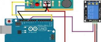
Now all that remains is to check the operation in a real connection circuit. Let me remind you that the dimmer is turned on in the same way as a regular switch:
Turning on the light bulb through the brightness control.
For the test circuit, I use a light bulb of any power in the socket, a wire with a plug, and a Vago 222 terminal block.
How to disassemble a switch
Nowadays, in many houses, high-quality electrics are initially installed, or during repairs they try to replace all elements of the electrical network, including switches.
But a situation may arise when you come home, flip the switch, and the light does not come on. If the light bulb works in another place and there is electricity in the apartment, then the problem is most likely in the switch, and it will have to be disassembled.
This must be done by first turning off the power and checking it on a lamp or lamp.
Now there are several types of switches, each of which has its own design and features. The following types of switches are distinguished:
- Simple one- and two-key switches. The most common type of switches.
- Pass-through switches can turn on lights from several places. In appearance they look like regular push-button switches.
- Dimmers are switches that allow you to adjust the brightness of lighting from twilight to bright light. They come with microcontrollers or mechanical ones.
- Impulse switches are essentially just buttons, like doorbells. They are connected to a pulse relay.
- Touch switches - there are different types: acoustic (triggered by a sharp sound, for example, clapping your hands), touch dimmers, with a remote control, radio switches, etc.
Since key switches are the most common, we will consider disassembling them.
How to turn off the power supply
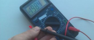
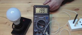
Before any electrical work, including disassembling the switch, it is necessary to turn off the voltage. As a rule, electrical wiring in our apartments is divided into three groups: sockets, lighting and output for an electric stove (if there is one). To disassemble the switch, it is necessary to de-energize the lighting group by turning off the corresponding circuit breaker on the distribution panel. But many people have a question: what kind of automatic machine is responsible for lighting?
The photo shows an image of a modern panel, where the ratings of the machines are shown in close-up (16 Amps on the right and 5 Amps on the left). The lighting wiring always carries less current than the group of sockets, therefore the rating of the machine for this group will be lower - this is what you need to focus on.
After turning off the machine, you must make sure that the voltage is turned off - to do this, turn on the lighting and if it is not there, then everything is done correctly and you can start disassembling the electrical switch
How to disassemble a switch
I can find both single-key switches and two- and three-key switches. The most common are two-key ones, and the sequence of work will be shown using their example.
First you need to remove the keys from the switch. This is done quite quickly and easily without special tools. You need to press the key against the wall with your thumb, and with your other fingers take it by the protruding edge and pull it towards you. Many people are afraid of breaking the key because it is held quite tightly, in which case you can use a flat-head screwdriver or a knife and slightly pry the key. Still, it’s better to use your hands, and after a while everything will work out. Next, use the same principle to remove the second key.
After this, you need to remove the switch frame itself. It can be pressed against the mechanism by the black bet located in the middle. This is a latch type fastening, so you need to use a small flat screwdriver to pry this insert open as shown in the photo. After this, the switch mechanism itself will become accessible.
In order to remove the switch from the wall, you need to loosen the mounting tabs that hold it. To do this, loosen the corresponding screws (shown in the photo) and after that the mechanism should freely come out of the wall. Sometimes the switch may be secured with screws on the sides of the mounting box, in which case they must be unscrewed.
Then the switch is removed from the box and the voltage on the connected wires is checked using a special indicator screwdriver. If everything is done correctly, then there should be no voltage. After this, unscrew the fastenings of all wires and disconnect them from the switch. The removed switch must be inspected for melted contacts, and if this is the problem, then the switch cannot be repaired and must be replaced. If there are no such problems, then the switch is inspected for other damage and all contacts are checked, especially in the places where the wires are attached.
Two more dimmers. Appearance of printed circuit boards.
Bonus – more photos:
11 The track on the board is burned out
12 Dimmer board
13 Dimmer board, view of the triac
Resistors are color coded. Did you learn as I recommended?
14 markings on the radiator
Broken dimmer, triac needs to be replaced
Broken dimmer, triac needs to be replaced
Similarities between dimmers and lamp protection units
I described in detail the lamp protection blocks that smoothly turn on the brightness of the lamps in my articles about the design and connection and diagram of such blocks.
The difference between dimmers and BZ is only in the control method. In protection blocks, the triac is controlled by a controller according to the program. And the program can be anything, up to a wave-like change in brightness. Any analog or digital signal can be controlled. There would be demand.
If you are interested in what I write about, subscribe to receive new articles and join the group on VK!