Best answers
A:
Apply power to pins 11 and 4, connect headphones to pins 9 and 13 via 10uF, for example, and touch the 5,6 and 3,2 pins - if the ms is working, the background in the headphones will be 50Hz. So I tested this MS about 20 years ago - the easiest way, probably.
El Kunkin:
replacement only—————solder the socket and plug in the mikrukha————well, or if you have an oscillation generator, then it’s easier
Georgy Glurjidze:
Only by connection
Techie:
only by connection
Andrey Nechaev:
You can throw off the tester to check the op-amp. You can assemble a headphone amplifier on a breadboard. R1 R2 amplifier gain.
How to check the audio amplifier in a radio
To figure out and understand how to check whether the sound amplifier in the radio is working or not, you need to apply an algorithm similar to checking a car amplifier. That is:
- check the presence of power and short circuit in the power supply system;
- carefully inspect the circuit board for the presence of clearly failed elements and radio components;
- check the tight fit of the radiator to the transistors and microcircuits of the output stages.
There are many ways and techniques for ringing a sound amplifier, but not all specialists want to reveal the secret of finding a fault.
Operational Amplifier Tester
Author: Victorovich Published 03/14/2013 Created using KotoEd.
Three options
Checking microcircuits is a rather complex process, which often turns out to be impossible. The reason lies in the fact that the microcircuit contains a large number of different radioelements. However, even in this situation there are several ways to check:
- visual inspection. By carefully examining each element of the microcircuit, you can detect a defect (cracks in the case, burnt contacts, etc.);
- checking power with a multimeter. Sometimes the problem lies in a short circuit on the part of the power supply; replacing it can help correct the situation;
- performance check. Most microcircuits have not one, but several outputs, so a malfunction of at least one of the elements leads to failure of the entire microcircuit.
The easiest to check are the KR142 series microcircuits. They have only three pins, so when any voltage level is applied to the input, a multimeter checks its level at the output and draws a conclusion about the state of the microcircuit.
The next most difficult tests are the K155, K176, etc. series microcircuits. To check, you need to use a block and a power source with a specific voltage level selected for the microcircuit. Just as in the case of KR142 series microcircuits, we apply a signal to the input and monitor its output level using a multimeter.
Checking the functionality of the PWM controller.
The PWM controller is considered the “heart” of power supplies, but first you need to check other components of the power supply by following the standard sequence of actions for repairing a power supply unit (PSU):
1) When the source is turned off, carefully inspect the source (pay special attention to the condition of all electrolytic capacitors - they should not be swollen).
2) Check the serviceability of the fuse and the elements of the power supply input filter.
3) Check for a short circuit or open circuit in the rectifier bridge diodes (this operation, like many others, can be performed without desoldering the diodes from the board). In other cases, you must be sure that the circuit being tested is not shunted by the windings of the transformer or resistor (in suspicious cases, the circuit element must be unsoldered and checked separately).
4) Check the serviceability of the output circuits: electrolytic capacitors of low-frequency filters, rectifier diodes and diode assemblies.
5) Check the power transistors of the high-frequency converter and the transistors of the control cascade. Be sure to check the return diodes connected in parallel to the collector-emitter electrodes of the power transistors.
These actions give a positive result in detecting only the consequences of the inoperability of the entire unit, but the cause of the malfunction in most cases is much deeper. For example, a malfunction of power transistors can be a consequence of: a malfunction of the protection and control circuit circuits, a malfunction of the feedback circuit, a malfunction of the PWM converter, a failure of the damping RC circuits, or an interturn breakdown in the power transformer. Therefore, if you can find a faulty element, then it is advisable to go through all the stages of checks listed above (since the fuse itself never burns out, and a broken diode in the output rectifier also causes the “death” of the power transistors of the high-frequency converter).
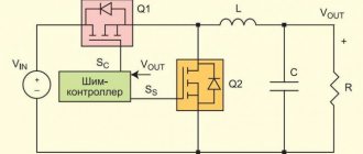
For a long time, the TL494 chip was used as a PWM controller (the “heart” of power supplies), and then its analogues (MB3759, KA7500B ... KA3511, SG6105, etc.). The functionality of such a microcircuit, for example, TL494 (Fig. 1), can be checked without turning on the power supply. In this case, the microcircuit must be powered from an external source with a voltage of +9V..+20V. Voltage is supplied to pin 12 relative to pin. 7 - preferably through a low-power rectifier diode. All measurements must also be carried out relative to the pin. 7. When applying power to the microcircuit, we control the voltage at the pin. 5. It should be +5V (±5%) and be stable when the supply voltage to the pin changes. 12 Within +9V..+20V. Otherwise, the internal voltage stabilizer of the microcircuit is faulty. Next, use an oscilloscope to look at the voltage at the pin. 5. It should be sawtooth-shaped with an amplitude of 3.2 V (Fig. 2). If the signal is absent or of a different form, then check the integrity of the capacitor and resistor connected to the pin. 5 and pin. 6, respectively. If these elements are in good condition, the microcircuit must be replaced. After this, we check the presence of control signals at the output of the microcircuit (pin 8 and pin 11). They must correspond to the oscillograms shown in Fig. 2. The absence of these signals also indicates a malfunction of the microcircuit. If the tests are successfully completed, the microcircuit is considered operational.
Rice. 1
Rice. 2
al-tm.ru
Using a special tester
For more complex checks, you need to use a special microcircuit tester, which you can purchase or make yourself. When dialing individual components of the microcircuit, data will be displayed on the display screen, analyzing which you can come to a conclusion about the serviceability or malfunction of the element.
It is worth remembering that in order to fully test the microcircuit, you need to completely simulate its normal operating mode, that is, ensure the supply of voltage at the required level. To do this, the test should be carried out on a special test board.
Often, it turns out to be impossible to test a microcircuit without soldering the elements, and each of them must be called separately. How to ring individual elements of the microcircuit after desoldering will be discussed below.
Example of protection implementation
Figure 4 shows a fragment of a computer power supply circuit diagram, which clearly shows a typical varistor connection (highlighted in red).
Figure 4. Varistor in the ATX power supply
Judging by the figure, the circuit uses the TVR 10471K element, we use it as an example of decoding the markings:
- the first three letters indicate the type, in our case this is the TVR series;
- the next two digits indicate the diameter of the case in millimeters, respectively, our part has a diameter of 10 mm;
- Then there are three numbers that indicate the effective voltage for this element. It is deciphered as follows: XXY = XX*10y, in our case it is 47*101, that is, 470 volts;
- the last letter indicates the accuracy class, “K” corresponds to 10%.
You can also find simpler markings, for example, K275, in this case K is the accuracy class (10%), the next three digits indicate the magnitude of the effective voltage, that is, 275 volts.
Main settings
If you look closely at the electrical characteristics of the K157UD2, you will notice that in terms of performance, this microcircuit is not for use in audio devices. Thus, the highest rate of voltage rise at its output is 0.5 V/µs, which is comparable to an output signal of up to approximately 10 V/8 kHz. In real life it will be even lower. But for its time it was also a good indicator.
Maximum values
Here are the main limit values of the parameters:
- maximum power supply (UPit) up to ±18 V;
- output voltage (Uout max.) up to ± 13 V (at Upit = ± 15 V);
- zero offset voltage (U cm) up to ± 13 V;
- current consumption (I sweat) up to 7 mA;
- short circuit current (I short circuit) up to 45 mA;
- cutoff frequency (f srz) from 1 MHz;
- gain (KуU): no less than 50000 (at f =0...50 Hz) and 800 (at f =20 kHz);
- output slew rate (VUout) of at least 0.5 V/µs.
Exceeding the maximum permissible values may lead to device failure.
The typical value of the noise voltage used at the input of this op-amp (in the frequency range from 20 to 20,000 Hz) is no more than 1.6 μV.
Analogs
It is believed that the imported analogue of the K157UD2 is LM301. But, firstly, this microcircuit has 8 pins, instead of 14. Therefore, to replace it you will have to look for two such devices. Secondly, they will be very difficult to find in our stores.
What else can replace K157UD2? A good alternative for this device is the new LME49XXX series microcircuits. More precisely, in most cases the following are suitable: LME49720, LME49860 and LM4562. They are very similar in their characteristics to the one under consideration, they have good linearity and bandwidth (up to 90 Hz), not only at a gain of 1, but also significantly higher (1000 and higher).
Typical noise voltage in the frequency range from 20 to 20,000 Hz is within 0.4 μV. Domestic analogues: KR1434UD1A and updated modification K157U D3. The problem is that now they are difficult to find on Russian shelves and they are more expensive.
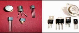
Transistors (field-effect and bipolar)
We switch the multimeter to the “testing” mode, connect the red probe to the base of the transistor, and touch the collector terminal with the black one. The display should show the breakdown voltage value.
A similar level will be shown when checking the circuit between the base and emitter. To do this, connect the red probe to the base, and apply the black probe to the emitter.
The next step is to check the same transistor terminals in reverse connection. We connect the black probe to the base, and with the red probe we touch the emitter and collector in turn. If the display shows one (infinite resistance), then the transistor is working. This is how field-effect transistors are tested.
Bipolar transistors are checked using a similar method, only the red and black probes are swapped. Accordingly, the values on the multimeter will also show the opposite.
Check on the motherboard
So, when the board's power is turned on, the protection is triggered. First of all, you need to check the resistance of the stabilizer arms with a multimeter.
A radio components tester can also be used for these purposes. If one of them shows a short circuit, that is, the measured resistance is less than 1 Ohm, then one of the key field-effect transistors is broken.
Identifying a broken transistor if the stabilizer is single-phase is not difficult - a faulty device, when checked with a multimeter, shows a short circuit. If the stabilizer circuit is multiphase, and this is how the processor is powered, parallel connection of transistors takes place. In this case, you can determine the damaged device in two ways:
- dismantle the transistor and check the resistance between its terminals with a multimeter for breakdown;
- Without soldering the transistors, measure and compare the resistance between the gate and source in each phase of the converter. The damaged area is identified by a lower resistance value.
The second method does not work in all cases. If the broken element could not be determined, you will still have to unsolder the transistor.
Next, the damaged transistor is replaced, and all radio elements that were soldered off during the diagnostic process are replaced. After this, you can try to start the board.
The first startup after repair is best done by removing the processor and setting the appropriate jumpers . If the first run was successful, you can carry out a load test, monitoring the temperature of the mosfets.
Malfunctions of the PWM controller can manifest themselves in the same way as a breakdown of the mosfets, that is, the power supply goes into protection. At the same time, checking the transistors themselves for breakdown does not give any results.
In addition, the consequence of a malfunction of the PWM controller may be the absence of output voltage or its discrepancy with the nominal value. To check the PWM controller, you should first study its datasheet. The presence of high-frequency voltage in pulse mode, in the absence of an oscilloscope, can be determined using a quartz tester on a microcontroller.
Capacitors, resistors and diodes
The serviceability of the capacitor is checked by connecting the probes of a multimeter to its terminals. Within a second, the resistance will increase from a few ohms to infinity. If you swap the probes, the effect will repeat.
To ensure that the resistor is working properly, it is enough to measure its resistance. If it is different from zero and less than infinity, then the resistor is working.
Checking diodes from a microcircuit is quite simple. By measuring the resistance between the anode and cathode in direct and reverse sequence (switching the multimeter probes), we make sure that in one case one is at the level of several tens to hundreds of Ohms, and in the other it tends to infinity (one in the “dialing” mode on the display ).
Inductance and thyristors
Checking the coil for a break is carried out by measuring its resistance with a multimeter. The element is considered serviceable if the resistance is less than infinity. It should be noted that not all multimeters are capable of testing inductance.
The thyristor is checked as follows. We apply the red probe to the anode, and the black one to the cathode. The multimeter window should display infinite resistance.
After this, we connect the control electrode to the anode, observing the drop in resistance on the multimeter display to hundreds of ohms. We disconnect the control electrode from the anode - the resistance of the thyristor should not change. This is how a fully functional thyristor behaves.
Zener diodes, cables/connectors
To test the zener diode you will need a power supply, a resistor and a multimeter. We connect the resistor to the anode of the zener diode, through the power supply we apply voltage to the resistor and the cathode of the zener diode, gradually raising it.
On the display of a multimeter connected to the zener diode terminals, we can observe a smooth increase in the voltage level. At a certain point, the voltage stops increasing, regardless of whether we increase it with the power supply. Such a zener diode is considered serviceable.
To check the loops, you need to ring the contacts with a multimeter. Each contact on one side must call a contact on the other side in the “dialing” mode. If the same contact rings with several at once, there is a short circuit in the cable/connector. If it doesn’t ring with any of them, it’s a break.
Sometimes faulty elements can be determined visually. To do this, you will have to carefully examine the microcircuit under a magnifying glass. The presence of cracks, darkening, or broken contacts may indicate a breakdown.
Not everyone knows how to test a microcircuit for functionality with a multimeter. Even if you have a device, it is not always possible to do this. Sometimes it is easy to identify the cause of a malfunction, but sometimes it takes a lot of time and in the end there are no results. You have to replace the microcircuit.
Check on the motherboard
So, when the board's power is turned on, the protection is triggered. First of all, you need to check the resistance of the stabilizer arms with a multimeter.
A radio components tester can also be used for these purposes. If one of them shows a short circuit, that is, the measured resistance is less than 1 Ohm, then one of the key field-effect transistors is broken.
Identifying a broken transistor if the stabilizer is single-phase is not difficult - a faulty device, when checked with a multimeter, shows a short circuit. If the stabilizer circuit is multiphase, and this is how the processor is powered, parallel connection of transistors takes place. In this case, you can determine the damaged device in two ways:
- dismantle the transistor and check the resistance between its terminals with a multimeter for breakdown;
- Without soldering the transistors, measure and compare the resistance between the gate and source in each phase of the converter. The damaged area is identified by a lower resistance value.
The second method does not work in all cases. If the broken element could not be determined, you will still have to unsolder the transistor.
Next, the damaged transistor is replaced, and all radio elements that were soldered off during the diagnostic process are replaced. After this, you can try to start the board.
The first startup after repair is best done by removing the processor and setting the appropriate jumpers . If the first run was successful, you can carry out a load test, monitoring the temperature of the mosfets.
Malfunctions of the PWM controller can manifest themselves in the same way as a breakdown of the mosfets, that is, the power supply goes into protection. At the same time, checking the transistors themselves for breakdown does not give any results.
In addition, the consequence of a malfunction of the PWM controller may be the absence of output voltage or its discrepancy with the nominal value. To check the PWM controller, you should first study its datasheet. The presence of high-frequency voltage in pulse mode, in the absence of an oscilloscope, can be determined using a quartz tester on a microcontroller.