Transistors, along with capacitors and resistors, are one of the main elements on electrical device boards and are almost always present in circuit design. These parts control current from a small impulse, so incorrect selection, any breakdown leads to a significant disruption in the functionality of the devices, and often because of this they burn out. We will describe ways to check a transistor, and this will need to be done when analyzing faults in electrical appliances and when selecting spare parts for assemblies.
What is a transistor
Transistors replaced electric lamps and made it possible to reduce the number of relays and switches in devices. These are semiconductor triodes - radio-electronic components made from semiconductors; they have 3 terminals as standard.
Transistors are designed to control current, that is, the main power factor of electrical circuits; it is its shock (not voltage) that poses a danger to humans.
The element is capable of controlling extremely high values in output circuits when applying a weak input signal. Transistors boost, generate, switch, and convert electrical signals; they are the basis of microelectronics and electrical devices.
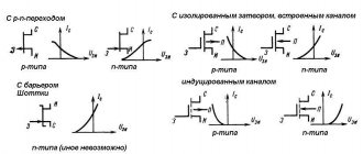
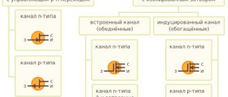
Varieties based on operating principle:
- bipolar transistor made of 2 types of conductors, the basis of its operation is the interaction of adjacent pn sections on the crystal. They consist of an emitter/collector/base (hereinafter, we will abbreviate these terms): the latter receives a weak current, causing a modification of the resistance (hereinafter referred to as “resistance”) in the line consisting of the first 2 elements. Thus, the flowing quantity changes, the side of its unidirectionality (npn or pnp) is determined by the characteristics of the transitions (sections) in accordance with the polarity of the connection (reverse, forward). Control is carried out by modulating the current on the base/emitter segment, the output of the latter is always common for control and output signals;
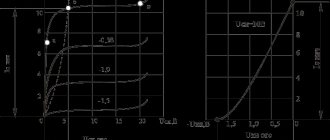
- field. There is only one type of conductor - a narrow channel subject to the electric field of a separate gate passage. Control is based on modulating the number of volts between it and the source. And between the latter and the drain an electric current flows (2 working contacts). The value has a strength depending on the signals generated between the gate (control contact) and one of the specified parts. There are products with a pn control section (working contacts are connected to a p- or n-semiconductor) or with separate gates.
Field workers have polarity options; low voltage is required for control; due to their efficiency, they are installed in radio circuits with low-power power supplies. Bipolar variants are activated by currents. In analog assemblies, the latter (BT, BJT) prevail, in digital (processors, computers) - the former. There are also hybrids - IGBTs, used in power circuits.
Tsokolevka
Medium and high power bipolar transistors have basically the same pinout, from left to right - emitter, collector, base. It is better to check for low power transistors. This is important because when determining performance, we will need this information.
Appearance of a medium power bipolar transistor and its pinout
That is, if you need to determine whether a bipolar transistor is working or not, you need to look for its pinout. If you want to make sure or don’t know where the “face” is, then look for information in a reference book or type the “name” of your semiconductor device on your computer and add the word “datasheet”. This is a transliteration from English Datasheet, which translates as “technical data”. For this request, you will receive a list of characteristics of the device and its pinout.
Read also: Canopy over gates and wicket photo
Checking bipolar types
Below is a diagram for checking npn, pnp transistors with a tester, after which we will describe the procedure point by point.
The bipolar transistor is equipped with pn lines - conventionally, these are diodes, or rather, 2 of them located oppositely, the point of their intersection is the “base”.
One conditional diode is designed with base/collector contacts, the other with base/emitter contacts. For analysis, just look at the contrast. (directly and back) of the indicated areas: if there are no problems there, then the part is without flaws.
Do-it-yourself testing without soldering a bipolar pnp, npn transistor involves testing 3 combinations of legs:
pnp option
Structures (types) are shown by the arrow emitting. section: pnp/npn (to/from the base). Let's start by checking the first option. We open the PNP part by applying negative voltage to the base. On the multimeter, we set the selector to measure Ohms to o; it is also possible to set it to “continuity”.
The vein “−” (black) is on the base leg. Plus (red) - alternately to collect., emitter. If the areas are not damaged, they will display about 500–1200 Ohms.
Next we will describe how to ring the reverse resistance: “+” - to the base, “−” - to the call. and emits. High resistance should be displayed. on both pn sites. We now have “1”, that is, for the frame set to “2000” the value exceeds 2000. This means that there are 2 transitions without breaks, the product is in good working order.
Similarly, as described, you can test the transistor for serviceability without removing it from the circuit. Less commonly, there are assemblies where substantial shunting is applied to the transitions, for example, with resistors. Then, if too low resistance is displayed, the part will need to be desoldered.
npn structure
Npn elements are checked in the same way, only the “+” probe goes to the base from the tester.
Symptoms of a problem
If the resistance (direct and reverse) of one of the sections (pn) tends to infinity, that is, at o and above on the display “1”, which means that this section has a break, the transistor is unusable. If “0” means the product is also flawed, the area is broken. Direct cont. there should be 500–1200 ohms.
How to test a transistor without desoldering it?
Soldering any part from an electrical appliance is a very responsible matter, in which the slightest mistake can completely damage any electrical appliance.
So how can you test a transistor without desoldering it from the circuit?
- First you need to ensure its integrity.
- Then check its generation.
- Next, you should pay attention to L2, which is located near the opening of the red probes.
- The glow of lamp L2 indicates its performance.
If lamp L2 does not light, then this is a sure sign that the device is broken. In this case, it is not recommended to repair it yourself, since there is a high probability that you will damage other parts during the repair.
We advise you to contact a competent specialist with this problem who can repair the transistor.
Where is the base, collector, emitter
We determine the base leg (the mode is the same - “2000 Ohms”): “+” of the tester we touch the left contact, “−” - the rest one by one.
Legs left/middle “1”, left/right - 816 Ohms. So far this is not very informative. Use the “+” probe for the middle contact, “−” for the rest.
The result is similar. The next stage: “+” on the right leg, “−” on the middle and then on the left.
We get “1” each, that is, resistance. is the same in these areas and it goes to infinity. It turns out that we measured the inverse of this value on both pn segments. So the base is the right leg. But the complete procedure for checking serviceability involves finding a call. and emits. direct resistance measurements We touch the base output with a minus, and the rest with a “+”.
The leg on the left is 816 Ohm, this is emitter, the middle leg is 807 Ohm, this is collector, the value there is always lower.
The result is this:
- available type - pnp;
- base on the right, em. - left; coll. - in the middle.
Varieties
In modern electronics, 2 main types of signal amplifiers are used: field and bipolar. Each type is endowed with the ability of electrical conductivity and amplification.
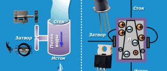
Field-effect transistor
Field-effect transistors are designed to control a signal using an electromagnetic field. This element consists of:
- A gate that serves as a regulator of the incoming voltage.
- A drain from the channel of which charges come out.
- The source through which electrical charges enter.
Such elements contain a semiconductor material, around which there are regions with opposite conductivity. When voltage is applied to the gate of the element, the areas expand, which facilitates the passage of electric current. Due to the incoming voltage to the gate, the conductivity of the element can be adjusted. The space created between the areas is the channel of the transistor. There are 2 types of channels:
- The built-in one opens the way for currents with certain amplitudes. With appropriate polarity and amplitude, it becomes possible to adjust the channel width, and therefore influence the overall conductivity.
- The induced one is a closed channel. It opens only if a certain voltage is applied to the gate.
Thus, field elements are divided into permanently open and closed. They are distinguished by the following parameters:
- Input resistance.
- Amplitude characteristic.
- The polarity applied to the semiconductor.
Both types of transistors can be used on the same board to create signals of the required size.
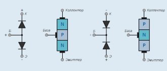
Bipolar
A bipolar transistor operates on the principle of simultaneous passage of electrons of different polarities. To achieve this, their design uses 3 semiconductor regions. Bipolar transistors come in 2 types: PNP and NPN. Elements of type N have a negative charge at the input, type P is positive. Bipolar radio parts consist of:
- Collector for the highest amplitude current.
- Bases for controlling amplitude current.
- Emitter for current output from the collector.
For N-type transistors, current flows from the emitter to the collector. For P types, current flows from the collector through the base to the emitter. You can find out which transistor is in the circuit by looking at the arrow in the designation. Also bipolar elements include lowercase elements. They have a higher threshold for the passage of electrical voltage, since they are under heavy load.
Next, step-by-step instructions will be given on how to test the transistor with a multimeter.
Checking field effect transistors
Continuity, without desoldering, of the field-effect transistor, similar to that for an unmounted copy. Field workers are sensitive to static - before the event it is removed by grounding. It is enough to touch the spare part with one hand and the heating batteries with the other. To check field-effect transistors, their pinout is determined before the procedure.
Markers by which you can determine the conclusions (not always available, especially on domestic products): S - source, D - drain, G - gate. They also look at the technical documentation; the data is available on the Internet.
How to test a field effect transistor:
- We remove the static.
- We set the mode for semiconductors (“dialing”).
- We insert the red “+” wire and the black “–” wire into the corresponding sockets of the multimeter.
- “+” to the source, “−” to the drain. Operating condition: 0.5–0.7 V.
- We change the probes. If the numbers go to infinity, the transistor is working.
- “+” to the gate, “−” to the source, opening occurs. We do not disconnect the last wire, the first one goes to the drain. A working copy will show 0–800 mV. We change the polarity of the wires - the values should not change.
- We close: “−” - to the gate, “+” - to the source.
The serviceability of the field switch is determined by its opening/closing (whether this is observed at all) by applying a low voltage from the tester. The input capacitance in the element is large, and it takes a certain time to discharge. This is important, since first the multimeter opens with a small voltage (item 4), and then measurements must be taken within a short period (items 6, 7).
The procedure for checking a field-effect transistor of type p is the same as for n, only you need to connect the red probe to “−” and the black probe to “+”, that is, change the polarity.
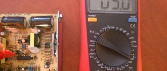
How to test a transistor with a multimeter with a built-in function
Let's start with the fact that there are multimeters with the function of checking the functionality of the transistor and determining the gain. They can be identified by the presence of a characteristic block on the front panel. It has a socket for installing a transistor, a round colored plastic insert with holes for the legs of a semiconductor device. The color of the insert can be any, but usually it stands out.
First of all, move the range switch (large knob) to the appropriate position. The mode can be identified by the inscription - hFE. Before checking the transistor with a multimeter, we determine the NPN or PNP type.
Multimeter with transistor test function
Next, we consider the connectors into which the electrodes must be inserted. They are signed in Latin letters: E - emitter, B - base, C - collector. In accordance with the inscriptions, we place the leads of the semiconductor element into the sockets. After a few moments, the measurement result is displayed on the screen; this is the gain of the transistor. If the device is faulty, there will be no readings, the transistor is faulty.
As you can see, it’s easy to check whether a transistor is working or not with a multimeter with a built-in testing function. But not all electrodes fit into the sockets properly. It is convenient to install transistors with thin leads S9014, S8550, KT3107, KT3102. For large ones, you need to change the shape of the terminals with tweezers or pliers, but you can’t check the transistor on the board that way. In some cases, it is easier to check the transitions of the transistor in the continuity mode and determine its serviceability.
Composite transistors
To test a composite transistor, you need to turn it on. It is convenient to use a pointer tester installed for resistance analysis. (1000 or 2000 Ohm). For the npn type: probe “+” - for the collector, negative - for the emitter. For pnp it's the other way around. The arrow will be indestructible (at the beginning of the “infinity” section), and in the digital multimeter “1”. If you moisten your finger and make a short circuit, touch it to the leg of the base and the commutator, the arrow will move, as the part will open slightly. The serviceability of the transistor is confirmed.
Sziklai pair and cascode circuit
Another name for a compound semiconductor triode is a Darlington pair. In addition to her, there is also a couple of Siklai. This is a similar combination of a dyad of basic elements, which differs in that it includes different types of transistors.
As for the cascode circuit, this is also a variant of a composite transistor, in which one semiconductor triode is connected according to a circuit with an OE, and the other according to a circuit with an OB. Such a device is similar to a simple transistor, which is included in a circuit with an OE, but has better frequency characteristics, high input impedance and a large linear range with less distortion of the transmitted signal.
IGBT test
IGBTs have an insulated gate and are 3-electrode power semiconductor elements. Here, 2 transients are connected in cascade. in 1 structure: field and bipolar (control and power channels).
You can analyze the transistor on the board and soldered using a similar method. The tester is used to analyze semiconductors (“continuity”, diode icon) or resistance. 2000 Ohm. Then the resistance is measured. in the emitter/gate section straight and back. This way we will identify the short circuit, if there is one. Next, the red wire is connected to the emitter, the black wire is briefly touched to the shutter. The latter is charged with negative voltage, the transistor remains closed.
The next point is to confirm functionality. The gate-emitter input section is charged with positive voltage: at the same time, the red conductor is briefly touched to the gate, and the black conductor is briefly touched to the emitter.
Next, we check the transition point between the calls. and emitter: red wire to the first, black to the other. If a slight drop in value of 0.5–1.5 V is displayed and the value lasts for several seconds. stable, then input. The capacity is intact, the transistor is working.
Testing powerful high-voltage transistors has a peculiarity. If the multimeter voltage is not enough to open the IGBT, then 9–15 V sources are used to charge it at the output, for example, a 9 V Krona battery.
Basic types of transistors
There are two main types of transistors - bipolar and field-effect. In the first case, the output current is created with the participation of carriers of both signs (holes and electrons), and in the second case - only one. Testing the transistor with a multimeter will help determine the malfunction of each of them.
Bipolar transistors are essentially semiconductor devices. They are equipped with three pins and two pn junctions. The operating principle of these devices involves the use of positive and negative charges - holes and electrons. Flowing currents are controlled using a specially dedicated control current. These devices are widely used in electronic and radio engineering circuits.
Bipolar transistors consist of three-layer semiconductors of two types - “p-p-p” and “p-p-p”. In addition, the design has two pn junctions. The semiconductor layers are connected to external terminals through non-rectifying semiconductor contacts. The middle layer is considered the base, which is connected to the corresponding pin. Two layers located at the edges are also connected to the outputs - the emitter and collector. In electrical circuits, an arrow is used to indicate the emitter, indicating the direction of current flowing through the transistor.
In different types of transistors, holes and electrons - carriers of electricity - can have their own functions. The most common type is p-p-p due to the best parameters and technical characteristics. The leading role in such devices is played by electrons, which perform the main tasks of ensuring all electrical processes. They are approximately 2-3 times more mobile than holes, and therefore have increased activity. Qualitative improvements in devices also occur due to the collector junction area, which is significantly larger than the emitter junction area.
Each bipolar transistor has two pn junctions. When testing a transistor with a multimeter, this allows you to check the performance of the devices by monitoring the resistance values of the transitions when direct and reverse voltages are connected to them. For normal operation of the p-p-p-device, a positive voltage is applied to the collector, under the influence of which the base junction opens. After the base current occurs, the collector current appears. When a negative voltage occurs in the base, the transistor closes and the current flow stops.
The base junction in pnp devices opens when exposed to negative collector voltage. Positive voltage causes the transistor to turn off. All the necessary collector characteristics at the output can be obtained by smoothly changing the current and voltage values. This allows you to effectively test the bipolar transistor with a tester.
There are electronic devices in which all processes are controlled by the action of an electric field directed perpendicular to the current. These devices are called field-effect or unipolar transistors. The main elements are three contacts - source, drain and gate. The design of the field-effect transistor is complemented by a conductive layer that acts as a channel through which electric current flows.
These devices are represented by modifications of the “p” or “p”-channel type. Channels can be located vertically or horizontally, and their configuration can be volumetric or near-surface. The latter option is also divided into inversion layers containing enriched and depleted ones. The formation of all channels occurs under the influence of an external electric field. Devices with near-surface channels have a metal-dielectric-semiconductor structure, which is why they are called MOS transistors.
Digital transistors
A digital transistor is a special type, there are specifics on how to check it correctly.
The components of digital transistors are resistors. (R1 and 2), their rating is the same (10, 22, 47 kOhm) or mixed, different. Externally, the product has a normal appearance, but when ringing, significant differences arise.
A convenient device for checking transistors is an ampere-voltmeter, you can also take a multimeter. When the direction is direct, when the segment is open, resistance will appear on the tester. approximately comparable to the base resist. R1. When changing the polarity of the probes, the base/emitter point. closed, current flows through resistors connected in series. R1 (10 kOhm) and 2 (22 kOhm), the display will show the sum of their resistances, in our example 32 kOhm.
Base-issue segment. (VD2) is shunted by resistor R2. The resistance there should be approximately 10 times lower than R2, and when the polarity of the AVOmeter is changed, it should be infinitely greater.
Construction and details.
Due to the simplicity of the device, no printed circuit board was developed; all elements are soldered to the pins of switches and connectors. The entire structure can be assembled in a small case; everything will depend on the dimensions of the transformer and switches used.
When testing powerful bipolar transistors at high currents (100mA and 500mA), they must be mounted on a radiator ! If a plate radiator is mounted on one of the walls of the device or the radiator itself is used as a wall of the device, this will make using the device more convenient. A radiator that is always with you! This will significantly speed up the process of testing powerful transistors in TO220, TO126, TOP3, TO247 and similar packages.
The power supply stabilizer chip also needs to be installed on a small radiator. Any diode bridge is suitable for a current of 1A and higher. As a transformer, you can use a suitable small-sized one, with a power of 10 W or more with a secondary winding voltage of 10-14 V.
Optional: the device for testing transistors has sockets for connecting a second multimeter (included in the DC voltage measurement mode to a limit of 2-3V). I spotted this idea on one of the forums. This allows you to measure Ube of the transistor (if necessary, calculate the slope). This function is very convenient when selecting bipolar transistors of the same structure for PARALLEL connection in one arm of the amplifier output stage. If at the same current the voltages Ueb differ by no more than 60 mV, then such transistors can be connected in parallel WITHOUT emitter current equalizing resistors. Now do you understand why Accuphase amplifiers, where up to 16 transistors are connected in parallel in each arm in the output stage, cost so much money?
List of elements used:
Resistors: R3 - 820 Ohm, 0.25 W, R4 - 1k2, 0.25 W, R5 - 510 Ohm, 0.25 W, R6 - 260 Ohm, 0.25 W R7 - 5.1 Ohm, 5 W (more is better), R8 - 26 Ohm, 1 W, R9 - 51 Ohm, 0.5 W, R10 - 1k8, 0.25 W.
Capacitors:
C1 - 100nF, 63V, C2 - 1000uF, 35V, C3 - 470uF, 25V
Switching:
S1 - switch type P2K or biscuit for three positions with two groups of contacts for switching, S2 - switch type P2K, toggle switch or biscuit with one group of contacts for switching, S3 - switch type P2K or biscuit for two positions with four groups of contacts for switching, S4 - momentary button, S5 - power switch
Active elements:
T3 - transistor type KT3102 or any low-power npn type with high gain, D3 - TL431, VR1 - integrated stabilizer 7812 (KR142EN8B), LED1 - green LED, BR1 - diode bridge for a current of 1A.
Miscellaneous:
Tr1 is a transformer with a power of 10W or more, with a secondary winding voltage of 10-14V, F1 is a 100mA...250mA fuse, terminals (suitable available) for connecting measuring instruments and the transistor under test.
Thyristor testing
Let's also consider how to ring thyristors; they are in many ways similar to the parts under consideration. There are 3 pn segments, but the mode does not change after the control signal - this is the difference. The structures run alternately like stripes on a zebra crossing. Thyristor is open until the flow value drops “to the holding current”. Such details allow you to create economical circuits.
The multimeter is set to 2000 ohms. To open the thyristor being tested, the black wire goes to the cathode, the red wire goes to the anode. The part opens with both a “+” and “−” charge. In two cases, resistance must be less than "1". The part is open if the value of the control pulse exceeds the holding frame; if it is less, the key is closed.
Assembling a makeshift sampler
A homemade device (probe) will allow you to instantly determine the serviceability of a transistor of any type. Let us present an elementary effective scheme.
What you will need (3 working components in total):
- the basis is any small downshift. (from pulsed power supplies, ballast for housekeeper light bulbs, small electrical appliances). Our primary has 24 turns with a middle tap; secondary - 15;
- further, 2 elements. The LED is connected to the secondary through a resistor. 100 Ohm, its power is not important, as is the polarity of the first element, since a variable value appears at the output.
There is also a slot for inserting parts to be tested according to the pinout. For bipolar straight-through types (KT 814...818 and so on), the base goes through a resist. to one of the transform contacts, medium output. which (tap) is connected to the “+” power supply. Emit. connect to “−” power supply, collection. - to have a free day off. primary If the conductivity of the part is reversed, then simply change “+” and “−”. Similarly with field workers, the main thing is to maintain the pinout. If light appears after power is applied, then the product is working.
The probe is powered from 3.7–6 V; a lead or lithium-ion battery is suitable.
Bottom line
Any transistor is checked with a multimeter. You need to find out the purpose of its legs (base/col./emitter, drain/source/gate). Next, set the tester to “continuity” or to the 2000 Ohm mark. Then analyze forward and reverse resistance. Based on the result, you can determine the performance of the transistor. You can also analyze the coefficient. amplification: the tester has a special socket and an hFE mark.